EP0809073B1 - Assemblage d'un arbre de transmission - Google Patents
Assemblage d'un arbre de transmission Download PDFInfo
- Publication number
- EP0809073B1 EP0809073B1 EP97107877A EP97107877A EP0809073B1 EP 0809073 B1 EP0809073 B1 EP 0809073B1 EP 97107877 A EP97107877 A EP 97107877A EP 97107877 A EP97107877 A EP 97107877A EP 0809073 B1 EP0809073 B1 EP 0809073B1
- Authority
- EP
- European Patent Office
- Prior art keywords
- drive shaft
- flue gas
- housing
- shaft unit
- guide fins
- Prior art date
- Legal status (The legal status is an assumption and is not a legal conclusion. Google has not performed a legal analysis and makes no representation as to the accuracy of the status listed.)
- Expired - Lifetime
Links
- UGFAIRIUMAVXCW-UHFFFAOYSA-N Carbon monoxide Chemical compound [O+]#[C-] UGFAIRIUMAVXCW-UHFFFAOYSA-N 0.000 claims description 31
- 239000003546 flue gas Substances 0.000 claims description 31
- 239000007789 gas Substances 0.000 claims description 20
- 230000008646 thermal stress Effects 0.000 description 3
- 239000002184 metal Substances 0.000 description 2
- 238000011084 recovery Methods 0.000 description 2
- 239000002918 waste heat Substances 0.000 description 2
- 238000010521 absorption reaction Methods 0.000 description 1
- 230000005540 biological transmission Effects 0.000 description 1
- 239000002131 composite material Substances 0.000 description 1
- 238000010276 construction Methods 0.000 description 1
- 230000008602 contraction Effects 0.000 description 1
- 238000001816 cooling Methods 0.000 description 1
- 230000003111 delayed effect Effects 0.000 description 1
- 238000010438 heat treatment Methods 0.000 description 1
- 238000000034 method Methods 0.000 description 1
- 230000035882 stress Effects 0.000 description 1
Images

Classifications
-
- F—MECHANICAL ENGINEERING; LIGHTING; HEATING; WEAPONS; BLASTING
- F16—ENGINEERING ELEMENTS AND UNITS; GENERAL MEASURES FOR PRODUCING AND MAINTAINING EFFECTIVE FUNCTIONING OF MACHINES OR INSTALLATIONS; THERMAL INSULATION IN GENERAL
- F16K—VALVES; TAPS; COCKS; ACTUATING-FLOATS; DEVICES FOR VENTING OR AERATING
- F16K11/00—Multiple-way valves, e.g. mixing valves; Pipe fittings incorporating such valves
- F16K11/02—Multiple-way valves, e.g. mixing valves; Pipe fittings incorporating such valves with all movable sealing faces moving as one unit
- F16K11/04—Multiple-way valves, e.g. mixing valves; Pipe fittings incorporating such valves with all movable sealing faces moving as one unit comprising only lift valves
- F16K11/052—Multiple-way valves, e.g. mixing valves; Pipe fittings incorporating such valves with all movable sealing faces moving as one unit comprising only lift valves with pivoted closure members, e.g. butterfly valves
-
- F—MECHANICAL ENGINEERING; LIGHTING; HEATING; WEAPONS; BLASTING
- F23—COMBUSTION APPARATUS; COMBUSTION PROCESSES
- F23L—SUPPLYING AIR OR NON-COMBUSTIBLE LIQUIDS OR GASES TO COMBUSTION APPARATUS IN GENERAL ; VALVES OR DAMPERS SPECIALLY ADAPTED FOR CONTROLLING AIR SUPPLY OR DRAUGHT IN COMBUSTION APPARATUS; INDUCING DRAUGHT IN COMBUSTION APPARATUS; TOPS FOR CHIMNEYS OR VENTILATING SHAFTS; TERMINALS FOR FLUES
- F23L11/00—Arrangements of valves or dampers after the fire
Definitions
- the invention relates to a drive shaft unit for a flue gas damper in the flue gas duct of a gas turbine.
- Hot flue gas flows in a gas and steam turbine system from the gas turbine by a heat recovery steam generator, in which Steam is generated for the steam turbine. Can if necessary the gas turbine can also be operated alone, the then hot flue gas is discharged into the atmosphere via a bypass chimney becomes.
- a gas flap is usually arranged in the gas turbine. This flue gas flap is used to close or Opening the cross section of a flue gas inlet duct in the Heat recovery steam generator with simultaneous opening and closing the cross-section of the bypass chimney.
- a flue gas valve is for example from DE-AS 10 49 524 or from the magazine BWK, volume 36 (1984), No. 10, pages 409f., known.
- Such a flue gas damper is usually over a Lever arrangement driven, which in turn via a in Flue gas duct arranged to one outside the flue gas duct arranged actuator connected drive shaft unit is operated.
- the flue gas duct of the gas turbine and all those arranged in it Components must withstand significant thermal loads be designed. Significant thermal loads occur, for example then when within a short time of the combined Gas and steam turbines on pure gas turbine operation is switched and the about 500 to 600 ° C hot flue gas must be removed via the bypass chimney. Because the drive shaft unit for power transmission from the servomotor to the Flue gas damper is provided, it also occur high mechanical Loads on. Therefore, the interpretation of the Drive shaft unit to make particularly high demands.
- the invention is therefore based on the object of a drive shaft unit for a flue gas damper in the flue gas duct specify a gas turbine, which is for particularly high mechanical and thermal loads is designed and thus also in combination with only one servomotor a particularly long one Has lifespan.
- the drive shaft unit a housing enclosing a drive shaft has the recesses for receiving on the shaft circumference distributed guide fins, a first Set of guide fins is firmly connected to the housing, and with a second set of leaders in these assigned recesses in the longitudinal direction of the drive shaft is movable.
- the invention is based on the consideration that both against mechanical as well as against thermal stresses particularly robust drive shaft unit on the one hand a particularly low thermal inertia and on the other hand should have a particularly high torsional strength.
- a Reduction in thermal inertia is due to a reduction the mass of the drive shaft unit. Around to ensure high torsional strength despite the reduced mass, can the drive shaft of one with it in the direction of rotation be surrounded by frictionally connected housing.
- the housing is fixed relative to the drive shaft. Because when the drive shaft unit heats up or cools down the housing heated up earlier than the drive shaft or is cooled, however, arise between the housing and drive shaft thermal stresses due to thermal Expansion processes. This can be compensated for by the sliding arrangement of the second set of guide fins in the recesses assigned to them.
- the advantages achieved with the invention are in particular in that the drive shaft unit with high torsional strength has a particularly low mass. So is they are particularly stable both thermally and mechanically.
- the drive shaft unit with high torsional strength has a particularly low mass. So is they are particularly stable both thermally and mechanically.
- the flue gas duct 1 of the (not shown) gas turbine according to Figure 1 includes a metal compensator as components or duct pieces 2, via a diffuser 4 to a deflection device 6 is connected.
- the deflection device 6 is on the output side with a bypass chimney 8 and with a nozzle 10 for flue gas supply to a not shown Waste heat boiler connected.
- the metal compensator 2, the diffuser 4, the deflection device 6 and the nozzle 10 are on a common foundation 11 arranged.
- a flue gas flap 12 Inside the deflection device 6 is a flue gas flap 12 arranged.
- the flue gas flap 12 is by means of a Drive shaft unit 14 drivable lever arrangement 16 around a pivot axis 18 pivotable.
- the drive shaft unit 14 is guided through the side wall of the deflection device 6 and with a servomotor arranged outside the deflection unit 6 connected in a manner not shown.
- the operating state of the Flue gas duct 1 to the operating state of the gas and steam turbine system customizable.
- the flue gas RG from the gas turbine over the Bypass chimney 8 is performed.
- For sound absorption in this operating state is a number of silencers in the bypass chimney 8 19 arranged.
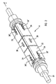
- the drive shaft unit 14 comprises a drive shaft 20 made by one of two U-shaped pieces composite housing 22 is enclosed.
- the Housing 22 has cutouts 24 for receiving on the shaft circumference distributed guide fins 26, 26 '.
- the drive shaft unit 14 is both thermal as well as particularly stable against mechanical loads. Due to the arrangement of the drive shaft 20 within the housing 22 is the total mass of the drive shaft unit 14 and thus their thermal inertia is particularly low. At a Heating or cooling of the drive shaft unit 14 due to a change in their environment, for example with a load change of the gas turbine, the housing is first 22 warmed or cooled. Only then is the drive shaft delayed 20 also heated or cooled. Because of a Such a delay results in thermal expansion or contraction in the housing 22 earlier than in the drive shaft 20. To avoid possibly resulting from it thermal stresses between the housing 22 and the drive shaft 20 is the second set of guide fins 26 'in the recesses 24 assigned to them in the longitudinal direction X the drive shaft 20 slidably mounted.
- the drive shaft unit Due to the design of the housing 22, the drive shaft unit has 14 due to its high torsional strength particularly high mechanical strength.
- the drive shaft unit 14 is thus also in a one-sided arrangement of a servomotor particularly safe and reliable and has a long lifespan.
Landscapes
- Engineering & Computer Science (AREA)
- General Engineering & Computer Science (AREA)
- Mechanical Engineering (AREA)
- Chemical & Material Sciences (AREA)
- Combustion & Propulsion (AREA)
- Engine Equipment That Uses Special Cycles (AREA)
- Supercharger (AREA)
- Shafts, Cranks, Connecting Bars, And Related Bearings (AREA)
Claims (2)
- Unité (14) à arbre d'entraínement pour un volet (12) de gaz d'échappement dans le canal (4) de gaz d'échappement d'une turbine à gaz, comprenant une enveloppe (22) entourant un arbre (20) d'entraínement qui a des évidements (24) de réception d'ailettes (26, 26') de guidage réparties sur le pourtour de l'arbre, un premier jeu d'ailettes (26) de guidage étant relié rigidement à l'enveloppe (22) et un deuxième jeu d'ailettes (26') de guidage pouvant coulisser dans la direction X longitudinale de l'arbre d'entraínement dans les évidements (24) qui leur sont associés.
- Unité à arbre d'entraínement suivant la revendication 1, dont l'enveloppe (22) est composée de deux pièces profilées en U.
Applications Claiming Priority (2)
| Application Number | Priority Date | Filing Date | Title |
|---|---|---|---|
| DE19620823 | 1996-05-23 | ||
| DE19620823A DE19620823C1 (de) | 1996-05-23 | 1996-05-23 | Antriebswelleneinheit für eine Rauchgasklappe |
Publications (3)
| Publication Number | Publication Date |
|---|---|
| EP0809073A2 EP0809073A2 (fr) | 1997-11-26 |
| EP0809073A3 EP0809073A3 (fr) | 1999-03-03 |
| EP0809073B1 true EP0809073B1 (fr) | 2001-12-19 |
Family
ID=7795147
Family Applications (1)
| Application Number | Title | Priority Date | Filing Date |
|---|---|---|---|
| EP97107877A Expired - Lifetime EP0809073B1 (fr) | 1996-05-23 | 1997-05-14 | Assemblage d'un arbre de transmission |
Country Status (3)
| Country | Link |
|---|---|
| EP (1) | EP0809073B1 (fr) |
| DE (2) | DE19620823C1 (fr) |
| TW (1) | TW327203B (fr) |
Family Cites Families (4)
| Publication number | Priority date | Publication date | Assignee | Title |
|---|---|---|---|---|
| DE834168C (de) * | 1944-05-10 | 1952-03-17 | Gustav Friedrich Gerdts | Absperrventil mit Klappenverschluss |
| DE1049524B (de) * | 1956-07-24 | 1959-01-29 | Babcock & Wilcox Dampfkessel | Mehrteilige Klappe, insbesondere Rauchgasklappe |
| JPS59121217A (ja) * | 1982-12-27 | 1984-07-13 | Canon Inc | 回転体の駆動軸 |
| DE3637734A1 (de) * | 1986-11-05 | 1988-05-11 | Pks Engineering | Vorrichtung zum absperren grosser heissgas-rohrleitungen |
-
1996
- 1996-05-23 DE DE19620823A patent/DE19620823C1/de not_active Expired - Fee Related
-
1997
- 1997-05-14 TW TW086106405A patent/TW327203B/zh active
- 1997-05-14 DE DE59705845T patent/DE59705845D1/de not_active Expired - Lifetime
- 1997-05-14 EP EP97107877A patent/EP0809073B1/fr not_active Expired - Lifetime
Also Published As
| Publication number | Publication date |
|---|---|
| EP0809073A2 (fr) | 1997-11-26 |
| TW327203B (en) | 1998-02-21 |
| DE59705845D1 (de) | 2002-01-31 |
| DE19620823C1 (de) | 1997-11-27 |
| EP0809073A3 (fr) | 1999-03-03 |
Similar Documents
| Publication | Publication Date | Title |
|---|---|---|
| EP3186498B1 (fr) | Ensemble de turbine à gaz | |
| EP1071871B1 (fr) | Turbine de turbosoufflante a gaz d'echappement | |
| DE602004009487T2 (de) | Dämpfungs- und Dichtungselement für Turbine | |
| DE19821889B4 (de) | Verfahren und Vorrichtung zur Durchführung von Reparatur- und/oder Wartungsarbeiten im Innengehäuse einer mehrschaligen Turbomaschine | |
| EP0289697A1 (fr) | Dispositif de commande d'aubes de guidage à calage variable pour turbomachine axiale | |
| EP0555719B1 (fr) | Procédé et installation pour la reduction des oxydes d'azote dans les gaz d'échappement | |
| DE2618600A1 (de) | Schubduese mit variabler flaeche | |
| EP1636526A1 (fr) | Chambre a combustion | |
| EP2455584A1 (fr) | Turbine à gaz avec des moyens de contrôle de refroidisment comprenant partialement des alliages à mémoire de forme | |
| EP1954922B1 (fr) | Turbine a vapeur a entretoises porteuses | |
| EP1268981B1 (fr) | Installation de turbine | |
| EP0828058B1 (fr) | Elément d'un canal de gaz d'échappement d'une turbine à gaz | |
| EP0809073B1 (fr) | Assemblage d'un arbre de transmission | |
| DE112009003129B4 (de) | Gasturbine mit einer schaltbaren Solarheizeinrichtung | |
| EP1028228A1 (fr) | Dispositif de refroidissement de plate-forme d'aube rotorique de turbine | |
| EP1423586B1 (fr) | Piece intercalaire de chambre de combustion de turbine a gaz | |
| WO1994029643A1 (fr) | Systeme de turbine a gaz pourvu en aval d'un generateur de vapeur utilisant la chaleur perdue | |
| EP1422479B1 (fr) | Chambre pour la combustion d' un mélange combustible fluide | |
| EP1744014A1 (fr) | Agencement de montage des aubes d'entrée d'une turbine à gaz | |
| EP1284392A1 (fr) | Chambre de combustion | |
| DE102018216408A1 (de) | Abgasleiteinrichtung für einen Abgasturbolader, Abgasturbolader und Verfahren zur Herstellung der Abgasleiteinrichtung | |
| EP0873467A2 (fr) | Systeme de paliers pour ensemble de turbomachines | |
| DE10233881B4 (de) | Durch thermische Effekte radial veränderbares Ringelement | |
| DE3316070A1 (de) | Gasturbinenaggregat | |
| EP1710399B1 (fr) | Système de déplacement, paire de turbines, ensemble de turbines et méthode de transmission d'un changement de position entre deux turbines |
Legal Events
| Date | Code | Title | Description |
|---|---|---|---|
| PUAI | Public reference made under article 153(3) epc to a published international application that has entered the european phase |
Free format text: ORIGINAL CODE: 0009012 |
|
| AK | Designated contracting states |
Kind code of ref document: A2 Designated state(s): CH DE ES FR GB LI SE |
|
| PUAL | Search report despatched |
Free format text: ORIGINAL CODE: 0009013 |
|
| AK | Designated contracting states |
Kind code of ref document: A3 Designated state(s): CH DE ES FR GB LI SE |
|
| 17P | Request for examination filed |
Effective date: 19990406 |
|
| GRAG | Despatch of communication of intention to grant |
Free format text: ORIGINAL CODE: EPIDOS AGRA |
|
| GRAG | Despatch of communication of intention to grant |
Free format text: ORIGINAL CODE: EPIDOS AGRA |
|
| GRAH | Despatch of communication of intention to grant a patent |
Free format text: ORIGINAL CODE: EPIDOS IGRA |
|
| GRAH | Despatch of communication of intention to grant a patent |
Free format text: ORIGINAL CODE: EPIDOS IGRA |
|
| GRAH | Despatch of communication of intention to grant a patent |
Free format text: ORIGINAL CODE: EPIDOS IGRA |
|
| 17Q | First examination report despatched |
Effective date: 20010607 |
|
| GRAH | Despatch of communication of intention to grant a patent |
Free format text: ORIGINAL CODE: EPIDOS IGRA |
|
| GRAA | (expected) grant |
Free format text: ORIGINAL CODE: 0009210 |
|
| AK | Designated contracting states |
Kind code of ref document: B1 Designated state(s): CH DE ES FR GB LI SE |
|
| REG | Reference to a national code |
Ref country code: CH Ref legal event code: EP |
|
| REG | Reference to a national code |
Ref country code: GB Ref legal event code: IF02 |
|
| REF | Corresponds to: |
Ref document number: 59705845 Country of ref document: DE Date of ref document: 20020131 |
|
| PG25 | Lapsed in a contracting state [announced via postgrant information from national office to epo] |
Ref country code: SE Free format text: LAPSE BECAUSE OF FAILURE TO SUBMIT A TRANSLATION OF THE DESCRIPTION OR TO PAY THE FEE WITHIN THE PRESCRIBED TIME-LIMIT Effective date: 20020319 |
|
| GBT | Gb: translation of ep patent filed (gb section 77(6)(a)/1977) |
Effective date: 20020325 |
|
| PG25 | Lapsed in a contracting state [announced via postgrant information from national office to epo] |
Ref country code: LI Free format text: LAPSE BECAUSE OF NON-PAYMENT OF DUE FEES Effective date: 20020531 Ref country code: CH Free format text: LAPSE BECAUSE OF NON-PAYMENT OF DUE FEES Effective date: 20020531 |
|
| ET | Fr: translation filed | ||
| PG25 | Lapsed in a contracting state [announced via postgrant information from national office to epo] |
Ref country code: ES Free format text: LAPSE BECAUSE OF FAILURE TO SUBMIT A TRANSLATION OF THE DESCRIPTION OR TO PAY THE FEE WITHIN THE PRESCRIBED TIME-LIMIT Effective date: 20020627 |
|
| PLBE | No opposition filed within time limit |
Free format text: ORIGINAL CODE: 0009261 |
|
| STAA | Information on the status of an ep patent application or granted ep patent |
Free format text: STATUS: NO OPPOSITION FILED WITHIN TIME LIMIT |
|
| 26N | No opposition filed | ||
| REG | Reference to a national code |
Ref country code: CH Ref legal event code: PL |
|
| REG | Reference to a national code |
Ref country code: FR Ref legal event code: PLFP Year of fee payment: 19 |
|
| PGFP | Annual fee paid to national office [announced via postgrant information from national office to epo] |
Ref country code: GB Payment date: 20150511 Year of fee payment: 19 |
|
| PGFP | Annual fee paid to national office [announced via postgrant information from national office to epo] |
Ref country code: FR Payment date: 20150513 Year of fee payment: 19 |
|
| PGFP | Annual fee paid to national office [announced via postgrant information from national office to epo] |
Ref country code: DE Payment date: 20150720 Year of fee payment: 19 |
|
| REG | Reference to a national code |
Ref country code: DE Ref legal event code: R119 Ref document number: 59705845 Country of ref document: DE |
|
| GBPC | Gb: european patent ceased through non-payment of renewal fee |
Effective date: 20160514 |
|
| REG | Reference to a national code |
Ref country code: FR Ref legal event code: ST Effective date: 20170131 |
|
| PG25 | Lapsed in a contracting state [announced via postgrant information from national office to epo] |
Ref country code: DE Free format text: LAPSE BECAUSE OF NON-PAYMENT OF DUE FEES Effective date: 20161201 Ref country code: FR Free format text: LAPSE BECAUSE OF NON-PAYMENT OF DUE FEES Effective date: 20160531 |
|
| PG25 | Lapsed in a contracting state [announced via postgrant information from national office to epo] |
Ref country code: GB Free format text: LAPSE BECAUSE OF NON-PAYMENT OF DUE FEES Effective date: 20160514 |