EP0808976B1 - Self-locking emergency lock - Google Patents
Self-locking emergency lock Download PDFInfo
- Publication number
- EP0808976B1 EP0808976B1 EP97102645A EP97102645A EP0808976B1 EP 0808976 B1 EP0808976 B1 EP 0808976B1 EP 97102645 A EP97102645 A EP 97102645A EP 97102645 A EP97102645 A EP 97102645A EP 0808976 B1 EP0808976 B1 EP 0808976B1
- Authority
- EP
- European Patent Office
- Prior art keywords
- lock
- lever
- slide
- self
- changeover part
- Prior art date
- Legal status (The legal status is an assumption and is not a legal conclusion. Google has not performed a legal analysis and makes no representation as to the accuracy of the status listed.)
- Expired - Lifetime
Links
- 238000006073 displacement reaction Methods 0.000 claims description 3
- 238000010168 coupling process Methods 0.000 abstract description 4
- 230000008878 coupling Effects 0.000 abstract description 3
- 238000005859 coupling reaction Methods 0.000 abstract description 3
- 230000008859 change Effects 0.000 description 4
- 230000003111 delayed effect Effects 0.000 description 4
- 230000002426 anti-panic effect Effects 0.000 description 2
- 230000008901 benefit Effects 0.000 description 2
- 230000006978 adaptation Effects 0.000 description 1
- 238000010276 construction Methods 0.000 description 1
- 238000005516 engineering process Methods 0.000 description 1
- 230000007717 exclusion Effects 0.000 description 1
- 230000007246 mechanism Effects 0.000 description 1
- 238000000034 method Methods 0.000 description 1
- 230000008569 process Effects 0.000 description 1
Images

Classifications
-
- E—FIXED CONSTRUCTIONS
- E05—LOCKS; KEYS; WINDOW OR DOOR FITTINGS; SAFES
- E05B—LOCKS; ACCESSORIES THEREFOR; HANDCUFFS
- E05B63/00—Locks or fastenings with special structural characteristics
- E05B63/16—Locks or fastenings with special structural characteristics with the handles on opposite sides moving independently
-
- E—FIXED CONSTRUCTIONS
- E05—LOCKS; KEYS; WINDOW OR DOOR FITTINGS; SAFES
- E05B—LOCKS; ACCESSORIES THEREFOR; HANDCUFFS
- E05B59/00—Locks with latches separate from the lock-bolts or with a plurality of latches or lock-bolts
-
- E—FIXED CONSTRUCTIONS
- E05—LOCKS; KEYS; WINDOW OR DOOR FITTINGS; SAFES
- E05B—LOCKS; ACCESSORIES THEREFOR; HANDCUFFS
- E05B63/00—Locks or fastenings with special structural characteristics
- E05B63/18—Locks or fastenings with special structural characteristics with arrangements independent of the locking mechanism for retaining the bolt or latch in the retracted position
- E05B63/20—Locks or fastenings with special structural characteristics with arrangements independent of the locking mechanism for retaining the bolt or latch in the retracted position released automatically when the wing is closed
-
- E—FIXED CONSTRUCTIONS
- E05—LOCKS; KEYS; WINDOW OR DOOR FITTINGS; SAFES
- E05B—LOCKS; ACCESSORIES THEREFOR; HANDCUFFS
- E05B65/00—Locks or fastenings for special use
- E05B65/10—Locks or fastenings for special use for panic or emergency doors
- E05B65/1086—Locks with panic function, e.g. allowing opening from the inside without a ley even when locked from the outside
-
- E—FIXED CONSTRUCTIONS
- E05—LOCKS; KEYS; WINDOW OR DOOR FITTINGS; SAFES
- E05B—LOCKS; ACCESSORIES THEREFOR; HANDCUFFS
- E05B15/00—Other details of locks; Parts for engagement by bolts of fastening devices
- E05B15/10—Bolts of locks or night latches
- E05B15/102—Bolts having movable elements
- E05B2015/105—Two pivoting latch elements with opposite inclined surfaces mounted on one slidable main latch-piece
-
- E—FIXED CONSTRUCTIONS
- E05—LOCKS; KEYS; WINDOW OR DOOR FITTINGS; SAFES
- E05B—LOCKS; ACCESSORIES THEREFOR; HANDCUFFS
- E05B63/00—Locks or fastenings with special structural characteristics
- E05B63/18—Locks or fastenings with special structural characteristics with arrangements independent of the locking mechanism for retaining the bolt or latch in the retracted position
- E05B63/20—Locks or fastenings with special structural characteristics with arrangements independent of the locking mechanism for retaining the bolt or latch in the retracted position released automatically when the wing is closed
- E05B2063/207—Automatic deadlocking
Definitions
- the invention relates to a self-locking panic lock with a spring-loaded Cross latch, a slide-controlled bolt, one in the longitudinal direction the lock can be moved using a key Slider and one locking the slider when the bolt is closed spring-loaded control part and with a follower, which has a panic lever actuating the slide, the lock set up has a sliding interchangeable part over which the nut halves are optionally connectable and end-connectable, and that the interchangeable part in its respective end position opposite the lock plate is locked.
- the object of the invention is a self-locking panic lock to further develop the type mentioned at the beginning with reference to the switchover function. This is said to be due in particular to advantageous structural features narrow locks, i.e. in so-called tubular frame locks be made possible.
- the switching technology according to the invention should also be used in such self-locking panic locks can find which with a device for delayed advance of the bolt are provided.
- the invention solves this problem by teaching according to claim 1.
- the locking of an interchangeable part in its respective End position enables simple construction of the operating mechanism, i.e. the exchangeable part does not have to be constantly loaded by the exchangeable part Components are held in their respective positions.
- the interchangeable part within the lock housing for the coupling process or decoupling process only by a relatively small amount must be moved, there is the advantage that the unlocking the door (dead bolt lock) and switching, i.e. connecting two nut halves over the interchangeable part, with a single key movement can be done.
- the switching wedges When the interchangeable part is actuated, the switching wedges "skip" with their wedge surfaces each arranged on the lock plate Guide cams and thus place the interchangeable part in the respective Position opposite the lock plate.
- the switching wedges receiving recess in Interchangeable part through a cover plate closing the recess covered, in particular the spring that spreads the switching wedges to secure their position
- claims 3 and 4 are a lock lever on the lock plate and a switch lever mounted, which by key operation (Lock cylinder bit) can be acted upon, by means of the switch lever the interchangeable part is moved so that the nut halves are coupled and the change part is moved using the switch-off lever will be that the coupling of the nut halves is released.
- the switch-off lever has two arms Lever trained.
- Both the on lever and the off lever are operated using the Lock cylinder bit actuated; they act alternately on you switching cams arranged on the interchangeable part.
- an intermediate lever which is rotatable on Lock plate stored and arranged by one on the interchangeable part Switch cam is pivotable.
- This intermediate lever is activated of the switch lever pivoted through the lock cylinder bit and in turn actuates a pivotally mounted on the handle follower Switch lever that couples the nut halves together.
- the switch-off lever i.e. in the event of a shift of the The intermediate lever disengages from the change lever, so that the two nut halves are decoupled.
- the invention is basically applicable to all mortise locks; it is characterized by a simple structure and in particular advantageous use in narrow locks with limited Space as well as in particular with such self-locking Panic locks, in which an appropriate slide lock by means of a control trap and an additional control part delayed locking lock when closing the door is possible.
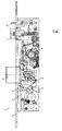
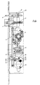
- FIG. 1 shows the panic lock, generally designated 1, the essential components of a lock plate 2, a faceplate 3, a slide 5, a bolt 6, a cross latch 7, a control part 8, a follower 9, a change part 12, a switch lever 14 and a switch lever 15 are.
- the bolt 6 is locked, i.e. the Slider 5 is in its lower position.
- the one on the Locking cylinder contour 4 moving cylinder bit 18 has its Home position 18 'moves against a stop 29 of the slide 5.
- a stop edge 25 the slide 5 on a pin 20 of a cross shaft 19 of the Cross trap 7.
- the cross trap 7 is locked against inference.
- the cross trap can 7 also not the control part 8 via a contact with the cross latch 7 Push back bolt extension 24 of the control part 8.
- the one sliding in corresponding guides, not specified Slider 5 also locks the latch 6 in its lower position a mandrel 28 of the bolt 6.
- the interchangeable part 12 is also located in its lower position. The door can only be pressed 9 and the panic levers 11, 11 '- by means of which the slide 5 can be moved - be opened.
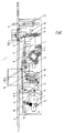
- the slide 5 is by means of the cylinder bit 18 over the Stop 29 has been moved up in the image plane; is there the bolt 6 in a known manner via a slot 26 in the slide 5th has been closed and has 45 with its slide edge Stop cam 40 of the interchangeable part 12 and thus the interchangeable part 12 in the image layer shifted to the right.
- a hook-like extension arranged in the upper region of the slide 5 23 grips a holding cam 22 on the control part 8, so that the Slider 5 - seen in the image plane - prevented from moving downwards is.
- the pin 20 is on the cross shaft 19 in a position opposite the slot 21 on the slide 5.
- a return spring 30 of the slide 5 is now cocked.
Landscapes
- Engineering & Computer Science (AREA)
- Structural Engineering (AREA)
- Business, Economics & Management (AREA)
- Emergency Management (AREA)
- Lock And Its Accessories (AREA)
- Moulds, Cores, Or Mandrels (AREA)
- Manufacturing Of Tubular Articles Or Embedded Moulded Articles (AREA)
Abstract
Description
Die Erfindung betrifft ein selbstverriegelndes Panikschloß mit einer federbelasteten Kreuzfalle, einem schiebergesteuerten Riegel, einem in Längsrichtung des Schlosses mittels einer Schlüsselbetätigung bewegbaren Schieber und einem den Schieber bei rückgeschlossenem Riegel arretierenden federbelasteten Steuerteil sowie mit einer Drückernuß, welche einen den Schieber betätigenden Panikhebel aufweist, wobei das Schloß eingerichte ein verschiebbares Wechselteil aufweist, über das die Nußhälften wahlweise kuppelbar und endkuppelbar sind, und dass das Wechselteil in seiner jeweiligen Endposition gegenüber dem Schloßblech arretiert ist.The invention relates to a self-locking panic lock with a spring-loaded Cross latch, a slide-controlled bolt, one in the longitudinal direction the lock can be moved using a key Slider and one locking the slider when the bolt is closed spring-loaded control part and with a follower, which has a panic lever actuating the slide, the lock set up has a sliding interchangeable part over which the nut halves are optionally connectable and end-connectable, and that the interchangeable part in its respective end position opposite the lock plate is locked.
Die DE 36 36 237 A1 beschreibt ein mittels eines Schließbartes betätigbares Panikschloß der eingangs genannten Gattung mit einer geteilten Schloßnuß, bei der an der Türinnenseite und an der Türaußenseite jeweils eine Drehhandhabe angeordnet ist. Ausgehend von der Panikfunktion, bei der nur die Drehhandhabe an der Türinnenseite wirksam ist, kann eine Umschaltung erfolgen, wobei mittels eines vom Schließbart betätigten Schiebers und eines an der Schloßnuß angeschlossenen Kupplungshebels die Nußhälften gekuppelt werden können, so dass auch die an der Außenseite der Tür angeordnete Drehhandhabe wirksam ist. Beim Öffnungsvorgang der Tür wird die Kupplung selbstätig aufgehoben.DE 36 36 237 A1 describes an actuatable by means of a lock bit Panic lock of the type mentioned above with a divided Lock nut, on the inside and outside of the door a rotating handle is arranged. Starting from the Panic function, in which only the turning handle on the inside of the door is effective, a switchover can take place, whereby by means of Lock bit actuated slide and one connected to the lock nut Clutch lever the nut halves can be coupled, so that the rotating handle located on the outside of the door is effective. When the door is opened, the coupling becomes automatic canceled.
Die DE 37 36 592 A1 beschreibt ein Schlüsselbetätigtes Rohrrahmenschloß mit Antipanikfunktion, bei dem für die Antipanikfunktion relevanten Bauteile entsprechend einer vorbestimmbaren Fluchtrichtung im Schloß angewendet werden können. Für die Umschaltung auf die Panikfunktion ist eine geteilte Nuß vorgesehen, wobei zur Anpassung an die vorbestimmbare Fluchtrichtung unterschiedliche Schaltscheiben Verwendung finden. DE 37 36 592 A1 describes a key-operated tubular frame lock with anti-panic function, with the relevant for the anti-panic function Components according to a predeterminable escape direction in the castle can be applied. For switching to the panic function a split nut is provided, with adaptation to the predeterminable Direction of escape different switching discs use Find.
Durch die DE A 39 38 655 ist ein selbstverriegelndes Panikschloß bekannt geworden, dessen Schieber motorisch oder mechanisch bewegt werden kann. Außer dem Schloßriegel und der als Kreuzfalle ausgebildeten Schloßfalle ist ein Steuerteil vorgesehen, mit welchem der Schieber bei rückgeschlossenem Riegel in seiner oberen, die Kreuzfalle freigebenden Position gehalten werden kann. Mit der einteiligen Drückernuß ist weiter ein als Folgeglied bezeichneter Hebel verbunden, über den der Schieber und damit der Riegel betätigt und die Tür von der Innenseite her geöffnet werden kann (Panikfunktion). Das Schloßeingerichte des vorbeschriebenen Schlosses sieht keine Bauteile vor, mit denen es möglich ist, die Tür durch Drückerbetätigung auch von außen zu öffnen.From DE A 39 38 655 a self-locking panic lock is known become, whose slide moves motor or mechanical can be. Except for the lock bolt and the cross latch A latch part is provided with which the slide with the bolt locked in its upper, releasing the cross latch Position can be held. With the one-piece follower is further connected to a lever called a follower, via which the Slider and thus the bolt operated and the door from the inside can be opened (panic function). The lock set up of the above Lock does not provide any components with which it is possible the door can also be opened from the outside by pressing the handle.
Eine ebenfalls geteilte Nuß beschreibt die DE 35 21 213 A1 für ein Fallenpanikschloß, insbesondere für Rohrrahmentüren.DE 35 21 213 A1 also describes a split nut Trap panic lock, especially for tubular frame doors.
Aufgabe der Erfindung ist es, ein selbstverriegelndes Panikschloß der eingangs genannten Gattung mit Bezug auf die Umschaltfunktion weiterzubilden. Dies soll insbesondere durch vorteilhafte bauliche Merkmale bei schmalbauenden Schlössern, d.h. bei sogenannten Rohrrahmenschlössern ermöglicht werden. Die erfindungsgemäße Umschalttechnik soll auch in solchen selbstverriegelnden Panikschlössern Anwendung finden können, welche mit einer Vorrichtung zum verzögerten Vorschluß des Riegels versehen sind.The object of the invention is a self-locking panic lock to further develop the type mentioned at the beginning with reference to the switchover function. This is said to be due in particular to advantageous structural features narrow locks, i.e. in so-called tubular frame locks be made possible. The switching technology according to the invention should also be used in such self-locking panic locks can find which with a device for delayed advance of the bolt are provided.
Die Erfindung löst die gestellte Aufgabe durch die Lehre nach Anspruch 1. Insbesondere die Arretierung eines Wechselteils in seiner jeweiligen Endposition ermöglicht einen einfachen Aufbau der Bedienungsmechanik, d.h. das Wechselteil muß nicht durch ständig das Wechselteil beaufschlagende Bauteile in seiner jeweiligen Position gehalten werden. Da das Wechselteil innerhalb des Schloßgehäuses für den Kopplungsvorgang bzw. Entkopplungsvorgang nur um einen relativ geringen Betrag verschoben werden muß, ergibt sich der Vorteil, daß das Aufschließen der Tür (Riegelrückschluß) und das Umschalten, d.h. das Verbinden zweier Nußhälften über das Wechselteil, mit einer einzigen Schlüsselbewegung erfolgen kann. The invention solves this problem by teaching according to claim 1. In particular the locking of an interchangeable part in its respective End position enables simple construction of the operating mechanism, i.e. the exchangeable part does not have to be constantly loaded by the exchangeable part Components are held in their respective positions. There the interchangeable part within the lock housing for the coupling process or decoupling process only by a relatively small amount must be moved, there is the advantage that the unlocking the door (dead bolt lock) and switching, i.e. connecting two nut halves over the interchangeable part, with a single key movement can be done.
Bei der Betätigung des Wechselteils "überspringen" die Schaltkeile jeweils mit Ihren Keilflächen die am Schlossblech angeordneten Führungsnocken und legen somit das Wechselteil in der jeweiligen Position gegenüber dem Schlossblech fest.When the interchangeable part is actuated, the switching wedges "skip" with their wedge surfaces each arranged on the lock plate Guide cams and thus place the interchangeable part in the respective Position opposite the lock plate.
Weitere Merkmale der Erfindung sind durch die Unteransprüche gekennzeichnet.Further features of the invention are characterized by the subclaims.
Gemäß Anspruch 2 ist die die Schaltkeile aufnehmende Ausnehmung im
Wechselteil durch ein die Ausnehmung verschließendes Abdeckblech
abgedeckt, um insbesondere die die Schaltkeile spreitzende Feder in
ihrer Position zu sichernAccording to
Gemäß den Ansprüchen 3 und 4 sind am Schloßblech ein Einschalthebel
und ein Ausschalthebel gelagert, welche durch Schlüsselbetätigung
(Schließzylinderbart) beaufschlagt werden können, wobei mittels des Einschalthebels
das Wechselteil so bewegt wird, daß die Nußhälften gekoppelt
werden und mittels des Ausschalthebels das Wechselteil so bewegt
wird, daß die Kopplung der Nußhälften aufgehoben wird.According to
In Ausgestaltung der Erfindung ist der Ausschalthebel als zweiarmiger Hebel ausgebildet.In an embodiment of the invention, the switch-off lever has two arms Lever trained.
Sowohl Einschalthebel als auch Ausschalthebel werden mittels des Schließzylinderbartes betätigt; sie wirken dabei wechselweise auf einen am Wechselteil angeordneten Schaltnocken.Both the on lever and the off lever are operated using the Lock cylinder bit actuated; they act alternately on you switching cams arranged on the interchangeable part.
An der dem Schließzylinder und damit dem Einschalthebel bzw. dem Ausschalthebel gegenüberliegenden Seite des Wechselteils ist im Bereich der Drückernuß ein Zwischenhebel angeordnet, welcher drehbar am Schloßblech gelagert und von einem am Wechselteil angeordneten Schaltnocken verschwenkbar ist. Dieser Zwischenhebel wird bei Betätigung des Einschalthebels durch den Schließzylinderbart verschwenkt und betätigt seinerseits einen an der Drückernuß schwenkbar gelagerten Umschalthebel, welcher die Nußhälften miteinander koppelt. Bei Betätigung des Ausschalthebels, d.h. bei dadurch bedingter Verschiebung des Wechselteils gerät der Zwischenhebel außer Eingriff mit dem Umschalthebel, so daß die beiden Nußhälften entkoppelt werden.On the lock cylinder and thus the switch lever or switch lever opposite side of the interchangeable part is in the area the follower arranged an intermediate lever, which is rotatable on Lock plate stored and arranged by one on the interchangeable part Switch cam is pivotable. This intermediate lever is activated of the switch lever pivoted through the lock cylinder bit and in turn actuates a pivotally mounted on the handle follower Switch lever that couples the nut halves together. When actuated the switch-off lever, i.e. in the event of a shift of the The intermediate lever disengages from the change lever, so that the two nut halves are decoupled.
Wie vorerwähnt, kann die Betätigung des Schiebers im Sinne "Riegelrückschluß" und die Betätigung des das Wechselteil verschiebenden Einschalthebels mit einer einzigen Schlüsselbewegung erfolgen. Dabei hat es sich als besonders vorteilhaft erwiesen, den vom Schließzylinderbart betätigten Anschlag des Einschalthebels so in die Rotationskurve des Schließzylinderbartes einfassen zu lassen, daß bei einer vorbestimmten Stellung des Schließzylinderbartes, die durch einen Begrenzungsnocken der Schließzylinderkontur festgelegt ist, sowohl der Schieber als auch der Einschalthebel in ihrer oberen Position durch den Schließzylinderbart abgestützt und damit arretiert werden. Bei dieser Schlüsselstellung ergibt sich überraschenderweise der Vorteil einer sogenannten "Dauerauf-Funktion", d.h. die Funktion der Selbstverriegelung ist aufgehoben, was bedeutet, daß beim Schließen der Tür der Riegel nicht ausgeschlossen wird. Diese Funktion kann insbesondere dann vorteilhaft sein, wenn Material durch die Tür transportiert werden soll, ohne daß eine Drückerbetätigung erforderlich ist.As mentioned above, the actuation of the slide in the sense of "bolt back yoke" and the actuation of the switching lever shifting the change part with a single key movement. Doing it turned out to be particularly advantageous that the lock cylinder bit actuated stop of the switch lever in the rotation curve of the Lock cylinder must have a border that at a predetermined Position of the lock cylinder bit by a limiting cam the lock cylinder contour is fixed, both the slide and the Switch-on lever in its upper position through the lock cylinder bit supported and thus locked. With this key position results surprisingly, the advantage of a so-called "continuous open function", i.e. the self-locking function is canceled what means that when the door is closed the bolt is not excluded becomes. This function can be particularly advantageous if Material is to be transported through the door without having to press a button is required.
Die Erfindung ist grundsätzlich bei allen Einsteckschlössern anwendbar; sie kennzeichnet sich durch einen einfachen Aufbau sowie insbesondere vorteilhafter Verwendung bei schmalbauenden Schlössern mit beschränkten Platzverhältnissen sowie insbesondere bei solchen selbstverriegelnden Panikschlössern aus, bei denen durch eine entsprechende Schieberarretierung mittels einer Steuerfalle und einem zusätzlichen Steuerteil ein verzögerter Riegelvorschluß beim Schließen der Tür möglich ist.The invention is basically applicable to all mortise locks; it is characterized by a simple structure and in particular advantageous use in narrow locks with limited Space as well as in particular with such self-locking Panic locks, in which an appropriate slide lock by means of a control trap and an additional control part delayed locking lock when closing the door is possible.
Die Erfindung wird nachfolgend anhand eines möglichen Ausführungsbeispieles näher erläutert. Es zeigen:
- Figur 1:
- eine Ansicht auf das Schloßeingerichte bei abgenommener Schloßdecke
- Figur 2:
- eine Ansicht gemäß Figur 1 bei vorgeschlossenem Riegel unter Weglassung einiger für die Erfindung unwesentlicher oder bekannter Bauteile
- Figur 3:
- eine Ansicht gemäß
Figur 2 bei rückgeschlossenem Riegel - Figur 4:
- eine Ansicht gemäß
Figur 3 unter Fortlassung des Schiebers bei gekoppelten Nußhälften - Figur 5:
- eine Ansicht gemäß
Figur 4 mit Darstellung des Schiebers bei entkoppelten Nußhälften - Figur 6:
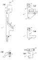
- den Schieber
- Figur 7:
- das Wechselteil
- Figur 8:
- das Abdeckblech
- Figur 9:
- die Panikhebel
- Figur 10:
- das Steuerteil
- Figur 11:
- den Zwischenhebel
- Figur 12:
- den Umschalthebel
- Figur 13:
- den Einschalthebel
- Figur 14:
- den Ausschalthebel
- Figure 1:
- a view of the castle furnishings with the castle ceiling removed
- Figure 2:
- a view according to Figure 1 with the bolt locked, omitting some components which are insignificant or known for the invention
- Figure 3:
- a view of Figure 2 with the bolt closed
- Figure 4:
- a view of Figure 3 omitting the slide with coupled nut halves
- Figure 5:
- a view of Figure 4 showing the slide with decoupled nut halves
- Figure 6:
- the slider
- Figure 7:
- the interchangeable part
- Figure 8:
- the cover plate
- Figure 9:
- the panic levers
- Figure 10:
- the control section
- Figure 11:
- the intermediate lever
- Figure 12:
- the switch lever
- Figure 13:
- the switch lever
- Figure 14:
- the switch-off lever
In der Figur 1 ist das allgemein mit 1 bezeichnete Panikschloß dargestellt,
dessen wesentliche Bauteile ein Schloßblech 2, eine Stulp 3, ein Schieber
5, ein Riegel 6, eine Kreuzfalle 7, ein Steuerteil 8, eine Drückernuß 9,
ein Wechselteil 12, ein Einschalthebel 14 und ein Ausschalthebel 15 sind.1 shows the panic lock, generally designated 1,
the essential components of a
Im folgenden wird die Funktion des selbstverriegelnden Panikschlosses anhand der weiteren Zeichnungen beschrieben.The following is the function of the self-locking panic lock described with reference to the other drawings.
In der Darstellung nach Figur 2 ist der Riegel 6 vorgeschlossen, d.h. der
Schieber 5 befindet sich in seiner unteren Position. Der sich auf der
Schließzylinderkontur 4 bewegende Zylinderbart 18 hat sich von seiner
Grundstellung 18' gegen einen Anschlag 29 des Schiebers 5 bewegt. Bei
der dargestellten Position des Schiebers 5 liegt eine Anschlagkante 25
des Schiebers 5 an einem Zapfen 20 eines Kreuzfallenschaftes 19 der
Kreuzfalle 7 an. In dieser Situation ist die Tür geschlossen; die Kreuzfalle
7 ist gegen Rückschließen gesperrt. Infolgedessen vermag die Kreuzfalle
7 auch nicht das Steuerteil 8 über einen an der Kreuzfalle 7 anliegenden
Riegelfortsatz 24 des Steuerteils 8 zurückzudrücken.In the illustration according to FIG. 2, the
Der in entsprechenden, nicht näher bezeichneten Führungen gleitende
Schieber 5 sperrt in seiner unteren Position ebenfalls den Riegel 6 über
einen Dorn 28 des Riegels 6. Das Wechselteil 12 befindet sich ebenfalls
in seiner unteren Position. Die Tür kann lediglich über die Drückemuß 9
und die Panikhebel 11, 11' - mit deren Hilfe der Schieber 5 bewegbar ist -
geöffnet werden.The one sliding in corresponding guides, not specified
In der Figur 3 ist der Schieber 5 mittels des Zylinderbartes 18 über den
Anschlag 29 in der Bildebene nach oben verschoben worden; dabei ist
der Riegel 6 in bekannter Weise über einen Schlitz 26 im Schieber 5
rückgeschlossen worden und hat dabei mit seiner Schieberkante 45 den
Anschlagnocken 40 des Wechselteils 12 und damit das Wechselteil 12 in
der Bildebene nach rechts verschoben.In Figure 3, the
Ein im oberen Bereich des Schiebers 5 angeordneter hakenartiger Fortsatz
23 hinterfaßt dabei einen Haltenocken 22 am Steuerteil 8, so daß der
Schieber 5 - in der Bildebene gesehen - an einer Abwärtsbewegung gehindert
ist. Gleichzeitig befindet sich der Zapfen 20 am Kreuzfallenschaft
19 in einer Position gegenüber dem Schlitz 21 am Schieber 5. Eine Rückholfeder
30 des Schiebers 5 ist nunmehr gespannt.A hook-like extension arranged in the upper region of the
Es ist ersichtlich, daß zur Betätigung des Schiebers 5, d.h. für den Rückschluß
des Riegels 6 lediglich eine Schlüsseldrehung von etwa 160° in
rechtsdrehendem Sinne erforderlich ist.It can be seen that to actuate the
In der Darstellung nach Figur 3 befindet sich das Wechselteil 12 in seiner
unteren Position. Die Tür kann nunmehr durch Aufziehen oder Aufdrücken
ohne Drückerbetätigung geöffnet werden, wobei die Kreuzfalle 7 in das
Schloßgehäuse eingeschoben wird. Dabei wird zwar ebenfalls das
Steuerteil 8 eingeschoben und gibt den hakenartigen Fortsatz 23 des
Schiebers 5 gegenüber dem Haltenocken 22 am Steuerteil 8 frei (so daß
der Schieber 5 aufgrund der Vorspannung der Feder 30 in der Bildebene
nach unten gezogen werden könnte); gleichzeitig jedoch bewegt sich der
Zapfen 20 am Kreuzfallenschaft 19 in den Schlitz 21 des Schieber 5, so
daß der Schieber 5 lediglich um das Spiel zwischen Zapfen 20 und Schlitz
21 geringfügig in der Bildebene nach unten bewegt werden kann; dies hat
ein Ausfahren des Riegels 6 von etwa 2 mm zur Folge, was im allgemeinen
der Türluft entspricht und sich somit nicht störend auswirkt.In the illustration according to Figure 3, the
Wird - ausgehend von der Stellung des Zylinderbartes 18 in Figur 3 - der
Schlüssel abgezogen, d.h. der Zylinderbart 18 in die Position 18' verbracht,
wird beim Schließen der Tür die Kreuzfalle 7 mit dem Zapfen 20
zunächst in den Schlitz 21 des Schiebers 5 einfassen und den Schieber 5
in seiner Position halten. Erst nach vollständigem Schließen der Tür, d.h.
wenn die Kreuzfalle 7 der entsprechenden nicht dargestellten Öffnung im
Schließblech direkt gegenüberliegt und in die Öffnung des Schließbleches
einfahren kann, wird der Schieber 5 freigegeben und kann infolge
seiner Abwärtsbewegung den Riegel 6 ausfahren. Hiermit wird ein verzögertes
Ausfahren des Riegels 6 bewirkt und eine Beschädigung des
Schließbleches vermieden.Starting from the position of the
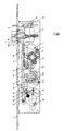
Gemäß Figur 4 ist der Zylinderbart 18 - und zwar ausgehend von der Stellung
nach Figur 3 - weiter in der Bildebene um etwa weitere 30° nach
rechts bewegt worden. Hierbei ist der um eine Schwenkachse 38 drehbare
Einschalthebel 14 verschwenkt worden und hat über einen Schaltnocken
32 das Wechselteil 12 in der Bildebene nach oben verschoben.
Gleichzeitig ist der Ausschalthebel 15 um seine Schwenkachse 39 in
rechtsdrehendem Sinne geringfügig verschwenkt worden. Das Anheben
des Wechselteils 12 hat zur Folge, daß ein Schaltnocken 33 des
Wechselteils 12 gegen eine entsprechende Kante eines Zwischenhebels
13 läuft und der Zwischenhebel 13 um die mit dem Schloßblech verbundene
Achse 41 schwenkt. Der Zwischenhebel 13 selbst schwenkt
dabei gegen einen um die an der Drückernuß 9 angeordnete Achse 43
schwenkbaren Umschalthebel 10, welcher die beiden Nußhälften miteinander
verriegelt. In dieser Situation kann der Riegel 6 von beiden
Türseiten über den jeweiligen Drücker betätigt werden. According to Figure 4, the cylinder bit 18 - and that starting from the position
according to Figure 3 - further in the image plane by about another 30 °
been moved to the right. Here, the one that is rotatable about a
Um das Wechselteil 12 in seiner Position zu halten, sind in einer Ausnehmung
34 im Wechselteil 12 durch eine Feder 36 getrennte Schaltkeile 16
vorgesehen, die mit fest mit dem Schloßblech verbundenen Führungsnokken
35 korrespondieren. Die Ausnehmung 34 im Wechselteil 12 ist durch
eine Abdeckfläche 37 eines Abdeckbleches 17 abdeckbar. im Wechselteil
12 sowie im Abdeckblech 17 sind ferner Ausnehmungen 44 vorgesehen,
die eine ausreichende Verschiebung der Achse 41 des Zwischenhebels
13 innerhalb dieser Ausnehmung zulassen.In order to hold the
In der Schlüsselposition gemäß Figur 4 ergibt sich die Besonderheit, daß
(vergleiche Figur 3) der Zylinderbart 18 gleichzeitig einen Betätigungsarm
46 des Einschalthebels 14 und den Anschlag 29 des Schiebers 5 abstützt.
Wird der Schlüssel in dieser Position belassen, ergibt sich eine sogenannte
"Dauerauf-Funktion", d.h., die Tür kann durch Aufstoßen oder
Aufziehen ohne Drückerbetätigung beliebig oft geöffnet und geschlossen
werden, ohne daß der Riegel 6 in die ihm zugeordnete Ausnehmung des
Schließbleches einfährt. Es erfolgt also kein Riegelausschluß. Die vorbeschriebene
Schlüsselstellung wird vorteilhaft dadurch fixiert, daß im Bereich
der Rotationskurve der Schließzylinderkontur 4 ein Begrenzungsnocken
42 angeordnet ist, der eine weitere Drehung des Schlüssels in
rechtsdrehendem Sinne verhindert.In the key position according to FIG. 4 there is the peculiarity that
(compare Figure 3) the
Bei einer Schlüsseldrehung in linksdrehendem Sinne - ausgehend von Figur 4 - ist die "Dauerauf-Funktion" aufgehoben; die Umschaltfunktion bleibt jedoch bestehen.With a key turn in the left-hand sense - starting from the figure 4 - the "continuous open" function is canceled; the toggle function remains however.
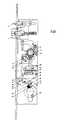
In der Darstellung gemäß Figur 5 ist - ausgehend von der Position nach
Figur 4 - der Schlüssel in linksdrehendem Sinne betätigt worden; dabei
schwenkt der Zylinderbart 18 den Ausschalthebel 15 in linksdrehendem
Sinne, so daß der Ausschalthebel 15 über einen Schaltnocken 32 am
Wechselteil 12 das Wechselteil 12 in der Bildebene nach unten verschiebt,
so daß sich die Schaltkeile 16 nunmehr im wesentlichen unterhalb
der Führungsnocken 35 befinden. Die Nußhälften sind somit entkoppelt.
Beim Schließen der Tür wird - wie vorbeschrieben - die durch
eine Feder 31 belastete Kreuzfalle 7 in das Schließblech einfahren, das
Absenken des Schiebers 5 freigeben, so daß der Riegel 6 verzögert in
das Schließblech einfahren kann.In the illustration according to FIG. 5 - starting from the position
Figure 4 - the key has been operated in a counterclockwise direction; there
the
In der Figur 6 sind mit 27 im Steuerschlitz 26 des Schiebers 5 angeordnete
Raststellen bezeichnet; diese Raststellen 27 verhindern ein
unerwünschtes Zurückdrücken des Schiebers 5 auch dann, wenn der
Schieber 5 nicht vollständig in die entsprechende Ausnehmung des
Schließbleches eingefahren, also nicht vollständig vorgeschlossen ist. In FIG. 6, 27 are arranged in the
- 11
- Panikschloßpanic lock
- 22
- Schloßblechlock plate
- 33
- Stulpstulp
- 44
- SchließzylinderkonturLocking cylinder contour
- 55
- Schieberpusher
- 66
- Riegelbars
- 77
- Kreuzfallecross case
- 88th
- Steuerteilcontrol part
- 99
- Drückernußspindle hole
- 1010
- UmschalthebelSwitching lever
- 1111
- Panikhebelpanic lever
- 11'11 '
- Panikhebelpanic lever
- 1212
- Wechselteilexchange part
- 1313
- Zwischenhebelintermediate lever
- 1414
- Einschalthebelcarriage handle
- 1515
- Ausschalthebeloff lever
- 1616
- Schaltkeileswitching wedges
- 1717
- AbdeckblechCover plate
- 1818
- Zylinderbartcylinder Bart
- 18'18 '
- Grundstellung des ZylinderbartesBasic position of the cylinder beard
- 1919
- KreuzfallenschaftCross latch shaft
- 2020
- Zapfen am KreuzfallenschaftCones on the cross drop shaft
- 2121
- Schlitz im SchieberSlit in the slider
- 2222
- Haltenocken am SteuerteilHolding cams on the control section
- 2323
- hakenartiger Fortsatz am Schieberhook-like extension on the slide
- 2424
- Riegelfortsatz des SteuerteilsBolt extension of the control section
- 2525
- Anschlagkante am SchieberStop edge on the slide
- 2626
- Steuerschlitz des SchiebersControl slit of the slide
- 2727
- Raststelle im SteuerschlitzRest area in the control slot
- 2828
- Dorn des RiegelsThorn of the bolt
- 2929
- Anschlag am RiegelStop on the bolt
- 3030
- Rückholfeder des RiegelsReturn spring of the bolt
- 3131
- Feder für KreuzfalleCross trap spring
- 3232
- Schaltnocken am Wechselteil Switch cams on the interchangeable part
- 3333
- Schaltnocken am WechselteilSwitch cams on the interchangeable part
- 3434
- Ausnehmung im WechselteilRecess in the interchangeable part
- 3535
- Führungsnocken für SchaltkeileGuide cams for switching wedges
- 3636
- Feder für SchaltkeileSpring for switching wedges
- 3737
- Abdeckfläche des AbdeckblechesCover surface of the cover plate
- 3838
- Schwenkachse für EinschalthebelSwivel axis for switch lever
- 3939
- Schwenkachse für AusschalthebelSwivel axis for switch-off lever
- 4040
- Anschlagnocken am WechselteilStop cam on the interchangeable part
- 4141
- Achse des ZwischenhebelsAxle of the intermediate lever
- 4242
- Begrenzungsnocken an der RotationskurveLimiting cams on the rotation curve
- 4343
- Achse des UmschalthebelsShift lever axis
- 4444
- Ausnehmung im WechselteilRecess in the interchangeable part
- 4444
- Ausnehmung im AbdeckblechRecess in the cover plate
- 4545
- Schieberkanteslide edge
- 4646
- Betätigungsarmactuating arm
Claims (8)
- A self-locking panic lock (1) comprising a spring loaded latch (7), a slide-controlled bolt (6), a slide (5) adapted to be actuated in the longitudinal direction of the lock by means of a key actuation, and a spring-loaded control part (8) which renders the slide (5) immobile when the bolt (6) is locked back, and comprising a divided handle boss (9), which has a panic lever (11) actuating the slide, the lock internal fittings presenting a displaceable changeover part (12) via which the boss halves may be optionally coupled and decoupled, and that the changeover part (12) being rendered immobile in its respective end position with regard to the lock plate (2) characterised in that the displaceable changeover part (12) can be rendered immobile through the actuation of the key in both longitudinal directions of the lock (1) when the bolt (6) is locked back, the changeover part (12) being rendered immobile in its respective end position via two actuating wedges (16), spaced apart by a spring in diametric arrangement, and being guided by force on the one hand in a recess (34) of the changeover part (12) and on the other hand on guiding cams (35) of the lock plate (2).
- A self-locking panic lock according to claim 1, characterised in that a cover plate (17) covering a recess (34) accommodating the actuation wedges (16) is disposed between the changeover part (12) and the slide (5).
- A self-locking panic lock according to claims 1 or 2, characterised in that the changeover part (12) is displaceable into its position in which it couples the boss halves, the displacement being effected by means of an engagement lever (14) pivotally mounted on the lock plate (2) and actuated by the key actuation.
- A self-locking panic lock according to claims 1 or 3, characterised in that the changeover part (12) is displaceable into its position in which it decouples the boss halves, the displacement being effected by means of a disengagement lever (15) pivotally mounted on the lock plate (2) and actuated by the key actuation.
- A self-locking panic lock according to claim 4, characterised in that the disengagement lever (15) is designed as a two-armed lever.
- A self-locking panic lock according to any one of claims 1 to 5, characterised in that a common cam (32) disposed on the changeover part (12) is associated with the engagement lever (14) and with the disengagement lever (15).
- A self-locking panic lock according to any one of claims 1 to 6, characterised in that the changeover part (12) is rendered immobile in its respective end position by actuating wedges (16) positively guided on the one hand in a recess (34) of the changeover part (12) and on the other hand on guide cams (35) of the lock plate (2).
- A self-locking panic lock according to any one of claims 1 to 7, characterised in that both the slide (5) and the engagement lever (14) displacing the changeover part (12) are adapted to be rendered immobile by the key actuation (lock cylinder ward 18) when the bolt (6) is locked back and the boss halves of the handle boss (9) are coupled (permanently open function).
Applications Claiming Priority (2)
| Application Number | Priority Date | Filing Date | Title |
|---|---|---|---|
| DE19620908 | 1996-05-24 | ||
| DE19620908A DE19620908C1 (en) | 1996-05-24 | 1996-05-24 | Self-locking emergency lock |
Publications (3)
| Publication Number | Publication Date |
|---|---|
| EP0808976A2 EP0808976A2 (en) | 1997-11-26 |
| EP0808976A3 EP0808976A3 (en) | 1999-02-10 |
| EP0808976B1 true EP0808976B1 (en) | 2003-04-16 |
Family
ID=7795190
Family Applications (1)
| Application Number | Title | Priority Date | Filing Date |
|---|---|---|---|
| EP97102645A Expired - Lifetime EP0808976B1 (en) | 1996-05-24 | 1997-02-19 | Self-locking emergency lock |
Country Status (3)
| Country | Link |
|---|---|
| EP (1) | EP0808976B1 (en) |
| AT (1) | ATE237724T1 (en) |
| DE (2) | DE19620908C1 (en) |
Families Citing this family (6)
| Publication number | Priority date | Publication date | Assignee | Title |
|---|---|---|---|---|
| DE19626745C1 (en) * | 1996-07-03 | 1997-10-16 | Dorma Gmbh & Co Kg | Self-securing panic door lock with spring-loaded cruciform latch |
| DE19748443A1 (en) * | 1997-11-03 | 1999-05-06 | Winkhaus Fa August | Espagnolette lock |
| DE20300394U1 (en) | 2003-01-10 | 2003-04-30 | Bks Gmbh, 42549 Velbert | mortise lock |
| DE102006001003A1 (en) * | 2006-01-05 | 2007-07-12 | Dorma Gmbh + Co. Kg | Electromechanical door lock |
| CN102137979A (en) * | 2008-08-05 | 2011-07-27 | 西莎股份公司 | Universal lock for sliding doors |
| CN102966277B (en) * | 2011-09-01 | 2014-11-12 | 松下电气机器(北京)有限公司 | Subway emergency door lock mechanism |
Family Cites Families (5)
| Publication number | Priority date | Publication date | Assignee | Title |
|---|---|---|---|---|
| DE3521213A1 (en) * | 1985-06-13 | 1986-12-18 | BKS GmbH, 5620 Velbert | LATCH PANIC LOCK, ESPECIALLY FOR PIPE FRAME |
| DE3636237A1 (en) * | 1986-10-24 | 1988-04-28 | Betz Gmbh & Co Kg Geb | Panic lock |
| DE3736592C2 (en) * | 1987-10-29 | 1994-02-17 | Kirchmann Niederdrenk Kg | Pipe frame lock |
| FI83802C (en) * | 1988-11-25 | 1991-08-26 | Abloy Security Ltd Oy | ELEKTROMEKANISKT DOERRLAOS. |
| ES2066673B1 (en) * | 1992-07-20 | 1996-10-16 | Talleres Escoriaza Sa | PERFECTED ANTI-PANIC LOCK. |
-
1996
- 1996-05-24 DE DE19620908A patent/DE19620908C1/en not_active Expired - Fee Related
-
1997
- 1997-02-19 DE DE59709818T patent/DE59709818D1/en not_active Expired - Lifetime
- 1997-02-19 AT AT97102645T patent/ATE237724T1/en not_active IP Right Cessation
- 1997-02-19 EP EP97102645A patent/EP0808976B1/en not_active Expired - Lifetime
Also Published As
| Publication number | Publication date |
|---|---|
| ATE237724T1 (en) | 2003-05-15 |
| DE59709818D1 (en) | 2003-05-22 |
| EP0808976A2 (en) | 1997-11-26 |
| EP0808976A3 (en) | 1999-02-10 |
| DE19620908C1 (en) | 1997-08-21 |
Similar Documents
| Publication | Publication Date | Title |
|---|---|---|
| EP1932989B1 (en) | Locking device for doors, windows or similar, in particular an espagnolette lock with panic function and multi-point locking | |
| EP0670404B1 (en) | Automatically releasing lock | |
| EP1932990A2 (en) | Locking device for doors, windows or similar, in particular an espagnolette lock with a panic function and multi-point locking | |
| EP1970507A2 (en) | Anti panic lock | |
| EP0816603B1 (en) | Self-locking antipanic lock | |
| EP0816602B1 (en) | Self-locking mortise lock | |
| EP0807736B1 (en) | Mortise lock | |
| EP1032743B1 (en) | Self-locking panic lock | |
| EP0466677A2 (en) | Fastener with several bolts | |
| EP0808976B1 (en) | Self-locking emergency lock | |
| EP2206858A1 (en) | Door lock | |
| DE19630972A1 (en) | Lock | |
| EP0143332B1 (en) | Quick release catch for a locked door | |
| DE19546466C1 (en) | Safety lock | |
| EP1683936B1 (en) | Lock with latch and latch drive | |
| DE19609484C2 (en) | Mortise lock | |
| EP0701037B1 (en) | Lock for prison doors | |
| EP0913550B2 (en) | Espagnolette lock | |
| DE102018119986A1 (en) | OPERATING GEARBOX FOR SLIDING A DRIVE ROD OF A WINDOW OR DOOR | |
| EP1617018B1 (en) | Electromechanical door lock | |
| DE10024305A1 (en) | Lock with latch and bolt | |
| EP1936076B1 (en) | Self-locking anti panic lock | |
| DE2361307A1 (en) | Multi tumbler emergency opening lock - ensures key can be withdrawn when outside handle is decoupled and moves freely | |
| EP1936074A2 (en) | Self-locking anti panic lock and method for operating a self-locking anti panic lock | |
| EP0790376B1 (en) | Espagnolette lock |
Legal Events
| Date | Code | Title | Description |
|---|---|---|---|
| PUAI | Public reference made under article 153(3) epc to a published international application that has entered the european phase |
Free format text: ORIGINAL CODE: 0009012 |
|
| AK | Designated contracting states |
Kind code of ref document: A2 Designated state(s): AT BE CH DE FI FR GB IT LI LU NL SE |
|
| ITCL | It: translation for ep claims filed |
Representative=s name: DE DOMINICIS & MAYER S.R.L. |
|
| GBC | Gb: translation of claims filed (gb section 78(7)/1977) | ||
| EL | Fr: translation of claims filed | ||
| TCNL | Nl: translation of patent claims filed | ||
| PUAL | Search report despatched |
Free format text: ORIGINAL CODE: 0009013 |
|
| AK | Designated contracting states |
Kind code of ref document: A3 Designated state(s): AT BE CH DE FI FR GB IT LI LU NL SE |
|
| 17P | Request for examination filed |
Effective date: 19990810 |
|
| 17Q | First examination report despatched |
Effective date: 20000518 |
|
| GRAH | Despatch of communication of intention to grant a patent |
Free format text: ORIGINAL CODE: EPIDOS IGRA |
|
| GRAH | Despatch of communication of intention to grant a patent |
Free format text: ORIGINAL CODE: EPIDOS IGRA |
|
| GRAA | (expected) grant |
Free format text: ORIGINAL CODE: 0009210 |
|
| AK | Designated contracting states |
Designated state(s): AT BE CH DE FI FR GB IT LI LU NL SE |
|
| REG | Reference to a national code |
Ref country code: GB Ref legal event code: FG4D Free format text: NOT ENGLISH |
|
| REG | Reference to a national code |
Ref country code: CH Ref legal event code: EP |
|
| REF | Corresponds to: |
Ref document number: 59709818 Country of ref document: DE Date of ref document: 20030522 Kind code of ref document: P |
|
| GBT | Gb: translation of ep patent filed (gb section 77(6)(a)/1977) | ||
| REG | Reference to a national code |
Ref country code: SE Ref legal event code: TRGR |
|
| ET | Fr: translation filed | ||
| PG25 | Lapsed in a contracting state [announced via postgrant information from national office to epo] |
Ref country code: AT Free format text: LAPSE BECAUSE OF NON-PAYMENT OF DUE FEES Effective date: 20040219 |
|
| PLBE | No opposition filed within time limit |
Free format text: ORIGINAL CODE: 0009261 |
|
| STAA | Information on the status of an ep patent application or granted ep patent |
Free format text: STATUS: NO OPPOSITION FILED WITHIN TIME LIMIT |
|
| PG25 | Lapsed in a contracting state [announced via postgrant information from national office to epo] |
Ref country code: LI Free format text: LAPSE BECAUSE OF NON-PAYMENT OF DUE FEES Effective date: 20040229 Ref country code: CH Free format text: LAPSE BECAUSE OF NON-PAYMENT OF DUE FEES Effective date: 20040229 |
|
| 26N | No opposition filed |
Effective date: 20040119 |
|
| REG | Reference to a national code |
Ref country code: CH Ref legal event code: PL |
|
| PGFP | Annual fee paid to national office [announced via postgrant information from national office to epo] |
Ref country code: IT Payment date: 20080223 Year of fee payment: 12 Ref country code: GB Payment date: 20080220 Year of fee payment: 12 Ref country code: FI Payment date: 20080215 Year of fee payment: 12 |
|
| PGFP | Annual fee paid to national office [announced via postgrant information from national office to epo] |
Ref country code: FR Payment date: 20080214 Year of fee payment: 12 |
|
| PGFP | Annual fee paid to national office [announced via postgrant information from national office to epo] |
Ref country code: LU Payment date: 20090303 Year of fee payment: 13 |
|
| PGFP | Annual fee paid to national office [announced via postgrant information from national office to epo] |
Ref country code: NL Payment date: 20090224 Year of fee payment: 13 |
|
| GBPC | Gb: european patent ceased through non-payment of renewal fee |
Effective date: 20090219 |
|
| PG25 | Lapsed in a contracting state [announced via postgrant information from national office to epo] |
Ref country code: FI Free format text: LAPSE BECAUSE OF NON-PAYMENT OF DUE FEES Effective date: 20090219 |
|
| REG | Reference to a national code |
Ref country code: FR Ref legal event code: ST Effective date: 20091030 |
|
| PG25 | Lapsed in a contracting state [announced via postgrant information from national office to epo] |
Ref country code: GB Free format text: LAPSE BECAUSE OF NON-PAYMENT OF DUE FEES Effective date: 20090219 Ref country code: FR Free format text: LAPSE BECAUSE OF NON-PAYMENT OF DUE FEES Effective date: 20090302 |
|
| REG | Reference to a national code |
Ref country code: NL Ref legal event code: V1 Effective date: 20100901 |
|
| PG25 | Lapsed in a contracting state [announced via postgrant information from national office to epo] |
Ref country code: NL Free format text: LAPSE BECAUSE OF NON-PAYMENT OF DUE FEES Effective date: 20100901 |
|
| PG25 | Lapsed in a contracting state [announced via postgrant information from national office to epo] |
Ref country code: IT Free format text: LAPSE BECAUSE OF NON-PAYMENT OF DUE FEES Effective date: 20090219 |
|
| PG25 | Lapsed in a contracting state [announced via postgrant information from national office to epo] |
Ref country code: LU Free format text: LAPSE BECAUSE OF NON-PAYMENT OF DUE FEES Effective date: 20100219 |
|
| PGFP | Annual fee paid to national office [announced via postgrant information from national office to epo] |
Ref country code: DE Payment date: 20130219 Year of fee payment: 17 Ref country code: SE Payment date: 20130219 Year of fee payment: 17 |
|
| PGFP | Annual fee paid to national office [announced via postgrant information from national office to epo] |
Ref country code: BE Payment date: 20130220 Year of fee payment: 17 |
|
| BERE | Be: lapsed |
Owner name: *DORMA G.M.B.H. + CO. K.G. Effective date: 20140228 |
|
| REG | Reference to a national code |
Ref country code: DE Ref legal event code: R119 Ref document number: 59709818 Country of ref document: DE |
|
| REG | Reference to a national code |
Ref country code: SE Ref legal event code: EUG |
|
| REG | Reference to a national code |
Ref country code: DE Ref legal event code: R119 Ref document number: 59709818 Country of ref document: DE Effective date: 20140902 |
|
| PG25 | Lapsed in a contracting state [announced via postgrant information from national office to epo] |
Ref country code: SE Free format text: LAPSE BECAUSE OF NON-PAYMENT OF DUE FEES Effective date: 20140220 |
|
| PG25 | Lapsed in a contracting state [announced via postgrant information from national office to epo] |
Ref country code: DE Free format text: LAPSE BECAUSE OF NON-PAYMENT OF DUE FEES Effective date: 20140902 Ref country code: BE Free format text: LAPSE BECAUSE OF NON-PAYMENT OF DUE FEES Effective date: 20140228 |