EP0808744B1 - Siège arrière de véhicule - Google Patents
Siège arrière de véhicule Download PDFInfo
- Publication number
- EP0808744B1 EP0808744B1 EP97108136A EP97108136A EP0808744B1 EP 0808744 B1 EP0808744 B1 EP 0808744B1 EP 97108136 A EP97108136 A EP 97108136A EP 97108136 A EP97108136 A EP 97108136A EP 0808744 B1 EP0808744 B1 EP 0808744B1
- Authority
- EP
- European Patent Office
- Prior art keywords
- cushion
- link
- seat
- floor
- seat back
- Prior art date
- Legal status (The legal status is an assumption and is not a legal conclusion. Google has not performed a legal analysis and makes no representation as to the accuracy of the status listed.)
- Expired - Lifetime
Links
- 230000003319 supportive effect Effects 0.000 claims description 15
- 238000010276 construction Methods 0.000 description 4
- 230000003014 reinforcing effect Effects 0.000 description 3
- 230000005540 biological transmission Effects 0.000 description 1
- 238000009434 installation Methods 0.000 description 1
- 238000012986 modification Methods 0.000 description 1
- 230000004048 modification Effects 0.000 description 1
Images


Classifications
-
- B—PERFORMING OPERATIONS; TRANSPORTING
- B60—VEHICLES IN GENERAL
- B60N—SEATS SPECIALLY ADAPTED FOR VEHICLES; VEHICLE PASSENGER ACCOMMODATION NOT OTHERWISE PROVIDED FOR
- B60N2/00—Seats specially adapted for vehicles; Arrangement or mounting of seats in vehicles
- B60N2/24—Seats specially adapted for vehicles; Arrangement or mounting of seats in vehicles for particular purposes or particular vehicles
- B60N2/30—Non-dismountable or dismountable seats storable in a non-use position, e.g. foldable spare seats
- B60N2/3088—Non-dismountable or dismountable seats storable in a non-use position, e.g. foldable spare seats characterised by the mechanical link
- B60N2/309—Non-dismountable or dismountable seats storable in a non-use position, e.g. foldable spare seats characterised by the mechanical link rods
-
- B—PERFORMING OPERATIONS; TRANSPORTING
- B60—VEHICLES IN GENERAL
- B60N—SEATS SPECIALLY ADAPTED FOR VEHICLES; VEHICLE PASSENGER ACCOMMODATION NOT OTHERWISE PROVIDED FOR
- B60N2/00—Seats specially adapted for vehicles; Arrangement or mounting of seats in vehicles
- B60N2/24—Seats specially adapted for vehicles; Arrangement or mounting of seats in vehicles for particular purposes or particular vehicles
- B60N2/30—Non-dismountable or dismountable seats storable in a non-use position, e.g. foldable spare seats
- B60N2/3002—Non-dismountable or dismountable seats storable in a non-use position, e.g. foldable spare seats back-rest movements
- B60N2/3004—Non-dismountable or dismountable seats storable in a non-use position, e.g. foldable spare seats back-rest movements by rotation only
- B60N2/3009—Non-dismountable or dismountable seats storable in a non-use position, e.g. foldable spare seats back-rest movements by rotation only about transversal axis
- B60N2/3013—Non-dismountable or dismountable seats storable in a non-use position, e.g. foldable spare seats back-rest movements by rotation only about transversal axis the back-rest being hinged on the vehicle frame
-
- B—PERFORMING OPERATIONS; TRANSPORTING
- B60—VEHICLES IN GENERAL
- B60N—SEATS SPECIALLY ADAPTED FOR VEHICLES; VEHICLE PASSENGER ACCOMMODATION NOT OTHERWISE PROVIDED FOR
- B60N2/00—Seats specially adapted for vehicles; Arrangement or mounting of seats in vehicles
- B60N2/24—Seats specially adapted for vehicles; Arrangement or mounting of seats in vehicles for particular purposes or particular vehicles
- B60N2/30—Non-dismountable or dismountable seats storable in a non-use position, e.g. foldable spare seats
- B60N2/3038—Cushion movements
- B60N2/304—Cushion movements by rotation only
- B60N2/3045—Cushion movements by rotation only about transversal axis
- B60N2/305—Cushion movements by rotation only about transversal axis the cushion being hinged on the vehicle frame
-
- B—PERFORMING OPERATIONS; TRANSPORTING
- B60—VEHICLES IN GENERAL
- B60N—SEATS SPECIALLY ADAPTED FOR VEHICLES; VEHICLE PASSENGER ACCOMMODATION NOT OTHERWISE PROVIDED FOR
- B60N2205/00—General mechanical or structural details
- B60N2205/30—Seat or seat parts characterised by comprising plural parts or pieces
- B60N2205/35—Seat, bench or back-rests being split laterally in two or more parts
Definitions
- the present invention relates to a vehicular rear seat of the type including a seat back provided at a rear portion of a seat cushion supported on an elevated step portion of a stepped floor in such a fashion that the seat back is capable of being stood up and laid down.
- the reverse surface of the seat back can be used as a luggage supportive floor surface.
- a seat back is provided at a rear portion of a seat cushion supported on an elevated step portion of a stepped floor such that the seat back is capable of being stood up and laid down, and in which when the seat cushion is swung up with a front portion thereof facing down and the seat back is laid down forward, the reverse surface of the seat back can be used as a luggage supportive floor surface, for example, as disclosed in Japanese Patent Laid-Open No. Hei 3-189245.
- this type of conventional vehicular rear seat has problems as follows. For example, when the seat cushion is swung up with the front portion thereof facing down, a space is left between the seat cushion and the front wall surface of the elevated step portion of the floor so that the seat cushion is not firmly maintained in a precise upstanding portion. If quick or panic braking is applied or the vehicle receives an impact from the forward direction so that a luggage piece moves forward on the luggage supportive floor surface, then the luggage piece, if it is small, may fall into the space and, if it is large, may apply a large load to a front seat via the seat cushion held in the upstanding state, thus impeding driving. To eliminate such problems, it becomes necessary to provide reinforcing members, such as a belt, a link or the like, for fixing the seat cushion in the upstanding state, thus causing another problem of structure complication.
- reinforcing members such as a belt, a link or the like
- an object of the present invention to provide a vehicular rear seat wherein when a seat back provided at a rear portion of a seat cushion is laid down forward to use the rear surface of the seat back as a luggage supportive floor surface, an upstanding seat cushion member reliably receives and stops a luggage piece placed on the luggage supportive floor surface if the luggage piece moves forward for any reason, thereby eliminating the danger of transmitting a large load to a front seat and the danger that the luggage piece will fall in the front of the luggage supportive floor surface even if it is a small piece and, further, no additional reinforcing member is required for retaining the seat cushion in a stable upstanding state, thus allowing simple structure design and low-cost production.
- a vehicular rear seat including a seat back provided at a rear portion of a seat cushion supported on an elevated step portion of a stepped floor such that the seat back is capable of assuming a raised position and a lowered position in which a reverse surface of the seat back becomes a luggage supportive floor surface.
- a lower cushion is supported on an upper surface of the elevated step portion.
- the seat cushion comprises an upper cushion capable of being laid on the lower cushion, and a link-type connection mechanism changeable between a normal state where the upper cushion is supported on the lower cushion and an upstanding state where the upper cushion is swung up with a front portion thereof facing down and where a reverse surface of the upper cushion abuts against and is supported on a front wall surface of the elevated step portion of the stepped floor.
- the link-type connection mechanism may comprise a first link connected at an end thereof to the stepped floor and a second link connected at an end thereof to the other end of the first link, the other end of the second link being connected to a seat frame.
- the upper cushion When the seat back has been laid down forward to use its reverse surface as a luggage supportive floor surface, the upper cushion will reliably receive and stop a luggage piece and prevent transmission of a large load to the front seat if the luggage piece moves forward on the luggage supportive floor surface.
- the rear seat of the present invention also substantially eliminates the danger that a luggage piece will fall into a space in front of the floor supportive floor surface even if it is a small piece. Moreover, since the rear seat requires no additional reinforcing member for stably holding the seat cushion in the upstanding state, the construction can be simplified and the production cost can be reduced.
- each of the seat back and the seat cushion of a vehicular rear seat is divided into two parts in width at 6:4, i.e., a 60%-40% split.
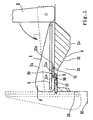
- a seat cushion 1 is supported on an elevated step portion 21 of a stepped floor 20, and a seat back 2 is provided at a rear portion of the seat cushion 1 in such a manner that the seat back 2 is capable of being moved between raised and lowered positions.
- Each of the seat cushion 1 and the seat back 2 comprises a wide part and a narrow part (divided in width at 6:4) disposed side by side as shown in Fig. 3.
- the description below will be mainly made in conjunction with the wide parts since the wide and narrow parts have substantially the same construction, with the exception of width.
- the reverse surface of the seat back 2 can be used as a luggage supportive floor surface.
- the basic structure thereof is substantially the same as that of a seat back according to the conventional art.
- the seat cushion 1 is comprised of an upper cushion 1b and is laid over a lower cushion 1a supported on an upper surface of the elevated step portion 21 of the floor 20.
- the reverse surface of the upper cushion 1b and the lower cushion 1a are covered with the same carpet material as used for the floor.
- recesses 4 are formed on the elevated step portion 21 of the stepped floor 20 corresponding to connection mechanism mounting protrusions 23 extending in the fore-to-aft direction near opposite side ends of a front half portion of the elevated step portion 21.
- Portions of the lower cushion 1a corresponding to the connection mechanism mounting protrusions 23 have reduced thicknesses.
- Each thin portion of the lower cushion 1a has a connection mechanism mounting cutout 3 extending in the fore-to-aft direction to the front edge of the lower cushion 1a, which substantially coincides with the front edge of the elevated step portion 21.
- Reference numeral 10 represents a link-type connection mechanism that connects the upper cushion 1b to the elevated step portion 21Of thesteppediloor20.
- the link-type connection mechanism 10 enables changing between two states, that is, a normal state where the lower surface of the upper cushion 1b is supported on the upper surface of the lower cushion 1a, and an upstanding state where the upper cushion 1b is swung up with its front portion facing down and the reverse face of the front portion of the upper cushion 1b abuts against and is supported on a front wall surface 22 of the elevated step portion 21 of the stepped floor 20.
- the link-type connection mechanism 10 comprises brackets 12 each fixed to a top portion of the corresponding protrusion 23 by stud bolts 13, first links 11a, each of which is rotatably connected at an end thereof to the corresponding bracket 12, and second links 11b, each of which is rotatably connected at an end thereof to the other end of the corresponding first link 11a.
- the other end of each second link 11b is connected to a lever 15 rotatably supported to mounting plates 14 provided on a seat frame 5 by a bracket 12b, as shown in Fig. 2.
- connection mechanism 10 is constructed so that when the upper cushion 1b is turned into the upstanding state, the pairs of first link 11a and the second link 11b are received in the corresponding cutouts 3 formed in the front portion of the lower cushion 1a while extending linearly along a floor surface. Thereby, the operability and stability at the time of swinging up the upper cushion 1b are improved. Stoppers 16 that restrict the upper cushion 1b to a predetermined position when the upper cushion 1b is in the normal state, where the upper cushion 1b is supported on the lower cushion 1a with the lower surface of the upper cushion 1b facing the upper surface of the lower cushion 1a.
- the rear seat is normally used in the normal state, as indicated by solid lines in Fig. 1, where the lower face of the upper cushion 1b is supported on the upper face of the lower cushion 1a, and when necessary, the upper cushion 1b is swung up with a front portion thereof facing down and the seat back 2 is laid down forward so that the reverse side of the seat back 2 may be used as a luggage supportive floor surface.
- the upper cushion 1b is held in the upstanding state with the reverse face of the front portion of the upper cushion 1b abutting against and being supported on the front wall surface of the elevated step portion 21 of the stepped floor 20, and the upstanding state of the upper cushion 1b can be stably maintained. Therefore, if a luggage piece on the luggage supportive floor surface moves forward and hits the upstanding upper cushion 1b, the upper cushion 1b is reliably prevented from moving forward and giving an impact to the front seat.
- the embodiment eliminates an incident that a luggage piece falls through such a space if it is a small piece.
- the embodiment employs only a simple mechanism, that is, the link-type connection mechanism, without additional mechanism, the embodiment achieves an installation space reduction and a cost reduction.
Landscapes
- Engineering & Computer Science (AREA)
- Aviation & Aerospace Engineering (AREA)
- Transportation (AREA)
- Mechanical Engineering (AREA)
- Seats For Vehicles (AREA)
Claims (3)
- Siège arrière de véhicule comprenant :caractérisé en ce queun dossier de siège (2) pourvu en une partie arrière d'un coussin de siège (1), ledit coussin étant soutenu sur une surface supérieure d'une partie étagée surélevée (21) d'un plancher étagé (20) de sorte que le dossier de siège (2) peut se placer dans une position surélevée et dans une position abaissée dans laquelle une face verso du dossier de siège devient une surface de plancher porte-bagages ; etun mécanisme de liaison du type tringle (10) modifiable entre un état normal dudit coussin (1) dans lequel le coussin (1) est soutenu sur la partie étagée surélevée (21) et un état vertical du coussin (1) dans lequel la face verso d'une partie frontale du coussin (1) aboute et entre en contact contre une surface de paroi frontale (22) de la partie étagée surélevée (21) du plancher étagé (20) ;
ledit dossier de siège (2) peut être couché vers l'avant, de sorte que son côté verso peut être utilisé comme surface de plancher porte-bagages, seulement après que ledit coussin (1) aura pivoté et se sera placé dans son état vertical ; et
ledit mécanisme de liaison du type tringle (10) est relié par son côté coussin (15) audit coussin (1) de sorte que, dans la position normale dudit coussin (1), ledit côté coussin (15) se trouve séparé dudit bord frontal dudit coussin (1) dans le sens de l'avant vers l'arrière. - Siège arrière de véhicule selon la revendication 1, dans lequel un coussin inférieur (1a) est soutenu sur ladite surface supérieure de ladite partie étagée surélevée (21) et dans lequel ledit coussin de siège (1) comprend un coussin supérieur (1b) pouvant être couché sur le coussin inférieur (1a), ledit mécanisme de liaison du type tringle (10) étant en liaison avec ledit coussin supérieur (1b).
- Siège arrière de véhicule selon la revendication 1 ou 2, dans lequel le mécanisme de liaison du type tringle (10) comprend une première tringle (11a) reliée en une extrémité de celle-ci au plancher étagé (20) et une seconde tringle (11b) reliée en une extrémité de celle-ci à l'autre extrémité de 1a première tringle (11a), l'autre extrémité de la seconde tringle (11b) constituant ladite extrémité du côté coussin (15) étant reliée à une armature de siège (5), et dans lequel, lorsque le coussin (1) ou le coussin supérieur (1b) est dans l'état d'érection verticale, ladite première tringle (11a) et ladite seconde tringle (11b) sont reçues dans une découpe (3) formée dans le coussin inférieur (1a), de telle façon que ladite première tringle (11a) et ladite seconde tringle (11b) deviennent sensiblement linéaires le long d'une surface de plancher de ladite partie étagée surélevée (21).
Applications Claiming Priority (3)
| Application Number | Priority Date | Filing Date | Title |
|---|---|---|---|
| JP125798/96 | 1996-05-21 | ||
| JP12579896A JP3413326B2 (ja) | 1996-05-21 | 1996-05-21 | 車輌用リヤシート |
| JP12579896 | 1996-05-21 |
Publications (3)
| Publication Number | Publication Date |
|---|---|
| EP0808744A2 EP0808744A2 (fr) | 1997-11-26 |
| EP0808744A3 EP0808744A3 (fr) | 1999-01-07 |
| EP0808744B1 true EP0808744B1 (fr) | 2005-10-19 |
Family
ID=14919164
Family Applications (1)
| Application Number | Title | Priority Date | Filing Date |
|---|---|---|---|
| EP97108136A Expired - Lifetime EP0808744B1 (fr) | 1996-05-21 | 1997-05-20 | Siège arrière de véhicule |
Country Status (4)
| Country | Link |
|---|---|
| US (1) | US5988726A (fr) |
| EP (1) | EP0808744B1 (fr) |
| JP (1) | JP3413326B2 (fr) |
| DE (1) | DE69734372T2 (fr) |
Cited By (1)
| Publication number | Priority date | Publication date | Assignee | Title |
|---|---|---|---|---|
| FR3152147A1 (fr) * | 2023-08-17 | 2025-02-21 | Safran Seats | Organe de préhension pour coussins d'un siège multiplace |
Families Citing this family (11)
| Publication number | Priority date | Publication date | Assignee | Title |
|---|---|---|---|---|
| DE19837838C1 (de) * | 1998-08-20 | 1999-11-18 | Daimler Chrysler Ag | Rücksitzanordnung für Fahrgastzellen |
| US6293603B1 (en) * | 1998-10-05 | 2001-09-25 | Honda Giken Kogyo Kabushiki Kaisha | Vehicular seat |
| GB2356557B (en) * | 1999-11-26 | 2003-12-17 | Autoliv Dev | Improvements in or relating to a vehicle seat unit |
| FR2860458B1 (fr) * | 2003-10-02 | 2006-12-01 | Renault Sa | Siege transformable pour vehicule automobile |
| US6925351B2 (en) * | 2003-11-19 | 2005-08-02 | Action Tapes, Inc. | Method and system for updating stitch data in a memory card via a wireless transmission |
| FR2868997B1 (fr) * | 2004-04-15 | 2006-06-09 | Renault Sas | Siege arriere de vehicule automobile pourvu d'une cuvette anti-sousmarinage escamotable, et vehicule correspondant |
| KR100568980B1 (ko) * | 2004-04-26 | 2006-04-07 | 기아자동차주식회사 | 차량의 시트 폴딩 장치 |
| DE102005030032A1 (de) * | 2005-06-27 | 2007-01-04 | Johnson Controls Gmbh | Fahrzeugsitz mit Gebrauchs- und Ladestellung |
| DE202010002237U1 (de) * | 2009-03-19 | 2010-07-08 | Keiper Gmbh & Co. Kg | Fahrzeugsitz, insbesondere Kraftfahrzeugsitz |
| US9744882B2 (en) | 2015-12-04 | 2017-08-29 | Honda Motor Co., Ltd. | Two-axis seat hinge |
| GB2593720B (en) * | 2020-03-31 | 2022-03-23 | Mcmurtry Automotive Ltd | Vehicle seat |
Family Cites Families (18)
| Publication number | Priority date | Publication date | Assignee | Title |
|---|---|---|---|---|
| US2152505A (en) * | 1935-05-01 | 1939-03-28 | Gen Motors Corp | Reversible seat and squab |
| FR1499448A (fr) * | 1966-09-16 | 1967-10-27 | Renault | Siège arrière de véhicule |
| IT1117302B (it) * | 1976-06-03 | 1986-02-17 | Citroen Sa | Autoveicolo con sedile ribaltabile |
| US4133556A (en) * | 1977-07-18 | 1979-01-09 | General Motors Corporation | Seat belt positioning device |
| JPS57205239A (en) * | 1981-06-11 | 1982-12-16 | Mazda Motor Corp | Rear seat of automobile |
| SE8202022L (sv) * | 1982-03-30 | 1983-10-01 | Saab Scania Ab | Anordning for omstellning av fordonsseten |
| JPS61113138U (fr) * | 1984-12-28 | 1986-07-17 | ||
| JPH03125625A (ja) * | 1989-10-09 | 1991-05-29 | Toyota Autom Loom Works Ltd | 車両用ガラス窓 |
| SE464071B (sv) * | 1989-12-12 | 1991-03-04 | Saab Automobile | Arrangemang vid passagerarsaete i fordon |
| US5133589A (en) * | 1990-03-13 | 1992-07-28 | Tachi-S Co., Ltd. | Pivoting seat and pivoting backrest having cooperating latch means |
| IT1246075B (it) * | 1991-05-28 | 1994-11-07 | Sepi Spa | Dispositivo a doppia articolazione per lo schienale abbattibile di un sedile posteriore di autoveicolo e sedile di autoveicolo comprendentetale dispositivo. |
| JP3131253B2 (ja) * | 1991-09-30 | 2001-01-31 | 日産自動車株式会社 | シート支持装置 |
| JP3400066B2 (ja) * | 1993-03-30 | 2003-04-28 | マツダ株式会社 | 自動車のシートスライド装置 |
| US5702145A (en) * | 1994-06-29 | 1997-12-30 | Lear Seating Corporation | Folding second seat with seat track release latch mechanism |
| US5558386A (en) * | 1995-04-20 | 1996-09-24 | Chrysler Corporation | Asymmetrical wire hook latch arrangement |
| JP3036408B2 (ja) * | 1995-09-22 | 2000-04-24 | トヨタ自動車株式会社 | 車両用リヤシート装置 |
| US5658046A (en) * | 1996-01-16 | 1997-08-19 | Lear Corporation | Vehicle seat trim cover attachment strip |
| US5641202A (en) * | 1996-01-16 | 1997-06-24 | Lear Seating Corporation | Release latch for utility seat |
-
1996
- 1996-05-21 JP JP12579896A patent/JP3413326B2/ja not_active Expired - Fee Related
-
1997
- 1997-05-16 US US08/857,479 patent/US5988726A/en not_active Expired - Lifetime
- 1997-05-20 EP EP97108136A patent/EP0808744B1/fr not_active Expired - Lifetime
- 1997-05-20 DE DE69734372T patent/DE69734372T2/de not_active Expired - Lifetime
Cited By (1)
| Publication number | Priority date | Publication date | Assignee | Title |
|---|---|---|---|---|
| FR3152147A1 (fr) * | 2023-08-17 | 2025-02-21 | Safran Seats | Organe de préhension pour coussins d'un siège multiplace |
Also Published As
| Publication number | Publication date |
|---|---|
| JPH09301030A (ja) | 1997-11-25 |
| DE69734372D1 (de) | 2005-11-24 |
| DE69734372T2 (de) | 2006-07-27 |
| EP0808744A2 (fr) | 1997-11-26 |
| US5988726A (en) | 1999-11-23 |
| JP3413326B2 (ja) | 2003-06-03 |
| EP0808744A3 (fr) | 1999-01-07 |
Similar Documents
| Publication | Publication Date | Title |
|---|---|---|
| EP0808744B1 (fr) | Siège arrière de véhicule | |
| US5265937A (en) | Seat back inertia lock | |
| US4146267A (en) | Adjusting device for reclining seat | |
| US6543831B2 (en) | Windshield mounting structure for vehicles | |
| US6003716A (en) | Dual opening console | |
| JPS6144485B2 (fr) | ||
| US5383532A (en) | Foot pedal locking device for cargo-handling vehicle | |
| US4707010A (en) | Inertial latching mechanism for seat assemblies | |
| US20020125757A1 (en) | Vehicle seat provided with a fold-down back | |
| JPS6253377B2 (fr) | ||
| WO2001096141A1 (fr) | Verrouillage a inertie sensible pour vehicule | |
| US5611600A (en) | Catch hook for the releasable locking of the backrest connected with the seat part of a vehicle seat such that the backrest can swivel forward | |
| EP1132252B1 (fr) | Glissière pour siège de véhicule | |
| EP0769411B1 (fr) | Siège arrière pour véhicules | |
| GB2207860A (en) | Vehicle seats | |
| JP2001239861A (ja) | シートスライド装置 | |
| CA2130497C (fr) | Dispositif de verrouillage reglable a l'infini pour appareil monte sur rail | |
| US5150871A (en) | Vehicle seat | |
| EP0580315B1 (fr) | Dispositif de verrouillage pour siège | |
| EP0269348B1 (fr) | Appareil de commande d'inclinaison | |
| JPH0435228Y2 (fr) | ||
| KR0153191B1 (ko) | 차량의 브레이크 페달 오작동 방지기구 | |
| JP3462117B2 (ja) | シートスライド装置のロック構造 | |
| JP2717976B2 (ja) | シートのスライド装置 | |
| EP0770513B1 (fr) | Dispositif de verrouillage de glissières ajustables infiniment |
Legal Events
| Date | Code | Title | Description |
|---|---|---|---|
| PUAI | Public reference made under article 153(3) epc to a published international application that has entered the european phase |
Free format text: ORIGINAL CODE: 0009012 |
|
| 17P | Request for examination filed |
Effective date: 19970616 |
|
| AK | Designated contracting states |
Kind code of ref document: A2 Designated state(s): DE FR GB |
|
| PUAL | Search report despatched |
Free format text: ORIGINAL CODE: 0009013 |
|
| AK | Designated contracting states |
Kind code of ref document: A3 Designated state(s): DE FR GB |
|
| 17Q | First examination report despatched |
Effective date: 20010702 |
|
| GRAP | Despatch of communication of intention to grant a patent |
Free format text: ORIGINAL CODE: EPIDOSNIGR1 |
|
| RTI1 | Title (correction) |
Free format text: VEHICULAR REAR SEAT |
|
| GRAS | Grant fee paid |
Free format text: ORIGINAL CODE: EPIDOSNIGR3 |
|
| GRAA | (expected) grant |
Free format text: ORIGINAL CODE: 0009210 |
|
| RAP1 | Party data changed (applicant data changed or rights of an application transferred) |
Owner name: NHK SPRING CO.LTD. Owner name: TOYOTA JIDOSHA KABUSHIKI KAISHA Owner name: TAKASHIMAYA NIPPATSU KOGYO CO. LTD. |
|
| AK | Designated contracting states |
Kind code of ref document: B1 Designated state(s): DE FR GB |
|
| REG | Reference to a national code |
Ref country code: GB Ref legal event code: FG4D |
|
| RIN1 | Information on inventor provided before grant (corrected) |
Inventor name: MATSUFUJI, YORISUKE Inventor name: HASHIMOTO, KAZUNORI Inventor name: ONODA, KEISUKE |
|
| REF | Corresponds to: |
Ref document number: 69734372 Country of ref document: DE Date of ref document: 20051124 Kind code of ref document: P |
|
| ET | Fr: translation filed | ||
| PLBE | No opposition filed within time limit |
Free format text: ORIGINAL CODE: 0009261 |
|
| STAA | Information on the status of an ep patent application or granted ep patent |
Free format text: STATUS: NO OPPOSITION FILED WITHIN TIME LIMIT |
|
| 26N | No opposition filed |
Effective date: 20060720 |
|
| REG | Reference to a national code |
Ref country code: FR Ref legal event code: PLFP Year of fee payment: 20 |
|
| PGFP | Annual fee paid to national office [announced via postgrant information from national office to epo] |
Ref country code: GB Payment date: 20160518 Year of fee payment: 20 Ref country code: DE Payment date: 20160518 Year of fee payment: 20 |
|
| PGFP | Annual fee paid to national office [announced via postgrant information from national office to epo] |
Ref country code: FR Payment date: 20160412 Year of fee payment: 20 |
|
| REG | Reference to a national code |
Ref country code: DE Ref legal event code: R071 Ref document number: 69734372 Country of ref document: DE |
|
| REG | Reference to a national code |
Ref country code: GB Ref legal event code: PE20 Expiry date: 20170519 |
|
| PG25 | Lapsed in a contracting state [announced via postgrant information from national office to epo] |
Ref country code: GB Free format text: LAPSE BECAUSE OF EXPIRATION OF PROTECTION Effective date: 20170519 |