EP0808701B1 - Drahtsäge - Google Patents
Drahtsäge Download PDFInfo
- Publication number
- EP0808701B1 EP0808701B1 EP97107978A EP97107978A EP0808701B1 EP 0808701 B1 EP0808701 B1 EP 0808701B1 EP 97107978 A EP97107978 A EP 97107978A EP 97107978 A EP97107978 A EP 97107978A EP 0808701 B1 EP0808701 B1 EP 0808701B1
- Authority
- EP
- European Patent Office
- Prior art keywords
- wires
- fixed
- web
- wire
- support table
- Prior art date
- Legal status (The legal status is an assumption and is not a legal conclusion. Google has not performed a legal analysis and makes no representation as to the accuracy of the status listed.)
- Expired - Lifetime
Links
- 230000007246 mechanism Effects 0.000 claims description 10
- 230000003287 optical effect Effects 0.000 claims description 8
- 238000006073 displacement reaction Methods 0.000 claims description 6
- 238000009434 installation Methods 0.000 description 4
- 238000004519 manufacturing process Methods 0.000 description 3
- 239000003795 chemical substances by application Substances 0.000 description 2
- 239000013078 crystal Substances 0.000 description 2
- 230000010354 integration Effects 0.000 description 2
- 229910000639 Spring steel Inorganic materials 0.000 description 1
- PNEYBMLMFCGWSK-UHFFFAOYSA-N aluminium oxide Inorganic materials [O-2].[O-2].[O-2].[Al+3].[Al+3] PNEYBMLMFCGWSK-UHFFFAOYSA-N 0.000 description 1
- 229910010293 ceramic material Inorganic materials 0.000 description 1
- 239000013065 commercial product Substances 0.000 description 1
- 150000001875 compounds Chemical class 0.000 description 1
- 238000010276 construction Methods 0.000 description 1
- 238000012937 correction Methods 0.000 description 1
- 230000001419 dependent effect Effects 0.000 description 1
- 229910003460 diamond Inorganic materials 0.000 description 1
- 239000010432 diamond Substances 0.000 description 1
- 229910052733 gallium Inorganic materials 0.000 description 1
- 238000003780 insertion Methods 0.000 description 1
- 230000037431 insertion Effects 0.000 description 1
- 239000000463 material Substances 0.000 description 1
- 238000000034 method Methods 0.000 description 1
- 230000000284 resting effect Effects 0.000 description 1
- 229910052710 silicon Inorganic materials 0.000 description 1
- 239000010703 silicon Substances 0.000 description 1
- HBMJWWWQQXIZIP-UHFFFAOYSA-N silicon carbide Chemical compound [Si+]#[C-] HBMJWWWQQXIZIP-UHFFFAOYSA-N 0.000 description 1
- 229910010271 silicon carbide Inorganic materials 0.000 description 1
- 230000008685 targeting Effects 0.000 description 1
Images


Classifications
-
- B—PERFORMING OPERATIONS; TRANSPORTING
- B28—WORKING CEMENT, CLAY, OR STONE
- B28D—WORKING STONE OR STONE-LIKE MATERIALS
- B28D5/00—Fine working of gems, jewels, crystals, e.g. of semiconductor material; apparatus or devices therefor
- B28D5/0058—Accessories specially adapted for use with machines for fine working of gems, jewels, crystals, e.g. of semiconductor material
- B28D5/0082—Accessories specially adapted for use with machines for fine working of gems, jewels, crystals, e.g. of semiconductor material for supporting, holding, feeding, conveying or discharging work
- B28D5/0088—Accessories specially adapted for use with machines for fine working of gems, jewels, crystals, e.g. of semiconductor material for supporting, holding, feeding, conveying or discharging work the supporting or holding device being angularly adjustable
-
- B—PERFORMING OPERATIONS; TRANSPORTING
- B23—MACHINE TOOLS; METAL-WORKING NOT OTHERWISE PROVIDED FOR
- B23D—PLANING; SLOTTING; SHEARING; BROACHING; SAWING; FILING; SCRAPING; LIKE OPERATIONS FOR WORKING METAL BY REMOVING MATERIAL, NOT OTHERWISE PROVIDED FOR
- B23D57/00—Sawing machines or sawing devices not covered by one of the preceding groups B23D45/00 - B23D55/00
- B23D57/003—Sawing machines or sawing devices working with saw wires, characterised only by constructional features of particular parts
- B23D57/0053—Sawing machines or sawing devices working with saw wires, characterised only by constructional features of particular parts of drives for saw wires; of wheel mountings; of wheels
-
- B—PERFORMING OPERATIONS; TRANSPORTING
- B23—MACHINE TOOLS; METAL-WORKING NOT OTHERWISE PROVIDED FOR
- B23D—PLANING; SLOTTING; SHEARING; BROACHING; SAWING; FILING; SCRAPING; LIKE OPERATIONS FOR WORKING METAL BY REMOVING MATERIAL, NOT OTHERWISE PROVIDED FOR
- B23D57/00—Sawing machines or sawing devices not covered by one of the preceding groups B23D45/00 - B23D55/00
- B23D57/003—Sawing machines or sawing devices working with saw wires, characterised only by constructional features of particular parts
- B23D57/0061—Sawing machines or sawing devices working with saw wires, characterised only by constructional features of particular parts of devices for guiding or feeding saw wires
Definitions
- the present invention relates to a device for wire sawing comprising a sheet of wire stretched between at least two wire guide cylinders and held in position by grooves cut on the surface of said cylinders wire guides which define the interval between son of said layer of son, the son being susceptible to move in an alternating or continuous movement while support against a workpiece fixed on a support table.
- the sawing area is consisting of a set of cylinders placed in parallel. These cylinders, called wire guides, are engraved with grooves defining the interval between the wires of the tablecloth, the thickness of the slices.
- the workpiece is fixed on a support table which moves perpendicularly to the layer of wires. Travel speed defines the cutting speed.
- the renewal of the thread, as well as the control of its tension is done in a part called the wire management area outside the sawing area proper.
- the agent who will govern the cutting is either an abrasive attached to the wire, or an abrasive free brought in slip form.
- the wire only acts as a transporter.
- the tensioned wire is both guided and pulled by the thread guide cylinders.
- These generally coated cylinders of a synthetic layer are engraved with grooves including the geometry and dimensions must be of great precision.
- the direction of sawing is of great importance, so also the direction of the wire with respect to the single crystal himself and consequently compared to the table support of the workpiece.
- a device for adjusting the support table by relation to the son of the tablecloth is generally planned and carried out in the form of a rotating turntable placed between the machine and the support table. The support table then becomes rotary table.
- the object of the present invention is to remedy these disadvantages and it is characterized for this purpose by the sawing device includes means for angularly orient the sheet of wires with respect to the angularly fixed support table and to give said ply of wires a rotation function with respect to the support table, therefore relative to the workpiece.
- the height and size of the sawing device can be reduced. Transport and installation of the device are facilitated. The manufacturing price and the number of pieces can be kept low while getting a whole more easy to use, more rigid and therefore more robust.
- Case 1 corresponds to known devices.
- the case 3) has no advantage because it combines the disadvantages of the first two methods.
- case 2 by aligning the ply of wires with respect to at the fixed table presents a new concept of rotary thread which can be made by turning the web son itself, for example by means of a translation axial of one of the wire guides adjacent to the workpiece.
- This translation of one of the adjacent wire guides will cause a rotation of the direction of the tablecloth threads allowing it to be aligned with the support table.
- the axial translation of one of the wire guides can be performed mechanically, manually or electrically, by example with the help of a screw centered on the wire guide, or hydraulic or pneumatic by a corresponding jack.
- the support table moving along a perpendicular axis adjusting the orientation of the rotating web of wires of the rotary ply of wires with respect to the support table can then be easily controlled using a system single or double optical or video integrated in the fixed part of the sawing device and aimed at a direction parallel to the axis of movement of the table support.
- the two objectives of a system optical or the two cameras of a video system will be positioned on a direction parallel to the direction of wires of the rotary wire table in their position final work.
- the sawing device according to the invention by its concept of rotating wire layer, allows to orient the ply of threads relative to the support table by carrying out a rotation of the ply of wires, thus limiting the number of mechanical parts required compared to the rotary table, and decrease the complexity of the whole while increasing the rigidity of the sawing device.
- the permanent integration of an optical system or video control facilitates the operator's task while minimizing the risk of adjustment errors.
- Figure 1a is a perspective view of a first mode of execution.
- Figure 1b illustrates in perspective a device known.
- FIGS. 2a and 2b respectively are views of the ply of wire and the workpiece of Figure 1a, respectively of Figure 1b.
- Figure 3 shows a detailed section through a wire guide cylinder of Figure 1a.
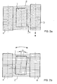
- Figure 4 is a perspective view of a second mode of execution.
- Figure 5 is a perspective view of a third mode of execution.
- a workpiece 1 is resting against a layer of wires 2 supported by wire guide cylinders 4.5.
- the support table 3 on which is fixed the workpiece 1 moves in the direction 6.
- the wire guide cylinder 4 is fixed while the cylinder wire guide 5 can move axially giving rotation angular to the rotary ply 2 with respect to the workpiece 1.
- Figure 1b illustrates in perspective the principle of the rotary support table known and currently used as a means of alignment.
- the workpiece 1 is set support against the ply of wires 2 supported by the cylinders fixed wire guides 4.
- a turntable 7 is interposed between the support table 3 and the workpiece 1.
- Support table 3 on which the turntable is fixed 7 and the workpiece 1 moves in the direction 6.
- the workpiece 1 can rotate on its axis by an angle a thanks to the turntable 7.
- Figure 2a shows schematically seen from above a possibility of realizing the principle of the present invention.
- the rotary ply of wires 2 can be angularly adjusted by an angle a by the displacement of the thread guide adjustable 5 relative to the fixed wire guide 4.
- the part to be saw 1 is fixed.
- Figure 2b shows schematically seen from above the known principle used to date.
- the workpiece 1 mounted on the rotary support table can rotate according to a angle a with respect to the fixed ply of wires 2 maintained by fixed wire guides 4.
- the longitudinal section in Figure 3 shows a example of a mechanism allowing the axial displacement of a thread guide cylinders 5 for adjusting the ply of rotating wire.
- the thread guide cylinder 5 is mounted rotating around the fixed axis 8 via the bearings 9.
- the fixed bearing 10 consists of a threaded flange 11 fixed to the frame (not shown) of the sawing device and cooperating with a threaded part of the fixed axis 8, of a tightening nut 12 and a square termination 13 allowing the adjustment of the position of the axis 8 therefore of the wire guide 5.
- the fixed axis 8 is held in the flange 21 secured to the frame, but can slide axially in the latter.
- the square ending 13 can be turned for the angular adjustment of the ply of wires by all means 22, for example manually using a key, electrically by an electric motor or by pneumatic or hydraulic means. After adjustment, the clamping nut 12 is pressed against the threaded flange 11 so as to lock the axis 8 in its axial position adjusted.
- the wire guide cylinders 4 are fixed on a plate 13.
- the plate 13 can rotate thanks to a hinge 14 around of an axis 15 perpendicular to the sheet of wires 2.
- a mechanism with screw 16 allows the angle of rotation a to be adjusted of the plate 13 relative to the frame 17 of the device sawing comprising the fixed support table 3 with the workpiece saw 1.
- An optical or video installation allows adjustment from angle a.
- This installation preferably includes two viewfinders 18 or two video cameras mounted on the frame 17 and capable of being moved parallel to the layer of wires 2.
- the augular orientation of the latter relative to the fixed support table 3 could be precisely adjusted by knowing the position occupied by the two optical viewfinders 18 or by the two cameras video.
- the embodiment illustrated in Figure 5 includes fixed 4 wire guide cylinders, as well as a support table 3 angularly fixed, but capable of being moved in a vertical direction 6 to urge the sawing piece 1 against the wire sheet 2.
- This embodiment includes a mechanism 24 for moving all or part of the wires in the wire layer 2 on the surface of minus one of the wire guide cylinders 4 by shifting the wires in other grooves provided on the surface of the cylinders.
- This mechanism 24 may include, for this purpose, a comb 25 likely to come into contact with the wires and offset laterally on the wire guide using a crank 26.
- This comb 25 can thus move simultaneously some or all of the wires.
- he may also be replaced by a body, such as a hook, intended to move wire by wire or by group of wires on the surface of one of the cylinders guide-son.
- the saw wire forming the sheet of wires 2 between the wire guide cylinders 4 is made of spring steel with a diameter between 0.1 and 0.2 mm in order to saw blocks of hard or exotic materials (such as silicon, ceramic materials, compounds of groups III-V, gadolinium-gallium garnets, sapphires, etc.) in slices approximately 0.1 to 5 mm thick.
- the agent abrasive is a commercial product and can be diamond, silicon carbide, alumina etc in the form fixed to the wire or in free slip form.
Landscapes
- Engineering & Computer Science (AREA)
- Mechanical Engineering (AREA)
- Processing Of Stones Or Stones Resemblance Materials (AREA)
- Finish Polishing, Edge Sharpening, And Grinding By Specific Grinding Devices (AREA)
- Sawing (AREA)
Claims (9)
- Drahtsägevorrichtung mit einer Drahtschicht (2), die zwischen mindestens zwei Drahtführungszylindern (4) gespannt und durch Rillen an Ort und Stelle gehalten wird, die in die Oberfläche der benannten Drahtführungszylinder (4) eingeschnitten sind und den Abstand zwischen den Drähten der benannten Drahtschicht (2) definieren, wobei die Drähte befähigt sind, sich hin- und hergehend oder kontinuierlich zu bewegen, während sie gegen ein zu sägendes Werkstück (1) drücken, das auf einen Auflagetisch (3) montiert ist, dadurch gekennzeichnet, dass sie Mittel umfasst, um die Drahtschicht (2) gegenüber dem winkelmässig feststehenden Auflagetisch (3) winkelmässig auszurichten und der benannten Drahtschicht (2) eine Funktion der Drehung gegenüber dem Auflagetisch (3) und somit gegenüber dem zu sägenden Werkstück (1) zu verleihen.
- Vorrichtung gemäss Anspruch 1, dadurch gekennzeichnet, dass die benannten Mittel durch einen Mechanismus realisiert werden, der dazu bestimmt ist, eine Drehung der Gesamtheit der auf einer Platte (13) befestigten Drahtführungen (4) zu bewirken, und dadurch, dass die benannte Platte (13) um eine zur Drahtschicht (2) senkrechte Achse (15) bezüglich des Auflagetisches (3) drehbar montiert ist.
- Vorrichtung gemäss Anspruch 1, dadurch gekennzeichnet, dass die benannten Mittel durch einen Mechanismus realisiert werden, der dazu bestimmt ist, eine Axialverschiebung zumindest eines einstellbaren Drahtführungszylinders (5) zu bewirken.
- Vorrichtung gemäss Anspruch 3, dadurch gekennzeichnet, dass der benannte Mechanismus, der dazu bestimmt ist, eine axiale Verschiebung zu bewirken, eine feststehende Achse (8) umfasst, auf die der Drahtführungszylinder (5) um diese Achse drehbar montiert ist, wobei die feststehende Achse (8) an ihren beiden Enden durch feststehende Lager (10, 21) gehalten wird und zumindest eines der feststehenden Lager (10) einen feststehenden Flansch mit Gewinde (11) umfasst, der dazu bestimmt ist, mit einem Gewindeabschnitt der feststehenden Achse (8) zusammenzuwirken, deren eines Ende (13) so gestaltet ist, dass es mit einem Betätigungs- und Regelorgan (22) zusammenwirken kann, wobei eine Stellmutter (12) dafür vorgesehen ist, mit dem feststehenden Gewindeflansch (11) so zusammenzuwirken, dass nach der Ausrichtung der Drahtschicht (2) die feststehende Achse (8) blockiert wird.
- Vorrichtung gemäss Anspruch 1, dadurch gekennzeichnet, dass die benannten Mittel durch einen Mechanismus in Gestalt eines Kammes realisiert werden, der so eingerichtet ist, dass er eine Versetzung der ganzen oder eines Teiles der Drahtschicht (2) auf der Oberfläche zumindest eines feststehenden Drahtführungszylinders (4) bewirkt.
- Vorrichtung gemäss Anspruch 1, dadurch gekennzeichnet, dass die benannten Mittel durch einen Mechanismus realisiert werden, der dazu bestimmt ist zu bewirken, dass auf der Oberfläche zumindest eines feststehenden Drahtführungszylinders (4) die Drähte der Drahtschicht (2) einer nach dem anderen bzw. als eine Drahtgruppe verschoben werden.
- Vorrichtung gemäss einem der Ansprüche 1 bis 5, dadurch gekennzeichnet, dass die benannten Mittel manuell, elektrisch, pneumatisch oder hydraulisch betätigt werden.
- Vorrichtung gemäss einem der Ansprüche 1 bis 7, dadurch gekennzeichnet, dass sie zumindest ein optisches Organ umfasst, das auf einen feststehenden Abschnitt der Vorrichtung montiert und dazu bestimmt ist, die winkelmässige Ausrichtung der Drahtschicht (2) bezüglich des Auflagetisches (3) zu überwachen.
- Vorrichtung gemäss einem der Ansprüche 1 bis 7, dadurch gekennzeichnet, dass sie zumindest eine Videokamera umfasst, die auf einen feststehenden Abschnitt der Vorrichtung montiert und dazu bestimmt ist, die winkelmässige Ausrichtung der Drahtschicht (2) bezüglich des Auflagetisches (3) zu überwachen.
Applications Claiming Priority (3)
| Application Number | Priority Date | Filing Date | Title |
|---|---|---|---|
| CH01295/96A CH690907A5 (fr) | 1996-05-23 | 1996-05-23 | Dispositif de sciage par fil |
| CH1295/96 | 1996-05-23 | ||
| CH129596 | 1996-05-23 |
Publications (3)
| Publication Number | Publication Date |
|---|---|
| EP0808701A2 EP0808701A2 (de) | 1997-11-26 |
| EP0808701A3 EP0808701A3 (de) | 1998-04-08 |
| EP0808701B1 true EP0808701B1 (de) | 2002-12-04 |
Family
ID=4207094
Family Applications (1)
| Application Number | Title | Priority Date | Filing Date |
|---|---|---|---|
| EP97107978A Expired - Lifetime EP0808701B1 (de) | 1996-05-23 | 1997-05-16 | Drahtsäge |
Country Status (5)
| Country | Link |
|---|---|
| US (1) | US5913305A (de) |
| EP (1) | EP0808701B1 (de) |
| JP (1) | JPH1080854A (de) |
| CH (1) | CH690907A5 (de) |
| DE (1) | DE69717536T2 (de) |
Cited By (3)
| Publication number | Priority date | Publication date | Assignee | Title |
|---|---|---|---|---|
| US8425640B2 (en) | 2009-08-14 | 2013-04-23 | Saint-Gobain Abrasives, Inc. | Abrasive articles including abrasive particles bonded to an elongated body |
| US9028948B2 (en) | 2009-08-14 | 2015-05-12 | Saint-Gobain Abrasives, Inc. | Abrasive articles including abrasive particles bonded to an elongated body, and methods of forming thereof |
| CN105235077A (zh) * | 2015-09-30 | 2016-01-13 | 浙江辉弘光电能源有限公司 | 一种金刚线切割机用轴辊固定装置 |
Families Citing this family (29)
| Publication number | Priority date | Publication date | Assignee | Title |
|---|---|---|---|---|
| DE69808072T2 (de) * | 1997-05-07 | 2003-05-08 | Hct Shaping Systems Sa, Cheseaux | Drahtsäge zum schneiden von dünnen scheiben mittels wenigstens zwei einander schneidenden sägedrahtgeweben |
| US6333377B1 (en) * | 1999-03-08 | 2001-12-25 | A&A Material Corporation | Ingot support device for slicing silicon |
| DE60033574T2 (de) | 2000-05-31 | 2007-11-15 | Memc Electronic Materials S.P.A. | Drahtsäge und verfahren zum gleichzeitigen schneiden von halbleiterbarren |
| CH697024A5 (fr) * | 2000-09-28 | 2008-03-31 | Hct Shaping Systems Sa | Dispositif de sciage par fil. |
| DE10052154A1 (de) * | 2000-10-20 | 2002-05-08 | Freiberger Compound Mat Gmbh | Verfahren und Vorrichtung zum Trennen von Einkristallen, Justiervorrichtung und Testverfahren zum Ermitteln einer Orientierung eines Einkristalls für ein derartiges Verfahren |
| JP2003071703A (ja) * | 2001-09-05 | 2003-03-12 | Seiko Instruments Inc | 多段式微小孔加工方法および装置 |
| EP1819473A1 (de) * | 2004-12-10 | 2007-08-22 | Freiberger Compound Materials GmbH | Werkst]ckhalterung und verfahren zum drahts[gen |
| WO2009001453A1 (ja) * | 2007-06-27 | 2008-12-31 | Mitsubishi Electric Corporation | マルチワイヤソーおよびインゴットの切断方法 |
| JP2010023225A (ja) * | 2008-06-20 | 2010-02-04 | Komatsu Ntc Ltd | ワイヤソー |
| US20100126488A1 (en) * | 2008-11-25 | 2010-05-27 | Abhaya Kumar Bakshi | Method and apparatus for cutting wafers by wire sawing |
| IT1393227B1 (it) * | 2009-02-27 | 2012-04-11 | Bidese | Dispositivo di protezione per macchine multifilo per il taglio di materiali lapidei, nonche' macchina multiutensile comprendente tale dispositivo. |
| TWI466990B (zh) | 2010-12-30 | 2015-01-01 | 聖高拜磨料有限公司 | 磨料物品及形成方法 |
| KR101618040B1 (ko) | 2011-09-16 | 2016-05-04 | 생-고뱅 어브레이시브즈, 인코포레이티드 | 연마 물품 및 형성방법 |
| JP5869680B2 (ja) | 2011-09-29 | 2016-02-24 | サンーゴバン アブレイシブズ,インコーポレイティド | バリア層を有する細長い基板本体に結合した研磨粒子を含む研磨物品及びその形成方法 |
| CN102626805A (zh) * | 2012-02-14 | 2012-08-08 | 上海五同机械制造有限公司 | 一种线切割机工作台 |
| KR101385665B1 (ko) * | 2012-04-27 | 2014-04-21 | 한국생산기술연구원 | 잉곳의 스윙 중심축의 정렬이 용이하도록 구조가 개선된 잉곳 스윙방식의 와이어 쏘 |
| EP2664402A1 (de) * | 2012-05-18 | 2013-11-20 | Meyer Burger AG | Drahtsäge und Verfahren zum Schneiden von Werkstücken, insbesondere von Werkstücken aus hartem und sprödem Material |
| TW201404527A (zh) | 2012-06-29 | 2014-02-01 | 聖高拜磨料有限公司 | 研磨物品及形成方法 |
| TWI477343B (zh) | 2012-06-29 | 2015-03-21 | Saint Gobain Abrasives Inc | 研磨物品及形成方法 |
| TWI474889B (zh) | 2012-06-29 | 2015-03-01 | 聖高拜磨料有限公司 | 研磨物品及形成方法 |
| TW201402274A (zh) | 2012-06-29 | 2014-01-16 | 聖高拜磨料有限公司 | 研磨物品及形成方法 |
| TW201441355A (zh) | 2013-04-19 | 2014-11-01 | 聖高拜磨料有限公司 | 研磨製品及其形成方法 |
| DE102013219900B3 (de) * | 2013-10-01 | 2015-02-26 | Siltronic Ag | Verfahren zum Rillieren der Drahtführungsrollen für Drahtsägen zum Abtrennen von Scheiben von einem Werkstück |
| EP2933049A1 (de) * | 2014-04-17 | 2015-10-21 | Applied Materials Switzerland Sàrl | Drahtführungsüberwachungsvorrichtung und Verfahren zur Überwachung eines Führungsdrahts |
| US9205572B1 (en) * | 2014-05-28 | 2015-12-08 | National Tsing Hua University | Ingot cutting method capable of reducing wafer damage percentage |
| EP3098008A1 (de) * | 2015-05-29 | 2016-11-30 | Meyer Burger AG | Verfahren zur anordnung eines schnittdrahts |
| TWI664057B (zh) | 2015-06-29 | 2019-07-01 | 美商聖高拜磨料有限公司 | 研磨物品及形成方法 |
| US11276577B2 (en) * | 2019-03-21 | 2022-03-15 | Samuel Messinger | Longitudinal silicon ingot slicing apparatus |
| CN111251158A (zh) * | 2020-03-26 | 2020-06-09 | 义乌工商职业技术学院 | 一种建筑工程用瓷砖切断装置 |
Family Cites Families (8)
| Publication number | Priority date | Publication date | Assignee | Title |
|---|---|---|---|---|
| US3831576A (en) * | 1971-11-22 | 1974-08-27 | Motorola Inc | Machine and method for cutting brittle materials using a reciprocating cutting wire |
| JPH0626787B2 (ja) * | 1987-06-15 | 1994-04-13 | 日本鉱業株式会社 | 切断装置における傾き検出方法 |
| JP2673544B2 (ja) * | 1988-06-14 | 1997-11-05 | 株式会社日平トヤマ | 脆性材料の切断方法 |
| JP2516717B2 (ja) * | 1991-11-29 | 1996-07-24 | 信越半導体株式会社 | ワイヤソ―及びその切断方法 |
| JP2639270B2 (ja) * | 1991-12-19 | 1997-08-06 | 住友金属工業株式会社 | ワイヤソーによる切断方法 |
| CH690845A5 (de) * | 1994-05-19 | 2001-02-15 | Tokyo Seimitsu Co Ltd | Verfahren zum Positionieren eines Werkstücks und Vorrichtung hierfür. |
| JP3427956B2 (ja) * | 1995-04-14 | 2003-07-22 | 信越半導体株式会社 | ワイヤーソー装置 |
| JP3187295B2 (ja) * | 1995-08-31 | 2001-07-11 | 株式会社日平トヤマ | ワイヤソー装置 |
-
1996
- 1996-05-23 CH CH01295/96A patent/CH690907A5/fr not_active IP Right Cessation
-
1997
- 1997-05-16 EP EP97107978A patent/EP0808701B1/de not_active Expired - Lifetime
- 1997-05-16 DE DE69717536T patent/DE69717536T2/de not_active Expired - Lifetime
- 1997-05-22 JP JP9147046A patent/JPH1080854A/ja active Pending
- 1997-05-23 US US08/862,609 patent/US5913305A/en not_active Expired - Lifetime
Cited By (3)
| Publication number | Priority date | Publication date | Assignee | Title |
|---|---|---|---|---|
| US8425640B2 (en) | 2009-08-14 | 2013-04-23 | Saint-Gobain Abrasives, Inc. | Abrasive articles including abrasive particles bonded to an elongated body |
| US9028948B2 (en) | 2009-08-14 | 2015-05-12 | Saint-Gobain Abrasives, Inc. | Abrasive articles including abrasive particles bonded to an elongated body, and methods of forming thereof |
| CN105235077A (zh) * | 2015-09-30 | 2016-01-13 | 浙江辉弘光电能源有限公司 | 一种金刚线切割机用轴辊固定装置 |
Also Published As
| Publication number | Publication date |
|---|---|
| CH690907A5 (fr) | 2001-02-28 |
| DE69717536D1 (de) | 2003-01-16 |
| EP0808701A2 (de) | 1997-11-26 |
| DE69717536T2 (de) | 2003-08-21 |
| EP0808701A3 (de) | 1998-04-08 |
| US5913305A (en) | 1999-06-22 |
| JPH1080854A (ja) | 1998-03-31 |
Similar Documents
| Publication | Publication Date | Title |
|---|---|---|
| EP0808701B1 (de) | Drahtsäge | |
| EP0980303B1 (de) | Drahtsäge zum schneiden von dünnen scheiben mittels wenigstens zwei einander schneidenden sägedrahtgeweben | |
| EP0767036B1 (de) | Drahtsäge mit einem Drahtmanagementsystem dass eine Verwendung von Drahtzylindern sehr grosser Länge erlaubt | |
| EP1320438B1 (de) | Drahtsäge mit mitteln zum erzeugen einer zwischen werkstück und draht relativen oszillationsbewegung | |
| EP0788857B1 (de) | Drahtsägevorrichtung | |
| EP0640435A1 (de) | Schleifmaschine | |
| EP1054748B1 (de) | Drahtsäge zum schneiden von dünnen scheiben mittels wenigstens zwei einander schneidenden sägedrahtgeweben | |
| FR2719794A1 (fr) | Appareil de transfert de fil. | |
| EP0788859B1 (de) | Drahtsägevorrichtung | |
| CA2452060C (fr) | Dispositif de transport de pieces pour l'alimentation de machines | |
| FR2476527A1 (fr) | Dispositif de retenue de pieces pour les operations de honage | |
| EP0869858B1 (de) | Bearbeitungseinheit mit rotierendem kopf | |
| EP0795504A1 (de) | Maschine zum kontinuierlichen Abwickeln von Bobinen mit zumindest einer Einrichtung zum gleichzeitigen Abwickeln von zwei paarweise oder koaxial angeordneten Bobinen | |
| FR2629448A1 (fr) | Appareillage pour decouper une piece en un materiau du type verre ou ceramique le long d'une ligne incisee | |
| FR2630030A1 (fr) | Porte-monture de lunettes perfectionne pour machine a reproduire | |
| FR2814323A1 (fr) | Dispositif de reglage en hauteur de roues, en particulier pour machine d'entretien des pelouses | |
| FR2774933A1 (fr) | Dispositif de serrage | |
| FR2570122A1 (fr) | Dispositif de freinage pour immobiliser une table tournante, en particulier de fraiseuses-chargeuses et analogues | |
| CH667618A5 (fr) | Tete d'ecriture commutable. | |
| EP1038633B1 (de) | Vorrichtung zur Schleifbearbeitung von Werkstücken, insbesondere zur Feinstbearbeitung | |
| FR2825652A1 (fr) | Machine d'usinage par abrasif de portees d'une piece, notamment de superfinition de manetons de vilebrequins | |
| FR2655285A1 (fr) | Machine a affuter les couteaux. | |
| CH692329A5 (fr) | Dispositif de sciage par fil. | |
| FR2835775A1 (fr) | Dispositif de coupe d'au moins un element tubulaire au moyen d'un outil rotatif | |
| WO2004060699A1 (fr) | Machine a graver polaire |
Legal Events
| Date | Code | Title | Description |
|---|---|---|---|
| PUAI | Public reference made under article 153(3) epc to a published international application that has entered the european phase |
Free format text: ORIGINAL CODE: 0009012 |
|
| AK | Designated contracting states |
Kind code of ref document: A2 Designated state(s): DE FR GB IT |
|
| PUAL | Search report despatched |
Free format text: ORIGINAL CODE: 0009013 |
|
| AK | Designated contracting states |
Kind code of ref document: A3 Designated state(s): DE FR GB IT |
|
| RAP1 | Party data changed (applicant data changed or rights of an application transferred) |
Owner name: HCT SHAPING SYSTEMS SA |
|
| RIN1 | Information on inventor provided before grant (corrected) |
Inventor name: HAUSER, CHARLES |
|
| 17P | Request for examination filed |
Effective date: 19980715 |
|
| GRAG | Despatch of communication of intention to grant |
Free format text: ORIGINAL CODE: EPIDOS AGRA |
|
| 17Q | First examination report despatched |
Effective date: 20020424 |
|
| GRAG | Despatch of communication of intention to grant |
Free format text: ORIGINAL CODE: EPIDOS AGRA |
|
| GRAH | Despatch of communication of intention to grant a patent |
Free format text: ORIGINAL CODE: EPIDOS IGRA |
|
| GRAH | Despatch of communication of intention to grant a patent |
Free format text: ORIGINAL CODE: EPIDOS IGRA |
|
| GRAA | (expected) grant |
Free format text: ORIGINAL CODE: 0009210 |
|
| AK | Designated contracting states |
Kind code of ref document: B1 Designated state(s): DE FR GB IT |
|
| REG | Reference to a national code |
Ref country code: GB Ref legal event code: FG4D Free format text: NOT ENGLISH |
|
| REF | Corresponds to: |
Ref document number: 69717536 Country of ref document: DE Date of ref document: 20030116 |
|
| GBT | Gb: translation of ep patent filed (gb section 77(6)(a)/1977) |
Effective date: 20030325 |
|
| PLBE | No opposition filed within time limit |
Free format text: ORIGINAL CODE: 0009261 |
|
| STAA | Information on the status of an ep patent application or granted ep patent |
Free format text: STATUS: NO OPPOSITION FILED WITHIN TIME LIMIT |
|
| 26N | No opposition filed |
Effective date: 20030905 |
|
| REG | Reference to a national code |
Ref country code: FR Ref legal event code: CD |
|
| PGFP | Annual fee paid to national office [announced via postgrant information from national office to epo] |
Ref country code: FR Payment date: 20110607 Year of fee payment: 15 |
|
| PGFP | Annual fee paid to national office [announced via postgrant information from national office to epo] |
Ref country code: GB Payment date: 20110520 Year of fee payment: 15 |
|
| PGFP | Annual fee paid to national office [announced via postgrant information from national office to epo] |
Ref country code: IT Payment date: 20110527 Year of fee payment: 15 Ref country code: DE Payment date: 20110520 Year of fee payment: 15 |
|
| GBPC | Gb: european patent ceased through non-payment of renewal fee |
Effective date: 20120516 |
|
| PG25 | Lapsed in a contracting state [announced via postgrant information from national office to epo] |
Ref country code: IT Free format text: LAPSE BECAUSE OF NON-PAYMENT OF DUE FEES Effective date: 20120516 |
|
| REG | Reference to a national code |
Ref country code: FR Ref legal event code: ST Effective date: 20130131 |
|
| REG | Reference to a national code |
Ref country code: DE Ref legal event code: R119 Ref document number: 69717536 Country of ref document: DE Effective date: 20121201 |
|
| PG25 | Lapsed in a contracting state [announced via postgrant information from national office to epo] |
Ref country code: FR Free format text: LAPSE BECAUSE OF NON-PAYMENT OF DUE FEES Effective date: 20120531 Ref country code: GB Free format text: LAPSE BECAUSE OF NON-PAYMENT OF DUE FEES Effective date: 20120516 |
|
| PG25 | Lapsed in a contracting state [announced via postgrant information from national office to epo] |
Ref country code: DE Free format text: LAPSE BECAUSE OF NON-PAYMENT OF DUE FEES Effective date: 20121201 |