EP0808701B1 - Wire saw - Google Patents
Wire saw Download PDFInfo
- Publication number
- EP0808701B1 EP0808701B1 EP97107978A EP97107978A EP0808701B1 EP 0808701 B1 EP0808701 B1 EP 0808701B1 EP 97107978 A EP97107978 A EP 97107978A EP 97107978 A EP97107978 A EP 97107978A EP 0808701 B1 EP0808701 B1 EP 0808701B1
- Authority
- EP
- European Patent Office
- Prior art keywords
- wires
- fixed
- web
- wire
- support table
- Prior art date
- Legal status (The legal status is an assumption and is not a legal conclusion. Google has not performed a legal analysis and makes no representation as to the accuracy of the status listed.)
- Expired - Lifetime
Links
- 230000007246 mechanism Effects 0.000 claims description 10
- 230000003287 optical effect Effects 0.000 claims description 8
- 238000006073 displacement reaction Methods 0.000 claims description 6
- 238000009434 installation Methods 0.000 description 4
- 238000004519 manufacturing process Methods 0.000 description 3
- 239000003795 chemical substances by application Substances 0.000 description 2
- 239000013078 crystal Substances 0.000 description 2
- 230000010354 integration Effects 0.000 description 2
- 229910000639 Spring steel Inorganic materials 0.000 description 1
- PNEYBMLMFCGWSK-UHFFFAOYSA-N aluminium oxide Inorganic materials [O-2].[O-2].[O-2].[Al+3].[Al+3] PNEYBMLMFCGWSK-UHFFFAOYSA-N 0.000 description 1
- 229910010293 ceramic material Inorganic materials 0.000 description 1
- 239000013065 commercial product Substances 0.000 description 1
- 150000001875 compounds Chemical class 0.000 description 1
- 238000010276 construction Methods 0.000 description 1
- 238000012937 correction Methods 0.000 description 1
- 230000001419 dependent effect Effects 0.000 description 1
- 229910003460 diamond Inorganic materials 0.000 description 1
- 239000010432 diamond Substances 0.000 description 1
- 229910052733 gallium Inorganic materials 0.000 description 1
- 238000003780 insertion Methods 0.000 description 1
- 230000037431 insertion Effects 0.000 description 1
- 239000000463 material Substances 0.000 description 1
- 238000000034 method Methods 0.000 description 1
- 230000000284 resting effect Effects 0.000 description 1
- 229910052710 silicon Inorganic materials 0.000 description 1
- 239000010703 silicon Substances 0.000 description 1
- HBMJWWWQQXIZIP-UHFFFAOYSA-N silicon carbide Chemical compound [Si+]#[C-] HBMJWWWQQXIZIP-UHFFFAOYSA-N 0.000 description 1
- 229910010271 silicon carbide Inorganic materials 0.000 description 1
- 230000008685 targeting Effects 0.000 description 1
Images


Classifications
-
- B—PERFORMING OPERATIONS; TRANSPORTING
- B28—WORKING CEMENT, CLAY, OR STONE
- B28D—WORKING STONE OR STONE-LIKE MATERIALS
- B28D5/00—Fine working of gems, jewels, crystals, e.g. of semiconductor material; apparatus or devices therefor
- B28D5/0058—Accessories specially adapted for use with machines for fine working of gems, jewels, crystals, e.g. of semiconductor material
- B28D5/0082—Accessories specially adapted for use with machines for fine working of gems, jewels, crystals, e.g. of semiconductor material for supporting, holding, feeding, conveying or discharging work
- B28D5/0088—Accessories specially adapted for use with machines for fine working of gems, jewels, crystals, e.g. of semiconductor material for supporting, holding, feeding, conveying or discharging work the supporting or holding device being angularly adjustable
-
- B—PERFORMING OPERATIONS; TRANSPORTING
- B23—MACHINE TOOLS; METAL-WORKING NOT OTHERWISE PROVIDED FOR
- B23D—PLANING; SLOTTING; SHEARING; BROACHING; SAWING; FILING; SCRAPING; LIKE OPERATIONS FOR WORKING METAL BY REMOVING MATERIAL, NOT OTHERWISE PROVIDED FOR
- B23D57/00—Sawing machines or sawing devices not covered by one of the preceding groups B23D45/00 - B23D55/00
- B23D57/003—Sawing machines or sawing devices working with saw wires, characterised only by constructional features of particular parts
- B23D57/0053—Sawing machines or sawing devices working with saw wires, characterised only by constructional features of particular parts of drives for saw wires; of wheel mountings; of wheels
-
- B—PERFORMING OPERATIONS; TRANSPORTING
- B23—MACHINE TOOLS; METAL-WORKING NOT OTHERWISE PROVIDED FOR
- B23D—PLANING; SLOTTING; SHEARING; BROACHING; SAWING; FILING; SCRAPING; LIKE OPERATIONS FOR WORKING METAL BY REMOVING MATERIAL, NOT OTHERWISE PROVIDED FOR
- B23D57/00—Sawing machines or sawing devices not covered by one of the preceding groups B23D45/00 - B23D55/00
- B23D57/003—Sawing machines or sawing devices working with saw wires, characterised only by constructional features of particular parts
- B23D57/0061—Sawing machines or sawing devices working with saw wires, characterised only by constructional features of particular parts of devices for guiding or feeding saw wires
Definitions
- the present invention relates to a device for wire sawing comprising a sheet of wire stretched between at least two wire guide cylinders and held in position by grooves cut on the surface of said cylinders wire guides which define the interval between son of said layer of son, the son being susceptible to move in an alternating or continuous movement while support against a workpiece fixed on a support table.
- the sawing area is consisting of a set of cylinders placed in parallel. These cylinders, called wire guides, are engraved with grooves defining the interval between the wires of the tablecloth, the thickness of the slices.
- the workpiece is fixed on a support table which moves perpendicularly to the layer of wires. Travel speed defines the cutting speed.
- the renewal of the thread, as well as the control of its tension is done in a part called the wire management area outside the sawing area proper.
- the agent who will govern the cutting is either an abrasive attached to the wire, or an abrasive free brought in slip form.
- the wire only acts as a transporter.
- the tensioned wire is both guided and pulled by the thread guide cylinders.
- These generally coated cylinders of a synthetic layer are engraved with grooves including the geometry and dimensions must be of great precision.
- the direction of sawing is of great importance, so also the direction of the wire with respect to the single crystal himself and consequently compared to the table support of the workpiece.
- a device for adjusting the support table by relation to the son of the tablecloth is generally planned and carried out in the form of a rotating turntable placed between the machine and the support table. The support table then becomes rotary table.
- the object of the present invention is to remedy these disadvantages and it is characterized for this purpose by the sawing device includes means for angularly orient the sheet of wires with respect to the angularly fixed support table and to give said ply of wires a rotation function with respect to the support table, therefore relative to the workpiece.
- the height and size of the sawing device can be reduced. Transport and installation of the device are facilitated. The manufacturing price and the number of pieces can be kept low while getting a whole more easy to use, more rigid and therefore more robust.
- Case 1 corresponds to known devices.
- the case 3) has no advantage because it combines the disadvantages of the first two methods.
- case 2 by aligning the ply of wires with respect to at the fixed table presents a new concept of rotary thread which can be made by turning the web son itself, for example by means of a translation axial of one of the wire guides adjacent to the workpiece.
- This translation of one of the adjacent wire guides will cause a rotation of the direction of the tablecloth threads allowing it to be aligned with the support table.
- the axial translation of one of the wire guides can be performed mechanically, manually or electrically, by example with the help of a screw centered on the wire guide, or hydraulic or pneumatic by a corresponding jack.
- the support table moving along a perpendicular axis adjusting the orientation of the rotating web of wires of the rotary ply of wires with respect to the support table can then be easily controlled using a system single or double optical or video integrated in the fixed part of the sawing device and aimed at a direction parallel to the axis of movement of the table support.
- the two objectives of a system optical or the two cameras of a video system will be positioned on a direction parallel to the direction of wires of the rotary wire table in their position final work.
- the sawing device according to the invention by its concept of rotating wire layer, allows to orient the ply of threads relative to the support table by carrying out a rotation of the ply of wires, thus limiting the number of mechanical parts required compared to the rotary table, and decrease the complexity of the whole while increasing the rigidity of the sawing device.
- the permanent integration of an optical system or video control facilitates the operator's task while minimizing the risk of adjustment errors.
- Figure 1a is a perspective view of a first mode of execution.
- Figure 1b illustrates in perspective a device known.
- FIGS. 2a and 2b respectively are views of the ply of wire and the workpiece of Figure 1a, respectively of Figure 1b.
- Figure 3 shows a detailed section through a wire guide cylinder of Figure 1a.
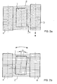
- Figure 4 is a perspective view of a second mode of execution.
- Figure 5 is a perspective view of a third mode of execution.
- a workpiece 1 is resting against a layer of wires 2 supported by wire guide cylinders 4.5.
- the support table 3 on which is fixed the workpiece 1 moves in the direction 6.
- the wire guide cylinder 4 is fixed while the cylinder wire guide 5 can move axially giving rotation angular to the rotary ply 2 with respect to the workpiece 1.
- Figure 1b illustrates in perspective the principle of the rotary support table known and currently used as a means of alignment.
- the workpiece 1 is set support against the ply of wires 2 supported by the cylinders fixed wire guides 4.
- a turntable 7 is interposed between the support table 3 and the workpiece 1.
- Support table 3 on which the turntable is fixed 7 and the workpiece 1 moves in the direction 6.
- the workpiece 1 can rotate on its axis by an angle a thanks to the turntable 7.
- Figure 2a shows schematically seen from above a possibility of realizing the principle of the present invention.
- the rotary ply of wires 2 can be angularly adjusted by an angle a by the displacement of the thread guide adjustable 5 relative to the fixed wire guide 4.
- the part to be saw 1 is fixed.
- Figure 2b shows schematically seen from above the known principle used to date.
- the workpiece 1 mounted on the rotary support table can rotate according to a angle a with respect to the fixed ply of wires 2 maintained by fixed wire guides 4.
- the longitudinal section in Figure 3 shows a example of a mechanism allowing the axial displacement of a thread guide cylinders 5 for adjusting the ply of rotating wire.
- the thread guide cylinder 5 is mounted rotating around the fixed axis 8 via the bearings 9.
- the fixed bearing 10 consists of a threaded flange 11 fixed to the frame (not shown) of the sawing device and cooperating with a threaded part of the fixed axis 8, of a tightening nut 12 and a square termination 13 allowing the adjustment of the position of the axis 8 therefore of the wire guide 5.
- the fixed axis 8 is held in the flange 21 secured to the frame, but can slide axially in the latter.
- the square ending 13 can be turned for the angular adjustment of the ply of wires by all means 22, for example manually using a key, electrically by an electric motor or by pneumatic or hydraulic means. After adjustment, the clamping nut 12 is pressed against the threaded flange 11 so as to lock the axis 8 in its axial position adjusted.
- the wire guide cylinders 4 are fixed on a plate 13.
- the plate 13 can rotate thanks to a hinge 14 around of an axis 15 perpendicular to the sheet of wires 2.
- a mechanism with screw 16 allows the angle of rotation a to be adjusted of the plate 13 relative to the frame 17 of the device sawing comprising the fixed support table 3 with the workpiece saw 1.
- An optical or video installation allows adjustment from angle a.
- This installation preferably includes two viewfinders 18 or two video cameras mounted on the frame 17 and capable of being moved parallel to the layer of wires 2.
- the augular orientation of the latter relative to the fixed support table 3 could be precisely adjusted by knowing the position occupied by the two optical viewfinders 18 or by the two cameras video.
- the embodiment illustrated in Figure 5 includes fixed 4 wire guide cylinders, as well as a support table 3 angularly fixed, but capable of being moved in a vertical direction 6 to urge the sawing piece 1 against the wire sheet 2.
- This embodiment includes a mechanism 24 for moving all or part of the wires in the wire layer 2 on the surface of minus one of the wire guide cylinders 4 by shifting the wires in other grooves provided on the surface of the cylinders.
- This mechanism 24 may include, for this purpose, a comb 25 likely to come into contact with the wires and offset laterally on the wire guide using a crank 26.
- This comb 25 can thus move simultaneously some or all of the wires.
- he may also be replaced by a body, such as a hook, intended to move wire by wire or by group of wires on the surface of one of the cylinders guide-son.
- the saw wire forming the sheet of wires 2 between the wire guide cylinders 4 is made of spring steel with a diameter between 0.1 and 0.2 mm in order to saw blocks of hard or exotic materials (such as silicon, ceramic materials, compounds of groups III-V, gadolinium-gallium garnets, sapphires, etc.) in slices approximately 0.1 to 5 mm thick.
- the agent abrasive is a commercial product and can be diamond, silicon carbide, alumina etc in the form fixed to the wire or in free slip form.
Landscapes
- Engineering & Computer Science (AREA)
- Mechanical Engineering (AREA)
- Processing Of Stones Or Stones Resemblance Materials (AREA)
- Finish Polishing, Edge Sharpening, And Grinding By Specific Grinding Devices (AREA)
- Sawing (AREA)
Description
La présente invention concerne un dispositif de sciage par fil comprenant une nappe de fils tendue entre au moins deux cylindres guide-fils et maintenue en position par des gorges taillées sur la surface desdits cylindres guide-fils qui définissent l'intervalle entre les fils de ladite nappe de fils, les fils étant susceptibles de se déplacer selon un mouvement alternatif ou continu en appui contre une pièce à scier fixée sur une table support.The present invention relates to a device for wire sawing comprising a sheet of wire stretched between at least two wire guide cylinders and held in position by grooves cut on the surface of said cylinders wire guides which define the interval between son of said layer of son, the son being susceptible to move in an alternating or continuous movement while support against a workpiece fixed on a support table.
Dans les dispositifs connus (voir par example DE 195 17 107 A1), la zone de sciage est constituée d'un ensemble de cylindres placés parallèlement. Ces cylindres, appelés guide-fils, sont gravés avec des gorges définissant l'intervalle entre les fils de la nappe, soit l'épaisseur des tranches. La pièce à scier est fixée sur une table support qui se déplace perpendiculairement à la nappe de fils. La vitesse de déplacement définit la vitesse de coupe. Le renouvellement du fil, ainsi que le contrôle de sa tension se fait dans une partie appelée zone de gestion du fil située en dehors de la zone de sciage proprement dite. L'agent qui régira la découpe est soit un abrasif fixé sur le fil, soit un abrasif libre amené sous forme de barbotine. Le fil n'agit que comme transporteur.In known devices (see for example DE 195 17 107 A1), the sawing area is consisting of a set of cylinders placed in parallel. These cylinders, called wire guides, are engraved with grooves defining the interval between the wires of the tablecloth, the thickness of the slices. The workpiece is fixed on a support table which moves perpendicularly to the layer of wires. Travel speed defines the cutting speed. The renewal of the thread, as well as the control of its tension is done in a part called the wire management area outside the sawing area proper. The agent who will govern the cutting is either an abrasive attached to the wire, or an abrasive free brought in slip form. The wire only acts as a transporter.
Lors de la découpe en tranches fines de la pièce à scier, le fil tendu est à la fois guidé et tracté par les cylindres guide-fils. Ces cylindres généralement revêtus d'une couche synthétique sont gravés avec des gorges dont la géométrie et les dimensions doivent être d'une grande précision. De plus, lorsque la pièce à scier est un mon-cristal, la direction de sciage a une grande importance, donc également la direction du fil par rapport au mono-cristal lui-même et conséquemment par rapport à la table support de la pièce à scier. Pour obtenir une grande précision, un dispositif de réglage de la table support par rapport aux fils de la nappe est généralement prévu et réalisé sous la forme d'un plateau tournant réglable en rotation placé entre la machine et la table support. La table support devient alors table rotative. Dans la plupart des cas cette rotation est utilisée comme réglage fin, l'orientation principale est réalisée extérieurement au dispositif de sciage et le réglage fin ne dépasse guère quelques degrés. La mise en oeuvre d'un plateau rotatif de grande précision et sans jeu dans un milieu pollué par de l'abrasif pose quelques difficultés notamment en ce qui concerne sa protection. De plus, la superposition d'éléments mécaniques situés sous la pièce à scier diminue la rigidité donc la précision générale du dispositif de sciage. La place prévue pour l'insertion de l'élément mécanique rotatif destiné à l'orientation du fil par rapport à la table support augmente la hauteur, le poids et l'encombrement général du dispositif de sciage, donc les difficultés d'implantation, de transport et son prix de fabrication, étant donné le nombre de pièces élevé.When cutting the workpiece into thin slices sawing, the tensioned wire is both guided and pulled by the thread guide cylinders. These generally coated cylinders of a synthetic layer are engraved with grooves including the geometry and dimensions must be of great precision. In addition, when the workpiece is a crystal, the direction of sawing is of great importance, so also the direction of the wire with respect to the single crystal himself and consequently compared to the table support of the workpiece. To get great accuracy, a device for adjusting the support table by relation to the son of the tablecloth is generally planned and carried out in the form of a rotating turntable placed between the machine and the support table. The support table then becomes rotary table. Most of them cases this rotation is used as a setting end, the main orientation is carried out externally to the sawing device and the fine adjustment hardly exceeds a few degrees. The implementation of a turntable high precision and without play in an environment polluted by the abrasive poses some difficulties, particularly with regard to concerns its protection. In addition, the superimposition of elements under the workpiece reduces the rigidity therefore the general precision of the device sawing. The space provided for the insertion of the mechanical element rotary for orientation of the wire relative at the support table increases height, weight and size general of the sawing device, so the difficulties location, transport and its manufacturing price, given the high number of pieces.
La présente invention a pour but de remédier à ces inconvénients et elle est caractérisée à cet effet par le fait que le dispositif de sciage comprend des moyens pour orienter angulairement la nappe de fils par rapport à la table support angulairement fixe et pour conférer à ladite nappe de fils une fonction de rotation par rapport à la table support, donc par rapport à la pièce à scier.The object of the present invention is to remedy these disadvantages and it is characterized for this purpose by the the sawing device includes means for angularly orient the sheet of wires with respect to the angularly fixed support table and to give said ply of wires a rotation function with respect to the support table, therefore relative to the workpiece.
Par ces caractéristiques, la hauteur et l'encombrement général du dispositif de sciage peuvent être réduits. Le transport et l'implantation du dispositif sont facilités. Le prix de fabrication et le nombre de pièces peuvent être maintenus bas, tout en obtenant un ensemble plus simple d'emploi, plus rigide donc plus robuste.By these characteristics, the height and size of the sawing device can be reduced. Transport and installation of the device are facilitated. The manufacturing price and the number of pieces can be kept low while getting a whole more easy to use, more rigid and therefore more robust.
De manière générale, l'alignement en direction de la
table support avec la nappe de fils peut être réalisé de
trois manières différentes.
Le cas 1) correspond aux dispositifs connus. Le cas 3) ne présente aucun avantage car il cumule les inconvénients des deux premières méthodes.Case 1) corresponds to known devices. The case 3) has no advantage because it combines the disadvantages of the first two methods.
Par contre, pour un alignement en direction qui ne nécessite en général pas de grandes corrections, le cas 2) en réalisant l'alignement de la nappe de fils par rapport à la table fixe présente un concept nouveau de nappe de fils rotative qui peut être réalisé en tournant la nappe de fils elle-même, au moyen par exemple d'une translation axiale de l'un des guide-fils adjacent à la pièce à scier. Cette translation de l'un des guide-fils adjacent va entraíner une rotation de la direction des fils de la nappe permettant ainsi de l'aligner avec la table support. La translation axiale de l'un des guide-fils peut être effectuée de manière mécanique, manuelle ou électrique, par exemple avec l'aide d'une vis centrée sur le guide-fils, ou hydraulique ou pneumatique par un vérin correspondant. La table support se déplaçant selon un axe perpendiculaire à la nappe de fils rotative, le réglage de l'orientation de la nappe de fils rotative par rapport à la table support peut être alors aisément contrôlé à l'aide d'un système optique ou vidéo simple ou double intégré dans la partie fixe du dispositif de sciage et visant selon une direction parallèle à l'axe de déplacement de la table support. De préférence, les deux objectifs d'un système optique ou les deux caméras d'un système vidéo seront positionnés sur une direction parallèle à la direction des fils de la nappe de fils rotative dans leur position finale de travail.On the other hand, for an alignment in direction which does not usually requires no major corrections, case 2) by aligning the ply of wires with respect to at the fixed table presents a new concept of rotary thread which can be made by turning the web son itself, for example by means of a translation axial of one of the wire guides adjacent to the workpiece. This translation of one of the adjacent wire guides will cause a rotation of the direction of the tablecloth threads allowing it to be aligned with the support table. The axial translation of one of the wire guides can be performed mechanically, manually or electrically, by example with the help of a screw centered on the wire guide, or hydraulic or pneumatic by a corresponding jack. The support table moving along a perpendicular axis adjusting the orientation of the rotating web of wires of the rotary ply of wires with respect to the support table can then be easily controlled using a system single or double optical or video integrated in the fixed part of the sawing device and aimed at a direction parallel to the axis of movement of the table support. Preferably, the two objectives of a system optical or the two cameras of a video system will be positioned on a direction parallel to the direction of wires of the rotary wire table in their position final work.
L'utilisation d'une table rotative ne permet pas une intégration aisée dans la partie fixe du dispositif de sciage, d'un système optique ou vidéo de contrôle. Celui-ci devrait être intégré dans la partie rotative, ce qui complique considérablement la construction.The use of a rotary table does not allow easy integration into the fixed part of the sawing, optical or video control system. This one should be integrated into the rotating part, which considerably complicates construction.
Le dispositif de sciage selon l'invention, de par son concept de nappe de fils rotative, permet d'orienter la nappe de fils par rapport à la table support en effectuant une rotation de la nappe de fils, de limiter ainsi le nombre de pièces mécaniques nécessaires par rapport à la table rotative, et de diminuer la complexité de l'ensemble tout en augmentant la rigidité du dispositif de sciage. De plus, l'intégration permanente d'un système optique ou vidéo de contrôle facilite la tâche de l'opérateur tout en minimisant les risques d'erreurs de réglage.The sawing device according to the invention, by its concept of rotating wire layer, allows to orient the ply of threads relative to the support table by carrying out a rotation of the ply of wires, thus limiting the number of mechanical parts required compared to the rotary table, and decrease the complexity of the whole while increasing the rigidity of the sawing device. Of plus, the permanent integration of an optical system or video control facilitates the operator's task while minimizing the risk of adjustment errors.
L'utilisation du concept de nappe de fils rotative permet donc de réaliser un dispositif de sciage performant ayant une productivité élevée, une précision moyenne accrue par l'augmentation de la rigidité et permettant aisément de régler l'alignement de la table support par la rotation de la nappe de fils rotative.The use of the concept of rotating wire web therefore enables an efficient sawing device to be produced having high productivity, medium precision increased by increasing rigidity and allowing easily to adjust the alignment of the support table by the rotation of the rotating wire web.
D'autres avantages ressortent des caractéristiques exprimées dans les revendications dépendantes et de la description exposant ci-après l'invention plus en détail à l'aide de dessins qui représentent schématiquement et à titre d'exemple différents modes d'exécution.Other advantages emerge from the characteristics expressed in the dependent claims and the description setting out the invention below in more detail at using drawings which represent schematically and at as an example different modes of execution.
La figure 1a est une vue en perspective d'un premier mode d'exécution.Figure 1a is a perspective view of a first mode of execution.
La figure 1b illustre en perspective un dispositif connu.Figure 1b illustrates in perspective a device known.
Les figures 2a, respectivement 2b sont des vues de la nappe de fils et de la pièce à scier de la figure 1a, respectivement de la figure 1b.FIGS. 2a and 2b respectively are views of the ply of wire and the workpiece of Figure 1a, respectively of Figure 1b.
La figure 3 représente une coupe détaillée à travers un cylindre guide-fils de la figure 1a.Figure 3 shows a detailed section through a wire guide cylinder of Figure 1a.
La figure 4 est une vue en perspective d'un second mode d'exécution.Figure 4 is a perspective view of a second mode of execution.
La figure 5 est une vue en perspective d'un troisième mode d'exécution.Figure 5 is a perspective view of a third mode of execution.
En référence à la figure 1a, une pièce à scier 1 est
mise en appui contre une nappe de fils 2 supportée par des
cylindres guide-fils 4,5. La table support 3 sur laquelle
est fixée la pièce à scier 1 se déplace selon la direction
6. Le cylindre guide-fils 4 est fixe alors que le cylindre
guide-fils 5 peut se déplacer axialement donnant une rotation
angulaire à la nappe de fils rotative 2 par rapport à
la pièce à scier 1.Referring to Figure 1a, a
La figure 1b illustre en perspective le principe de
la table support rotative connue et utilisée actuellement
comme moyen d'alignement. La pièce à scier 1 est mise en
appui contre la nappe de fils 2 supportée par les cylindres
guide-fils fixes 4. Un plateau rotatif 7 est
intercalé entre la table support 3 et la pièce à scier 1.
La table support 3 sur laquelle est fixé le plateau rotatif
7 et la pièce à scier 1 se déplace selon la direction
6. La pièce à scier 1 peut tourner sur son axe d'un angle
a grâce au plateau rotatif 7.Figure 1b illustrates in perspective the principle of
the rotary support table known and currently used
as a means of alignment. The
La figure 2a représente schématiquement vu de dessus
une possibilité de réaliser le principe de la présente invention.
La nappe de fils rotative 2 peut être angulairement
ajustée d'un angle a par le déplacement du guide-fils
réglable 5 par rapport au guide-fils fixe 4. La pièce à
scier 1 est fixe.Figure 2a shows schematically seen from above
a possibility of realizing the principle of the present invention.
The rotary ply of
La figure 2b représente schématiquement vu de dessus
le principe connu utilisé à ce jour. La pièce à scier 1
montée sur la table support rotative peut tourner selon un
angle a par rapport à la nappe de fils fixe 2 maintenue
par des guide-fils fixes 4.Figure 2b shows schematically seen from above
the known principle used to date. The
La coupe longitudinale de la figure 3 montre un
exemple de mécanisme permettant le déplacement axial d'un
des cylindres guide-fils 5 pour le réglage de la nappe de
fils rotative. Le cylindre guide-fils 5 est monté tournant
autour de l'axe fixe 8 par l'intermédiaire des roulements
9. La palier fixe 10 est constitué d'une bride filetée 11
fixée au bâti (non illustré) du dispositif de sciage et
coopérant avec une partie filetée de l'axe fixe 8, d'un
écrou de serrage 12 et d'une terminaison carrée 13 permettant
le réglage de la position de l'axe 8 donc du guide-fils
5. De l'autre côté, l'axe fixe 8 est maintenu dans la
bride 21 solidaire du bâti, mais peut coulisser axialement
dans cette dernière. La terminaison carrée 13 peut être
tournée pour le réglage angulaire de la nappe de fils par
tous moyens 22, par exemple manuellement grâce à une clef,
électriquement grâce à un moteur électrique ou encore par
des moyens pneumatiques ou hydrauliques. Après le réglage,
l'écrou de serrage 12 est sollicité contre la bride filetée
11 de façon à bloquer l'axe 8 dans sa position axiale
réglée.The longitudinal section in Figure 3 shows a
example of a mechanism allowing the axial displacement of a
Dans le mode d'exécution représenté à la figure 4,
les cylindres guide-fils 4 sont fixés sur une plaque 13.
La plaque 13 peut tourner grâce à une charnière 14 autour
d'un axe 15 perpendiculaire à la nappe de fils 2. Un mécanisme
à vis 16 permet le réglage en rotation de l'angle a
de la plaque 13 par rapport au bâti 17 du dispositif de
sciage comportant la table support fixe 3 avec la pièce à
scier 1. Une installation optique ou vidéo permet le réglage
de l'angle a.In the embodiment shown in Figure 4,
the
Cette installation comprend de préférence deux viseurs
optiques 18 ou deux caméras vidéo montés sur le bâti
17 et susceptibles d'être déplacés parallèlement à la
nappe de fils 2. Ainsi, en visant un fil prédéterminé de
la nappe de fils 2, l'orientation augulaire de cette dernière
par rapport à la table support fixe 3 pourra être
réglée précisément en connaissant la position occupée par
les deux viseurs optiques 18 ou par les deux caméras
vidéo.This installation preferably includes two
Le mode d'exécution illustré à la figure 5 comporte
des cylindres guide-fils 4 fixes, ainsi qu'une table support
3 angulairement fixe, mais susceptible d'être déplacés
suivant une direction verticale 6 pour solliciter la
pièce à scier 1 contre la nappe de fils 2. Ce mode d'exécution
comprend un mécanisme 24 destiné à déplacer tout ou
partie des fils de la nappe de fils 2 sur la surface d'au
moins un des cylindres guide-fils 4 en décalant les fils
dans d'autres gorges prévues sur la surface des cylindres.
Ce mécanisme 24 peut comprendre, à cet effet, un peigne 25
susceptible d'entrer en contact avec les fils et de les
décaler latéralement sur le guide-fils grâce à une manivelle
d'entraínement 26. Ce peigne 25 pourra ainsi déplacer
simultanément une partie ou l'ensemble des fils. Il
pourra églement être remplacé par un organe, tel qu'un
crochet, destiné à effectuer un déplacement fil par fil ou
par groupe de fils sur la surface d'un des cylindres
guide-fils.The embodiment illustrated in Figure 5 includes
fixed 4 wire guide cylinders, as well as a support table
3 angularly fixed, but capable of being moved
in a
Le fil de sciage formant la nappe de fils 2 entre les
cylindres guide-fils 4 est constituée d'acier à ressort
d'un diamètre compris entre 0,1 et 0,2 mm afin de scier
des blocs de matériaux durs ou exotiques (tels que le silicium,
des matériaux céramiques, des composés des groupes
III-V, des grenats à gadolinium-gallium, des saphirs, etc)
en tranches de 0,1 à 5 mm d'épaisseur environ. L'agent
abrasif est un produit du commerce et peut être du diamant,
du carbure de silicium, de l'alumine etc sous forme
fixée au fil ou sous forme libre en barbotine.The saw wire forming the sheet of
Le concept de la nappe rotative intégrée au dispositif de sciage permet de réaliser un ensemble plus simple d'emploi, plus rigide donc plus robuste, et d'obtenir ainsi un maximum de performances, de productivité de par la simplification des opérations de réglage ou de flexibilité, sans que cela soit au détriment de la qualité des pièces produites.The concept of the rotary table integrated into the device saw allows for a simpler assembly more rigid, therefore more robust, and to obtain thus maximum performance, productivity by simplification of adjustment or flexibility operations, without this being to the detriment of the quality of parts produced.
Il est bien entendu que les modes d'exécution décrits
ci-dessus ne présentent aucun caractère limitatif et
qu'ils peuvent recevoir toutes modifications désirables à
l'intérieur du cadre tel que défini par la revendication
1. En particulier, la réalisation d'une nappe de fils rotative
par d'autres types de mécanismes peut être envisagée
et qui par leur fonction réalisent la rotation de la
nappe de fils par rapport à la table support fixe. L'installation
optique ou vidéo décrite en référence à la
figure 4 pourrait également être intégrée dans les modes
d'exécution illustrés aux figures 1a et 5. Le déplacement
angulaire de la plaque 13 ou du peigne 25 pourrait être
réalisé par tous moyens mécaniques, électriques, pneumatiques
ou hydrauliques.It is understood that the embodiments described
above are in no way limiting and
that they can receive any desirable changes to
inside the frame as defined by
Claims (9)
- A cutting device with wires, including a web (2) of wires held taught between at least two wire guiding cylinders (4) and maintained in position by grooves cut out at the surface of said wire guiding cylinders (4), which define the spacing between the wires of said web (2) of wires, these wires being capable of an alternating or a continuous motion while pressing against the work piece (1) to be cut fastened to a support table (3), characterized in that it includes means for orienting angularly the web (2) of wires relative to the support table (3) and for conferring to said web (2) of wires the capacity to rotate relative to the support table (3) and, therefore, relative to the work piece (1) to be cut.
- A device according to claim 1, characterized in that said means are realized by a mechanism designed for producing a rotation of the totality of the wire guides (4) fastened to a plate (13) and in that said plate (13) is mounted rotatably relative to the support table (3) around an axis (15) perpendicular to the web (2) of wires.
- A device according to claim 1, characterized in that said means are realized as a mechanism designed for producing an axial displacement of at least one adjustable wire guiding cylinder (5).
- A device according to claim 3, characterized in that said mechanism designed for producing an axial displacement includes a fixed shaft (8) around which is mounted rotatably the wire guiding cylinder (5), the fixed shaft (8) being maintained at its two ends by fixed bearings (10,21) at least one of the fixed bearings (10) including a fixed threaded flange (11) designed for cooperating with a threaded portion of the fixed shaft (8), one end (13) of the shaft being designed for cooperating with an actuator and adjustment member (22), a tightening nut (12) being provided for cooperating with the fixed threaded flange (11) in such a manner as to immobilize the fixed shaft (8) after orienting the web (2) of wires.
- A device according to claim 1, characterized in that said means are realized by a comb shaped mechanism designed for producing a shifting of all the wires of the web (2) of wires or of a portion thereof, along the surface of at least one fixed wire guiding cylinder (4).
- A device according to claim 1, characterized in that said means are realized by a mechanism designed for producing a displacement of the web (2) of wires, one wire by one wire or by groups of wires, along the surface of at least one fixed wire guiding cylinder (4).
- A device according to one of the claims 1 to 5, characterized in that said means are actuated manually, electrically, pneumatically or hydraulically.
- A device according to one of the claims 1 to 7, characterized in that it includes at least one optical member mounted on a fixed part of the device and designed for controlling the angular orientation of the web (2) of wires relative to the support table (3).
- A device according to one of the claims 1 to 7, characterized in that it includes at least one video camera mounted on a fixed part of the device and designed for controlling the angular orientation of the web (2) of wires relative to the support table (3).
Applications Claiming Priority (3)
| Application Number | Priority Date | Filing Date | Title |
|---|---|---|---|
| CH129596 | 1996-05-23 | ||
| CH01295/96A CH690907A5 (en) | 1996-05-23 | 1996-05-23 | Wire sawing device |
| CH1295/96 | 1996-05-23 |
Publications (3)
| Publication Number | Publication Date |
|---|---|
| EP0808701A2 EP0808701A2 (en) | 1997-11-26 |
| EP0808701A3 EP0808701A3 (en) | 1998-04-08 |
| EP0808701B1 true EP0808701B1 (en) | 2002-12-04 |
Family
ID=4207094
Family Applications (1)
| Application Number | Title | Priority Date | Filing Date |
|---|---|---|---|
| EP97107978A Expired - Lifetime EP0808701B1 (en) | 1996-05-23 | 1997-05-16 | Wire saw |
Country Status (5)
| Country | Link |
|---|---|
| US (1) | US5913305A (en) |
| EP (1) | EP0808701B1 (en) |
| JP (1) | JPH1080854A (en) |
| CH (1) | CH690907A5 (en) |
| DE (1) | DE69717536T2 (en) |
Cited By (3)
| Publication number | Priority date | Publication date | Assignee | Title |
|---|---|---|---|---|
| US8425640B2 (en) | 2009-08-14 | 2013-04-23 | Saint-Gobain Abrasives, Inc. | Abrasive articles including abrasive particles bonded to an elongated body |
| US9028948B2 (en) | 2009-08-14 | 2015-05-12 | Saint-Gobain Abrasives, Inc. | Abrasive articles including abrasive particles bonded to an elongated body, and methods of forming thereof |
| CN105235077A (en) * | 2015-09-30 | 2016-01-13 | 浙江辉弘光电能源有限公司 | Shaft roller fixing device for diamond wire cutting machine |
Families Citing this family (29)
| Publication number | Priority date | Publication date | Assignee | Title |
|---|---|---|---|---|
| US6371101B1 (en) * | 1997-05-07 | 2002-04-16 | Hct Shaping Systems Sa | Slicing device using yarn for cutting thin wafers using the angular intersection of at least two yarn layers |
| US6333377B1 (en) * | 1999-03-08 | 2001-12-25 | A&A Material Corporation | Ingot support device for slicing silicon |
| US6941940B1 (en) | 2000-05-31 | 2005-09-13 | Memc Electronic Materials, S.P.A. | Wire saw and process for slicing multiple semiconductor ingots |
| CH697024A5 (en) * | 2000-09-28 | 2008-03-31 | Hct Shaping Systems Sa | Wire sawing device. |
| DE10052154A1 (en) * | 2000-10-20 | 2002-05-08 | Freiberger Compound Mat Gmbh | Method and device for separating single crystals, adjusting device and test method for determining an orientation of a single crystal for such a method |
| JP2003071703A (en) * | 2001-09-05 | 2003-03-12 | Seiko Instruments Inc | Multistage pore processing method and apparatus |
| EP1819473A1 (en) * | 2004-12-10 | 2007-08-22 | Freiberger Compound Materials GmbH | Workpiece holder and method for wire sawing |
| EP2165805A4 (en) * | 2007-06-27 | 2014-02-12 | Mitsubishi Electric Corp | MULTI-THREAD SAW AND CUTTING METHOD OF INGOT |
| JP2010023225A (en) * | 2008-06-20 | 2010-02-04 | Komatsu Ntc Ltd | Wire saw |
| US20100126488A1 (en) * | 2008-11-25 | 2010-05-27 | Abhaya Kumar Bakshi | Method and apparatus for cutting wafers by wire sawing |
| IT1393227B1 (en) * | 2009-02-27 | 2012-04-11 | Bidese | PROTECTION DEVICE FOR MULTIFILE MACHINES FOR CUTTING STONE MATERIALS, AS WELL AS THE MULTI-TOUCH MACHINE INCLUDING THIS DEVICE. |
| TW201507812A (en) | 2010-12-30 | 2015-03-01 | 聖高拜磨料有限公司 | Abrasive article and forming method |
| WO2013040423A2 (en) | 2011-09-16 | 2013-03-21 | Saint-Gobain Abrasives, Inc. | Abrasive article and method of forming |
| JP5869680B2 (en) | 2011-09-29 | 2016-02-24 | サンーゴバン アブレイシブズ,インコーポレイティド | Abrasive article comprising abrasive particles bonded to an elongated substrate body having a barrier layer and method of forming the same |
| CN102626805A (en) * | 2012-02-14 | 2012-08-08 | 上海五同机械制造有限公司 | Workbench of linear cutting machine |
| KR101385665B1 (en) * | 2012-04-27 | 2014-04-21 | 한국생산기술연구원 | Wire Saw with ingot swing mechanism for improvement of ingot-setting arrangement |
| EP2664402A1 (en) * | 2012-05-18 | 2013-11-20 | Meyer Burger AG | Wire saw and process for cutting work pieces, in particular work pieces of hard and brittle material |
| TWI474889B (en) | 2012-06-29 | 2015-03-01 | 聖高拜磨料有限公司 | Abrasive article and forming method |
| TWI477343B (en) | 2012-06-29 | 2015-03-21 | Saint Gobain Abrasives Inc | Abrasive article and method of forming |
| TW201404527A (en) | 2012-06-29 | 2014-02-01 | 聖高拜磨料有限公司 | Abrasive article and forming method |
| TW201402274A (en) | 2012-06-29 | 2014-01-16 | 聖高拜磨料有限公司 | Abrasive article and forming method |
| TW201441355A (en) | 2013-04-19 | 2014-11-01 | 聖高拜磨料有限公司 | Abrasive article and method of forming same |
| DE102013219900B3 (en) * | 2013-10-01 | 2015-02-26 | Siltronic Ag | A method of scoring the wire guide rolls for wire saws to sever slices from a workpiece |
| EP2933049A1 (en) * | 2014-04-17 | 2015-10-21 | Applied Materials Switzerland Sàrl | Wire guide monitoring device and method for monitoring a wire guide |
| US9205572B1 (en) * | 2014-05-28 | 2015-12-08 | National Tsing Hua University | Ingot cutting method capable of reducing wafer damage percentage |
| EP3098008A1 (en) * | 2015-05-29 | 2016-11-30 | Meyer Burger AG | Method of disposing a cutting wire |
| TWI664057B (en) | 2015-06-29 | 2019-07-01 | 美商聖高拜磨料有限公司 | Abrasive article and method of forming |
| US11276577B2 (en) * | 2019-03-21 | 2022-03-15 | Samuel Messinger | Longitudinal silicon ingot slicing apparatus |
| CN111251158A (en) * | 2020-03-26 | 2020-06-09 | 义乌工商职业技术学院 | A ceramic tile cutting device for construction engineering |
Family Cites Families (8)
| Publication number | Priority date | Publication date | Assignee | Title |
|---|---|---|---|---|
| US3831576A (en) * | 1971-11-22 | 1974-08-27 | Motorola Inc | Machine and method for cutting brittle materials using a reciprocating cutting wire |
| JPH0626787B2 (en) * | 1987-06-15 | 1994-04-13 | 日本鉱業株式会社 | Tilt detection method for cutting device |
| JP2673544B2 (en) * | 1988-06-14 | 1997-11-05 | 株式会社日平トヤマ | Cutting method for brittle materials |
| JP2516717B2 (en) * | 1991-11-29 | 1996-07-24 | 信越半導体株式会社 | Wire saw and its cutting method |
| JP2639270B2 (en) * | 1991-12-19 | 1997-08-06 | 住友金属工業株式会社 | Cutting method with wire saw |
| CH690845A5 (en) * | 1994-05-19 | 2001-02-15 | Tokyo Seimitsu Co Ltd | A method for positioning a workpiece, and apparatus therefor. |
| JP3427956B2 (en) * | 1995-04-14 | 2003-07-22 | 信越半導体株式会社 | Wire saw equipment |
| JP3187295B2 (en) * | 1995-08-31 | 2001-07-11 | 株式会社日平トヤマ | Wire saw equipment |
-
1996
- 1996-05-23 CH CH01295/96A patent/CH690907A5/en not_active IP Right Cessation
-
1997
- 1997-05-16 DE DE69717536T patent/DE69717536T2/en not_active Expired - Lifetime
- 1997-05-16 EP EP97107978A patent/EP0808701B1/en not_active Expired - Lifetime
- 1997-05-22 JP JP9147046A patent/JPH1080854A/en active Pending
- 1997-05-23 US US08/862,609 patent/US5913305A/en not_active Expired - Lifetime
Cited By (3)
| Publication number | Priority date | Publication date | Assignee | Title |
|---|---|---|---|---|
| US8425640B2 (en) | 2009-08-14 | 2013-04-23 | Saint-Gobain Abrasives, Inc. | Abrasive articles including abrasive particles bonded to an elongated body |
| US9028948B2 (en) | 2009-08-14 | 2015-05-12 | Saint-Gobain Abrasives, Inc. | Abrasive articles including abrasive particles bonded to an elongated body, and methods of forming thereof |
| CN105235077A (en) * | 2015-09-30 | 2016-01-13 | 浙江辉弘光电能源有限公司 | Shaft roller fixing device for diamond wire cutting machine |
Also Published As
| Publication number | Publication date |
|---|---|
| US5913305A (en) | 1999-06-22 |
| CH690907A5 (en) | 2001-02-28 |
| DE69717536D1 (en) | 2003-01-16 |
| DE69717536T2 (en) | 2003-08-21 |
| EP0808701A3 (en) | 1998-04-08 |
| JPH1080854A (en) | 1998-03-31 |
| EP0808701A2 (en) | 1997-11-26 |
Similar Documents
| Publication | Publication Date | Title |
|---|---|---|
| EP0808701B1 (en) | Wire saw | |
| EP0980303B1 (en) | Slicing device using yarn for cutting thin wafers using the angular intersection of at least two yarn layers | |
| EP0767036B1 (en) | Wire saw having a wire management system allowing for wire rollers of very large length | |
| EP1320438B1 (en) | Wire saw with means for producing a relative reciprocating motion between the workpiece to be sawn and the wire | |
| EP0788857B1 (en) | Wire sawing device | |
| EP0640435A1 (en) | Grinding machine | |
| EP1054748B1 (en) | Wire sawing device for cutting fine slices using angular crossing of at least two sawing yarn layers | |
| FR2719794A1 (en) | Wire transfer apparatus. | |
| EP0788859B1 (en) | Wire sawing device | |
| CA2452060C (en) | Device for transporting parts for supplying machines | |
| FR2476527A1 (en) | RETENTION DEVICE OF PARTS FOR HONING OPERATIONS | |
| EP0869858B1 (en) | Machining unit with rotating head | |
| EP0795504A1 (en) | Continuous unwinder for bobbins with at least one means for simultaneously unwinding of two bobbins in twin or co-axial arrangement | |
| FR2629448A1 (en) | APPARATUS FOR CUTTING A PIECE OF A GLASS OR CERAMIC TYPE OF MATERIAL ALONG AN INCORPORATED LINE | |
| FR2630030A1 (en) | IMPROVED EYEWEAR MOUNT HOLDER FOR REPRODUCING MACHINE | |
| FR2814323A1 (en) | System for adjusting height of lawn mower wheels comprises curved levers attached to eccentric disks mounted on wheels, other ends fitting into internally threaded tube containing externally threaded bars which push against levers | |
| FR2774933A1 (en) | Clamping device used for retaining metal sheets to be welded in car making | |
| FR2570122A1 (en) | Slewing pedestal brake system | |
| CH667618A5 (en) | SWITCHABLE WRITING HEAD. | |
| EP1038633B1 (en) | Apparatus for machining workpieces by grinding, specially for superfinishing | |
| FR2825652A1 (en) | Abrasive machining of crankshaft crankpins comprises machining device comprising support translational on frame and abrasive application means which can move angularly around support pivoting axis | |
| FR2655285A1 (en) | MACHINE TO AFFECT THE KNIVES. | |
| CH692329A5 (en) | Wire saw has successive wire guide cylinders to define multiple wire cross points for cutting work | |
| FR2835775A1 (en) | Tubular element rotating cutting device comprises two rotating concentric plates able to move round tubular element and receiving cutting tool | |
| WO2004060699A1 (en) | Polar engraving machine |
Legal Events
| Date | Code | Title | Description |
|---|---|---|---|
| PUAI | Public reference made under article 153(3) epc to a published international application that has entered the european phase |
Free format text: ORIGINAL CODE: 0009012 |
|
| AK | Designated contracting states |
Kind code of ref document: A2 Designated state(s): DE FR GB IT |
|
| PUAL | Search report despatched |
Free format text: ORIGINAL CODE: 0009013 |
|
| AK | Designated contracting states |
Kind code of ref document: A3 Designated state(s): DE FR GB IT |
|
| RAP1 | Party data changed (applicant data changed or rights of an application transferred) |
Owner name: HCT SHAPING SYSTEMS SA |
|
| RIN1 | Information on inventor provided before grant (corrected) |
Inventor name: HAUSER, CHARLES |
|
| 17P | Request for examination filed |
Effective date: 19980715 |
|
| GRAG | Despatch of communication of intention to grant |
Free format text: ORIGINAL CODE: EPIDOS AGRA |
|
| 17Q | First examination report despatched |
Effective date: 20020424 |
|
| GRAG | Despatch of communication of intention to grant |
Free format text: ORIGINAL CODE: EPIDOS AGRA |
|
| GRAH | Despatch of communication of intention to grant a patent |
Free format text: ORIGINAL CODE: EPIDOS IGRA |
|
| GRAH | Despatch of communication of intention to grant a patent |
Free format text: ORIGINAL CODE: EPIDOS IGRA |
|
| GRAA | (expected) grant |
Free format text: ORIGINAL CODE: 0009210 |
|
| AK | Designated contracting states |
Kind code of ref document: B1 Designated state(s): DE FR GB IT |
|
| REG | Reference to a national code |
Ref country code: GB Ref legal event code: FG4D Free format text: NOT ENGLISH |
|
| REF | Corresponds to: |
Ref document number: 69717536 Country of ref document: DE Date of ref document: 20030116 |
|
| GBT | Gb: translation of ep patent filed (gb section 77(6)(a)/1977) |
Effective date: 20030325 |
|
| PLBE | No opposition filed within time limit |
Free format text: ORIGINAL CODE: 0009261 |
|
| STAA | Information on the status of an ep patent application or granted ep patent |
Free format text: STATUS: NO OPPOSITION FILED WITHIN TIME LIMIT |
|
| 26N | No opposition filed |
Effective date: 20030905 |
|
| REG | Reference to a national code |
Ref country code: FR Ref legal event code: CD |
|
| PGFP | Annual fee paid to national office [announced via postgrant information from national office to epo] |
Ref country code: FR Payment date: 20110607 Year of fee payment: 15 |
|
| PGFP | Annual fee paid to national office [announced via postgrant information from national office to epo] |
Ref country code: GB Payment date: 20110520 Year of fee payment: 15 |
|
| PGFP | Annual fee paid to national office [announced via postgrant information from national office to epo] |
Ref country code: IT Payment date: 20110527 Year of fee payment: 15 Ref country code: DE Payment date: 20110520 Year of fee payment: 15 |
|
| GBPC | Gb: european patent ceased through non-payment of renewal fee |
Effective date: 20120516 |
|
| PG25 | Lapsed in a contracting state [announced via postgrant information from national office to epo] |
Ref country code: IT Free format text: LAPSE BECAUSE OF NON-PAYMENT OF DUE FEES Effective date: 20120516 |
|
| REG | Reference to a national code |
Ref country code: FR Ref legal event code: ST Effective date: 20130131 |
|
| REG | Reference to a national code |
Ref country code: DE Ref legal event code: R119 Ref document number: 69717536 Country of ref document: DE Effective date: 20121201 |
|
| PG25 | Lapsed in a contracting state [announced via postgrant information from national office to epo] |
Ref country code: FR Free format text: LAPSE BECAUSE OF NON-PAYMENT OF DUE FEES Effective date: 20120531 Ref country code: GB Free format text: LAPSE BECAUSE OF NON-PAYMENT OF DUE FEES Effective date: 20120516 |
|
| PG25 | Lapsed in a contracting state [announced via postgrant information from national office to epo] |
Ref country code: DE Free format text: LAPSE BECAUSE OF NON-PAYMENT OF DUE FEES Effective date: 20121201 |