EP0808266B1 - Drehschieber-lenkventil - Google Patents
Drehschieber-lenkventil Download PDFInfo
- Publication number
- EP0808266B1 EP0808266B1 EP96902279A EP96902279A EP0808266B1 EP 0808266 B1 EP0808266 B1 EP 0808266B1 EP 96902279 A EP96902279 A EP 96902279A EP 96902279 A EP96902279 A EP 96902279A EP 0808266 B1 EP0808266 B1 EP 0808266B1
- Authority
- EP
- European Patent Office
- Prior art keywords
- rotary slide
- steering valve
- valve according
- control
- slide steering
- Prior art date
- Legal status (The legal status is an assumption and is not a legal conclusion. Google has not performed a legal analysis and makes no representation as to the accuracy of the status listed.)
- Expired - Lifetime
Links
- 239000012530 fluid Substances 0.000 description 9
- 230000008901 benefit Effects 0.000 description 4
- 230000009467 reduction Effects 0.000 description 4
- 230000004044 response Effects 0.000 description 3
- 230000001419 dependent effect Effects 0.000 description 2
- 238000004519 manufacturing process Methods 0.000 description 2
- 230000007935 neutral effect Effects 0.000 description 2
- 230000007704 transition Effects 0.000 description 2
- 230000015572 biosynthetic process Effects 0.000 description 1
- 230000008859 change Effects 0.000 description 1
- 238000010276 construction Methods 0.000 description 1
- 230000000694 effects Effects 0.000 description 1
- 229920001971 elastomer Polymers 0.000 description 1
- 239000000806 elastomer Substances 0.000 description 1
- 239000007788 liquid Substances 0.000 description 1
- 230000005389 magnetism Effects 0.000 description 1
- 238000000926 separation method Methods 0.000 description 1
Images



Classifications
-
- B—PERFORMING OPERATIONS; TRANSPORTING
- B62—LAND VEHICLES FOR TRAVELLING OTHERWISE THAN ON RAILS
- B62D—MOTOR VEHICLES; TRAILERS
- B62D5/00—Power-assisted or power-driven steering
- B62D5/06—Power-assisted or power-driven steering fluid, i.e. using a pressurised fluid for most or all the force required for steering a vehicle
- B62D5/08—Power-assisted or power-driven steering fluid, i.e. using a pressurised fluid for most or all the force required for steering a vehicle characterised by type of steering valve used
- B62D5/083—Rotary valves
-
- Y—GENERAL TAGGING OF NEW TECHNOLOGICAL DEVELOPMENTS; GENERAL TAGGING OF CROSS-SECTIONAL TECHNOLOGIES SPANNING OVER SEVERAL SECTIONS OF THE IPC; TECHNICAL SUBJECTS COVERED BY FORMER USPC CROSS-REFERENCE ART COLLECTIONS [XRACs] AND DIGESTS
- Y10—TECHNICAL SUBJECTS COVERED BY FORMER USPC
- Y10T—TECHNICAL SUBJECTS COVERED BY FORMER US CLASSIFICATION
- Y10T137/00—Fluid handling
- Y10T137/8593—Systems
- Y10T137/86493—Multi-way valve unit
- Y10T137/86574—Supply and exhaust
- Y10T137/86638—Rotary valve
Definitions
- the invention relates to a rotary slide steering valve for supplying a Actuator with hydraulic pressure, consisting of an input shaft, a Output shaft, a centering spring element and a valve element, wherein the valve element consists of at least two rotatable relative to each other Elements exists, the associated control holes for Hydraulic fluid inlet, hydraulic fluid return and the Hydraulic fluid supply or return to both sides of the actuator exhibit.
- Steering valves of the generic type are used in particular in power steering systems used.
- the construction of such power steering systems is in itself known.
- An input shaft connected to a handlebar is via a centering spring element with a pinion Output shaft connected.
- the pinion acts on the steering rack.
- the use of steering valves is known for steering systems of this type.
- a rotary slide valve element is provided in a known manner, which in relative rotation of the input shaft to the output shaft in Hydraulic guides ending in holes connect or separates from each other. Hydraulic fluid is pressurized by a pump pumped through the system. With a relative rotation of the input shaft hydraulic pressure is supplied to a hydraulic motor to the output shaft, which the rack movement in one of the two possible directions supported.
- Such steering valves are activated by turning the Input shaft versus output shaft, with the one in between arranged centering spring element, for example a torsion bar Torsional moment must be overcome.
- valve sleeve in a known manner provided which is in engagement with the output shaft and the Surrounds input shaft.
- This valve sleeve has control grooves that with bores passed outside a housing for the Hydraulic fluid guide for control can be brought into congruence.
- Such a rotary slide steering valve from DE-OS 42 09 647 known wherein a sleeve connected to the input shaft from a valve sleeve connected to the output shaft is surrounded and overlapped is so that both sleeves lie in the area of each other Cover ring surfaces. In the area of these ring surfaces are in both sleeves Bores arranged, which in turn connected to hydraulic fluid lines are. The bores can be adjusted by the relative rotation position be brought into coincidence with one another or separated from one another, which leads to a connection or disconnection of the corresponding lines. In this way, servo control is possible.
- Appropriate Rotary slide steering valves are from DE-OS 28 33 009 and DE-PS 42 32 570 known.
- rotary slide steering valve is known from, for example, FR-A-2 500 397, in which substantially axially lying bores are aligned will.
- a power steering valve according to the preamble of claim 1 is known from DE 1 101 187 A1, the Hydraulic pressure medium first through a valve sleeve in corresponding grooves of the input shaft. Due to the relative rotation of The input shaft becomes the output shaft which ends in the end face area Output line with either a pressure line or a Relief line connected.
- the known rotary slide steering valves require a large number additional components to form the rotary slide valve element.
- the size of the steering valve is undesirably large and Manufacturing involves a great deal of economic effort.
- Due to the valve sleeves still used the pressure medium is routed to the ring surfaces problematic, so that often several times with each other Combined holes must also be drilled through the slant running channels can be connected.
- Because with a valve a minimum tolerance can be provided with a control sleeve must, since the sleeve is under the hydraulic medium pressure during operation deformed, which can lead to increased friction, are the known Rotary slide valves are also expensive to manufacture.
- valve element through a valve sleeve or in is formed in another way, the previously known valve elements Disadvantage that the control characteristics are not variable.
- the Control characteristics can therefore not be achieved with a valve once it has been manufactured vary, especially not depending on functional parameters.
- a Another problem with conventional rotary slide steering valves is that an automatic control of a vehicle only with large component and Control effort is realizable.
- the object of the present invention is to improve a rotary slide steering valve of the generic type in such a way that it can be produced in a compact design with few components and little economic outlay.
- the requirements for the required tolerances are to be reduced as far as possible and the flow noise development can be reduced.
- a generic steering valve is further developed in that all mutually associated control bores of the valve element are formed exclusively in the area of opposing end faces of the input shaft and the output shaft and are directly connected to pressure medium connections on the housing side.
- a particular advantage of the rotary slide steering valve according to the invention that is designed as an axial flow valve, the compact design and the reduced number of components. Compared to conventional rotary slide steering valves no valve sleeve is required. For example, it is possible the grooves on the input and output shaft required for control cold forming. Because of the training according to the invention the tolerances between the two valve components can be considerable can be reduced since no sleeve deformation can take place. In contrast, an increase in pressure acts in the invention Rotary slide valve rather reduces friction.
- the relative angle of rotation to which the valve can be deflected by a positive contour between the input and output shaft is limited. So can elliptical or angular connection areas between entrance and Output shaft are formed, the receiving openings being larger are used as the pins, so that there is a defined Rotation angle limitation results.
- the rotary slide steering valve according to the invention can also be in train different versions.
- a device exerting a centering moment For example, spring-loaded balls between the end faces in appropriate holes in the input or output shaft are used that engage in grooves of the other shaft.
- Dependent on the angle of rotation is that generated by the spring-loaded balls Axial force stronger and the centering torque greater. In a particularly advantageous way It is proposed to adjust this centering torque gain to design.
- the steering valve according to the invention leads to a considerable Component reduction and a compact size, especially none Valve sleeve must be used more.
- the pressure medium guide is considerably easier and can be reduced to axial guide elements.
- the basic setting of the valve is very much simplified and the tolerances can be reduced compared to conventional rotary slide valves. Finally, noise reduction measures can be effective be used.
- a corresponding intermediate member in the form of a disc in between.
- Control holes in the pontic on the surfaces with different control grooves Through this measure, a Control hole on both surface areas with a different one Control groove are provided. This results in a different one Response behavior, depending on which control groove is active.
- an intermediate washer or an intermediate sleeve when parking firmly with the input shaft, at high speed with the Output shaft to be connected.
- the intermediate link can advantageously be adjusted using a Adjustment element, preferably an adjustment ring.
- the intermediate link can be driven.
- a servomotor is used for driving.
- a rotary slide steering valve is provided, which in is highly adaptable to the requirements of a controller and in addition, the easiest way to implement an automatic Control guaranteed.
- the steering valve 1 shown in the figures comprises an input shaft 2, a Output shaft 3 and in the embodiment shown as a centering Spring element a torsion bar 4.
- the torsion bar 4 is at one end with connected to the input shaft, at the other end to the output shaft attached.
- the attachment 5 between the torsion bar and output shaft is designed to prevent twisting by knurling.
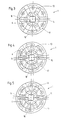
- the output shaft protrudes a central pin in a corresponding hole in the input shaft. As shown in FIGS. 3 to 5, this pin is of square design, while the bore or recess in the input shaft also is square, but with a larger edge length. Consequently can be rotated between the two shafts as far as it will go.
- Seals 7, 8, 9 are around the area of the rotary slide valve element and 10 trained.
- the input shaft is with a steering, not shown connected while the output shaft with a pinion, not shown is provided, which for example with the rack of a steering in Intervention is.
- both in End face area grooves 15, 16, 17, 18 have the control grooves form. These grooves are by means of axial bores 13, 28, 29 corresponding pressure control lines connected.
- P denotes the pressure supply area, that shown in FIG Embodiment is assigned to the annular space in the end face area.
- a The housing not shown, has a pressure supply line at this point and the pressure reaches the grooves via radially outward grooves End face intermediate area.
- T is the tank return, which via axial bores in the output shaft from the end face area is led outside.
- the housing can have a hydraulic connection for the Have tank return.
- the Output shaft has an annular constriction on it for the Tank return hole to provide an outlet.
- a and B denote the Axial bores for the pressure on the two sides of an actuator is fed. These are as axial bores in the disc-shaped Extensions trained and connected with appropriate tax grooves.
- the pressure chambers A, B, P and T are due to the seals 7,8,9 and 10 separated from each other.
- the grooves or control sinks are like this trained that they are substantially radially straight areas exhibit.
- the steering valve is shown in the neutral position.
- the Control edges of the respective grooves lie side by side.
- the input shaft is turned to the left so that the Control sinks or grooves on the A side with the grooves of the pressure feed P in Overlap.
- the B side is in with the tank return T in Coverage. The coverage is practically over the entire length of the straight edges of the grooves, so that the flow noise as far as possible be avoided.
- FIGS. 6 and 7 show a further embodiment of the invention shown.
- the input shaft 2 and the output shaft 3 have the described disk-shaped extensions 11, 12, which with the Axial bores, the control grooves, etc. are provided.
- an intermediate disk 21 used, which in the exemplary embodiment shown according to FIG an adjusting pin, in the exemplary embodiment shown according to FIG an actuator with an electrorheological fluid either with the input shaft 2 or with the output shaft 3 is rotatably connected.
- the setting pin 19 can, for example, depend on the speed of one mechanical actuator can be operated. This is also dependent on the hydraulic pressure possible.
- the electrorheological control element 20 consists essentially of an elastomer that contains chambers that are connected to a electrorheological fluid are filled.
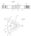
- the intermediate disk 21 has the same or different control bores 22 on the surfaces 23, 24 with the same or from each other different control edges can be provided.
- an adjusting ring 25 is in the intermediate disk 21 used which has a bore 26 for the passage of an actuator having. Due to the relative rotation of adjusting ring 25 and The intermediate disc 21 can be relative to the input shaft 2 and Adjust output shaft 3.
- FIG. 9 A functional example is shown in FIG. 9.
- the one in the output shaft arranged grooves 15 and 16 are in corresponding holes Connection, as well as the groove 17 in the input shaft. Provide the grooves the respective holes with corresponding control edges.
- a relative Twisting between the input shaft and the output shaft causes so that the grooves with their control edges overlap and a corresponding hydraulic fluid flow can be realized.
- the one in the washer arranged bores with the grooves 22a and 22b, depending on with which shaft the washer is connected, a different one Effect tax behavior. With the input shaft, i.e.
- the exemplary embodiments shown reveal different possibilities the pressure medium control and valve control, without focusing on the concrete Execution to be limited.
Landscapes
- Engineering & Computer Science (AREA)
- Chemical & Material Sciences (AREA)
- Combustion & Propulsion (AREA)
- Transportation (AREA)
- Mechanical Engineering (AREA)
- Power Steering Mechanism (AREA)
Description
- Figur 1
- eine schematische, teilgeschnittene Darstellung eines Lenkventils;
- Figur 2
- eine Darstellung gemäß Figur 1 in einer anderen radialen Position;
- Figur 3
- eine schematische Darstellung des Drehschieber-Ventilbereiches in Neutralstellung;
- Figur 4
- eine Darstellung gemäß Figur 3 in einer verdrehten Position;
- Figur 5
- eine Darstellung gemäß Figur 3 in einer anderen verdrehten Position;
- Figur 6
- eine Teildarstellung im Bereich der scheibenförmigen Erweiterungen eines Ausführungsbeispiels der Erfindung;
- Figur 7
- eine Darstellung gemäß Figur 3 eines weiteren Ausführungsbeispiels der Erfindung;
- Figur 8
- eine Darstellung einer Zwischenscheibe und
- Figur 9
- eine schematische Darstellung eines Drehschieber-Ventilbereiches mit Zwischenscheibenverwendung.
- 1
- Lenkventil
- 2
- Eingangswelle
- 3
- Ausgangswelle
- 4
- Torsionsstab
- 5
- Befestigung
- 6
- Zapfen
- 7
- Dichtung
- 8
- Dichtung
- 9
- Dichtung
- 10
- Dichtung
- 11
- scheibenförmige Erweiterung
- 12
- scheibenförmige Erweiterung
- 13
- Axialbohrung
- 14
- Einschnürung
- 15
- Nut
- 16
- Nut
- 17
- Nut
- 18
- Nut
- 19
- Stellstift
- 20
- Stellement
- 21
- Zwischenscheibe
- 22a
- Steuernuten
- 22b
- Steuernuten
- 23
- Oberfläche
- 24
- Oberfläche
- 25
- Einstellring
- 26
- Bohrung für Stellelement
- 27
- Zentrierstift
- 28
- Axialbohrung
- 29
- Axialbohrung
Claims (20)
- Drehschieber-Lenkventil (1) zur Versorgung eines Stellgliedes mit Hydraulikdruck, bestehend aus einer Eingangswelle (2), einer Ausgangswelle (3), einem zentrierenden Federelement (4) und einem Ventilelement, wobei das Ventilelement aus wenigstens zwei relativ zueinander verdrehbaren Elementen besteht, die einander zugeordnete Steuerbohrungen für Hydraulikmittelzulauf, Hydraulikmittelrücklauf und die Hydraulikmittelzuführung bzw. -rückführung zu beiden Seiten des Stellgliedes aufweisen, wobei sämtliche einander zugeordneten Steuerbohrungen des Ventilelementes ausschließlich im Bereich sich gegenüberliegender Stirnflächen der Eingangswelle (2) und der Ausgangswelle (3) ausgebildet und direkt mit gehäuseseitigen Druckmittelanschlüssen in Verbindung sind, wobei im Bereich der sich gegenüberliegenden Stirnflächen die Eingangswelle (2) und die Ausgangswelle (3) eine scheibenförmige Erweiterung (11,12) aufweisen, und wobei auf den Stirnflächen Steuersenken (15, 16, 17, 18) ausgebildet sind,
dadurch gekennzeichnet,
daß in den sich gegenüberliegenden Stirnflächen Axialbohrungen (13, 28, 29) ausgebildet sind. - Drehschieber-Lenkventil (1) nach Anspruch 1, dadurch gekennzeichnet, daß die Axialbohrungen (13, 28, 29) mit Hydraulikleitungen bildenden Bohrungen verbunden sind.
- Drehschieber-Lenkventil (1) nach Anspruch 2, dadurch gekennzeichnet, daß die Hydraulikleitungen bildenden Bohrungen Axialbohrungen sind.
- Drehschieber-Lenkventil nach Anspruch 1, dadurch gekennzeichnet, daß die Steuersenken (15, 16, 17, 18) im wesentlichen radial verlaufende, gerade Kanten aufweisen.
- Drehschieber-Lenkventil nach Anspruch 4, dadurch gekennzeichnet, daß die im wesentlichen radial verlaufenden, geraden Kanten nebeneinander liegender Steuersenken (15, 16, 17, 18) im wesentlichen zueinander parallel sind.
- Drehschieber-Lenkventil nach einem der vorhergehenden Ansprüche, dadurch gekennzeichnet, daß der relative Verdrehwinkel zwischen der Eingangswelle (2) und der Ausgangswelle (3) durch eine formschlüssige Kontur zwischen den beiden Wellen begrenzt ist.
- Drehschieber-Lenkventil nach einem der vorhergehenden Ansprüche, dadurch gekennzeichnet, daß zwischen den sich gegenüberliegenden Stirnflächen (15, 16, 17, 18) Kugeln angeordnet sind.
- Drehschieber-Lenkventil nach Anspruch 7, dadurch gekennzeichnet, daß die Kugeln federbelastet sind.
- Drehschieber-Lenkventil nach einem der Ansprüche 7 oder 8, dadurch gekennzeichnet, daß die Position der Kugeln in der Stirnflächenebene einstellbar ist.
- Drehschieber-Lenkventil nach einem der vorhergehenden Ansprüche, dadurch gekennzeichnet, daß zwischen den beiden das Ventilelement bildenden Stirnflächenbereichen wenigstens ein Steuerbohrungen (22) aufweisendes Zwischenglied (21) angeordnet ist.
- Drehschieber-Lenkventil nach Anspruch 10, dadurch gekennzeichnet, daß die Steuerbohrungen (22) an den Oberflächen (23, 24) mit Steuernuten (22a, 22b) versehen sind.
- Drehschieber-Lenkventil nach einem der Ansprüche 10 oder 11, dadurch gekennzeichnet, daß das Zwischenglied (21) mit wenigstens einer der Eingangs- (2) oder Ausgangswelle (3) verbindbar ist.
- Drehschieber-Lenkventil nach Anspruch 12, dadurch gekennzeichnet, daß die Verbindung in Abhängigkeit von Funktionsparametern herstellbar ist.
- Drehschieber-Lenkventil nach einem der Ansprüche 12 oder 13, dadurch gekennzeichnet, daß die Verbindung durch einen mechanischen Aktuator herstellbar ist.
- Drehschieber-Lenkventil nach einem der Ansprüche 12 bis 14, dadurch gekennzeichnet, daß die Verbindung unter Einsatz eines elektrorheologischen Mediums erfolgt.
- Drehschieber-Lenkventil nach einem der Ansprüche 10 bis 15, dadurch gekennzeichnet, daß das Zwischenglied (21) mittels eines Einstellringes einstellbar ist.
- Drehschieber-Lenkventil nach einem der Ansprüche 10 bis 16, dadurch gekennzeichnet, daß das Zwischenglied (21) antreibbar ist.
- Drehschieber-Lenkventil nach Anspruch 17, dadurch gekennzeichnet, daß der Antrieb durch einen Stellmotor erfolgt.
- Drehschieber-Lenkventil nach einem der Ansprüche 10 bis 18, dadurch gekennzeichnet, daß dieses mehrere Zwischenglieder (21) aufweist.
- Drehschieber-Lenkventil nach einem der Ansprüche 10 bis 19, dadurch gekennzeichnet, daß das Zwischenglied (21) eine mit Steuerbohrungen (22) versehene Scheibe ist.
Applications Claiming Priority (5)
| Application Number | Priority Date | Filing Date | Title |
|---|---|---|---|
| DE19505384 | 1995-02-17 | ||
| DE1995105384 DE19505384A1 (de) | 1995-02-17 | 1995-02-17 | Drehschieber-Lenkventil |
| DE19518637 | 1995-05-20 | ||
| DE1995118637 DE19518637C1 (de) | 1995-05-20 | 1995-05-20 | Drehschieber-Lenkventil |
| PCT/EP1996/000664 WO1996025318A1 (de) | 1995-02-17 | 1996-02-16 | Drehschieber-lenkventil |
Publications (2)
| Publication Number | Publication Date |
|---|---|
| EP0808266A1 EP0808266A1 (de) | 1997-11-26 |
| EP0808266B1 true EP0808266B1 (de) | 1998-09-30 |
Family
ID=26012531
Family Applications (1)
| Application Number | Title | Priority Date | Filing Date |
|---|---|---|---|
| EP96902279A Expired - Lifetime EP0808266B1 (de) | 1995-02-17 | 1996-02-16 | Drehschieber-lenkventil |
Country Status (5)
| Country | Link |
|---|---|
| US (1) | US5937900A (de) |
| EP (1) | EP0808266B1 (de) |
| JP (1) | JPH11500384A (de) |
| DE (1) | DE59600628D1 (de) |
| WO (1) | WO1996025318A1 (de) |
Families Citing this family (1)
| Publication number | Priority date | Publication date | Assignee | Title |
|---|---|---|---|---|
| DE19742563C2 (de) * | 1997-09-26 | 1999-10-14 | Mercedes Benz Lenkungen Gmbh | Servoventil |
Family Cites Families (18)
| Publication number | Priority date | Publication date | Assignee | Title |
|---|---|---|---|---|
| US2988059A (en) * | 1958-05-08 | 1961-06-13 | Gen Motors Corp | Fluid power steering control valve |
| JPS512179B1 (de) * | 1970-03-03 | 1976-01-23 | ||
| JPS5220530A (en) * | 1975-08-07 | 1977-02-16 | Toyoda Mach Works Ltd | Servo-valve means for power steering apparatus |
| GB1576153A (en) * | 1976-11-29 | 1980-10-01 | Bendiberica Sa | Control valve more particularly for use in a power seeringdevice |
| GB2001592B (en) * | 1977-07-29 | 1982-03-17 | Honda Motor Co Ltd | Vehicle power steering apparatus |
| FR2426818A1 (fr) * | 1978-05-26 | 1979-12-21 | Dba | Valve de distribution hydraulique, notamment pour direction assistee de vehicule automobile |
| US4204817A (en) * | 1978-12-26 | 1980-05-27 | Societe Anonyme D.B.A. | Torque-amplifying hydraulic servo-mechanism, particularly for power steering systems in motor vehicles |
| FR2448472A1 (fr) * | 1979-02-08 | 1980-09-05 | Ferodo Sa | Dispositif de direction assistee d'un vehicule |
| FR2452409A1 (fr) * | 1979-03-26 | 1980-10-24 | Ferodo Sa | Dispositif de direction assistee d'un vehicule et son procede de fabrication |
| EP0021970B1 (de) * | 1979-07-02 | 1983-11-23 | Bendiberica S.A. | Steuerventil für ein durch Druckmittel betätigtes System |
| FR2485146B1 (fr) * | 1980-06-23 | 1985-07-19 | Valeo | Dispositif d'equilibrage pour un appareil a fluide sous pression comportant deux organes mobiles l'un par rapport a l'autre et ses applications, notamment son application a une direction assistee de vehicule |
| US4421191A (en) * | 1980-09-30 | 1983-12-20 | Valeo Societe Anonyme | Power assisted steering device for a vehicle |
| FR2500397A1 (fr) * | 1981-02-23 | 1982-08-27 | Valeo | Dispositif de direction assistee d'un vehicule |
| FR2505763A1 (fr) * | 1981-05-12 | 1982-11-19 | Valeo | Dispositif de direction assistee d'un vehicule |
| ES527578A0 (es) * | 1983-11-18 | 1984-11-01 | Bendiberica Sa | Perfeccionamientos en distribuidores hidraulicos para servomecanismos |
| ES8605732A1 (es) * | 1984-10-29 | 1986-04-01 | Bendiberica Sa | Perfeccionamientos en distribuidores hidraulicos rotativos, especialmente para sistemas de direccion asistida de vehiculos automoviles |
| DE4209647A1 (de) * | 1992-03-25 | 1993-09-30 | Teves Gmbh Alfred | Drehschieberventil mit horizontal angeordneten Steueröffnungen für eine Servolenkung |
| DE4220624A1 (de) * | 1992-06-24 | 1994-01-05 | Zahnradfabrik Friedrichshafen | Drehschieberventil, insbesondere für Hilfskraftlenkungen |
-
1996
- 1996-02-16 WO PCT/EP1996/000664 patent/WO1996025318A1/de not_active Ceased
- 1996-02-16 EP EP96902279A patent/EP0808266B1/de not_active Expired - Lifetime
- 1996-02-16 DE DE59600628T patent/DE59600628D1/de not_active Expired - Fee Related
- 1996-02-16 US US08/894,323 patent/US5937900A/en not_active Expired - Fee Related
- 1996-02-16 JP JP52467496A patent/JPH11500384A/ja not_active Ceased
Also Published As
| Publication number | Publication date |
|---|---|
| EP0808266A1 (de) | 1997-11-26 |
| DE59600628D1 (de) | 1998-11-05 |
| JPH11500384A (ja) | 1999-01-12 |
| WO1996025318A1 (de) | 1996-08-22 |
| US5937900A (en) | 1999-08-17 |
Similar Documents
| Publication | Publication Date | Title |
|---|---|---|
| DE3882295T2 (de) | Servolenkungssystem. | |
| DE4323179C1 (de) | Hydraulisch unterstützte Servolenkung | |
| EP1291261A2 (de) | Lenkgetriebe | |
| DE4242441C1 (de) | Servosteuerung, insbesondere Servolenkung für Kraftfahrzeuge | |
| DE69400016T2 (de) | Hydraulische Kraftlenkvorrichtung. | |
| EP0192641B1 (de) | Zahnstangen-hilfskraftlenkung, insbesondere für kraftfahrzeuge | |
| DE3100643C2 (de) | Lenkventil für eine Hilfskraftlenkeinrichtung | |
| EP0942863B1 (de) | Dämpferventilanordnung | |
| DE4138885A1 (de) | Servolenkung, insbesondere fuer kraftfahrzeuge | |
| DE19542200C2 (de) | Servoventil | |
| DE102004015991A1 (de) | Ventil | |
| DE19518637C1 (de) | Drehschieber-Lenkventil | |
| DE4139506C2 (de) | Drehschieberventil für Servolenkungen | |
| EP0808266A1 (de) | Drehschieber-lenkventil | |
| EP1440250A1 (de) | Hydraulisch dämpfendes gummilager | |
| DE2919050A1 (de) | Hydrostatische hilfskraftlenkung, insbesondere fuer kraftfahrzeuge | |
| DE19505384A1 (de) | Drehschieber-Lenkventil | |
| DE2508268C3 (de) | Steuerkolben fur hydraulische Druckmittelfolgesteuerungen, insbesondere für ein Lenkventil einer Servolenkeinrichtung von Fahrzeugen | |
| EP1058639B1 (de) | Drehschieberventil für hilfskraftlenkungen von kraftfahrzeugen | |
| DE3827880A1 (de) | Servorsteuerung, insbesondere servolenkung fuer kraftfahrzeuge | |
| DE4209647A1 (de) | Drehschieberventil mit horizontal angeordneten Steueröffnungen für eine Servolenkung | |
| DE69014893T2 (de) | Hydraulische Kupplung. | |
| EP0941194B1 (de) | Rückwirkungsanordnung an einer servoventilanordnung | |
| WO1990003295A1 (de) | Drehschieberventil, insbesondere für hilfskraftlenkungen von kraftfahrzeugen | |
| EP0250837B1 (de) | Servosteuerung, insbesondere Servolenkung für Kraftfahrzeuge |
Legal Events
| Date | Code | Title | Description |
|---|---|---|---|
| PUAI | Public reference made under article 153(3) epc to a published international application that has entered the european phase |
Free format text: ORIGINAL CODE: 0009012 |
|
| 17P | Request for examination filed |
Effective date: 19970726 |
|
| AK | Designated contracting states |
Kind code of ref document: A1 Designated state(s): DE |
|
| GRAG | Despatch of communication of intention to grant |
Free format text: ORIGINAL CODE: EPIDOS AGRA |
|
| GRAG | Despatch of communication of intention to grant |
Free format text: ORIGINAL CODE: EPIDOS AGRA |
|
| GRAH | Despatch of communication of intention to grant a patent |
Free format text: ORIGINAL CODE: EPIDOS IGRA |
|
| 17Q | First examination report despatched |
Effective date: 19980223 |
|
| GRAH | Despatch of communication of intention to grant a patent |
Free format text: ORIGINAL CODE: EPIDOS IGRA |
|
| GRAA | (expected) grant |
Free format text: ORIGINAL CODE: 0009210 |
|
| AK | Designated contracting states |
Kind code of ref document: B1 Designated state(s): DE |
|
| REF | Corresponds to: |
Ref document number: 59600628 Country of ref document: DE Date of ref document: 19981105 |
|
| PLBE | No opposition filed within time limit |
Free format text: ORIGINAL CODE: 0009261 |
|
| STAA | Information on the status of an ep patent application or granted ep patent |
Free format text: STATUS: NO OPPOSITION FILED WITHIN TIME LIMIT |
|
| 26N | No opposition filed | ||
| PGFP | Annual fee paid to national office [announced via postgrant information from national office to epo] |
Ref country code: DE Payment date: 20060228 Year of fee payment: 11 |
|
| PG25 | Lapsed in a contracting state [announced via postgrant information from national office to epo] |
Ref country code: DE Free format text: LAPSE BECAUSE OF NON-PAYMENT OF DUE FEES Effective date: 20070901 |