EP0808084A2 - Mise hors circuit de sécurité en cas de regime asymétrique - Google Patents
Mise hors circuit de sécurité en cas de regime asymétrique Download PDFInfo
- Publication number
- EP0808084A2 EP0808084A2 EP97107206A EP97107206A EP0808084A2 EP 0808084 A2 EP0808084 A2 EP 0808084A2 EP 97107206 A EP97107206 A EP 97107206A EP 97107206 A EP97107206 A EP 97107206A EP 0808084 A2 EP0808084 A2 EP 0808084A2
- Authority
- EP
- European Patent Office
- Prior art keywords
- circuit
- voltage
- lamp
- connection point
- coupling capacitor
- Prior art date
- Legal status (The legal status is an assumption and is not a legal conclusion. Google has not performed a legal analysis and makes no representation as to the accuracy of the status listed.)
- Granted
Links
- 239000003990 capacitor Substances 0.000 claims abstract description 26
- 230000008878 coupling Effects 0.000 claims abstract description 22
- 238000010168 coupling process Methods 0.000 claims abstract description 22
- 238000005859 coupling reaction Methods 0.000 claims abstract description 22
- 238000000926 separation method Methods 0.000 claims abstract description 3
- 230000001960 triggered effect Effects 0.000 claims description 8
- 230000004913 activation Effects 0.000 claims description 2
- 230000006378 damage Effects 0.000 description 2
- 238000009499 grossing Methods 0.000 description 1
- 238000012544 monitoring process Methods 0.000 description 1
- 230000010355 oscillation Effects 0.000 description 1
- 230000003068 static effect Effects 0.000 description 1
Images

Classifications
-
- H—ELECTRICITY
- H05—ELECTRIC TECHNIQUES NOT OTHERWISE PROVIDED FOR
- H05B—ELECTRIC HEATING; ELECTRIC LIGHT SOURCES NOT OTHERWISE PROVIDED FOR; CIRCUIT ARRANGEMENTS FOR ELECTRIC LIGHT SOURCES, IN GENERAL
- H05B41/00—Circuit arrangements or apparatus for igniting or operating discharge lamps
- H05B41/14—Circuit arrangements
- H05B41/26—Circuit arrangements in which the lamp is fed by power derived from DC by means of a converter, e.g. by high-voltage DC
- H05B41/28—Circuit arrangements in which the lamp is fed by power derived from DC by means of a converter, e.g. by high-voltage DC using static converters
- H05B41/295—Circuit arrangements in which the lamp is fed by power derived from DC by means of a converter, e.g. by high-voltage DC using static converters with semiconductor devices and specially adapted for lamps with preheating electrodes, e.g. for fluorescent lamps
- H05B41/298—Arrangements for protecting lamps or circuits against abnormal operating conditions
- H05B41/2981—Arrangements for protecting lamps or circuits against abnormal operating conditions for protecting the circuit against abnormal operating conditions
- H05B41/2985—Arrangements for protecting lamps or circuits against abnormal operating conditions for protecting the circuit against abnormal operating conditions against abnormal lamp operating conditions
Definitions
- the present invention relates to an operating circuit for discharge lamps, in particular low-pressure discharge lamps.
- this also means operating circuits for a plurality of lamps, that is to say operating circuits for at least one lamp.
- Discharge lamps are operated with AC power, usually with high frequency power.
- a coupling capacitor connected in series with the lamp is used for DC decoupling.
- Circuits with safety shutdown devices which respond to the lamp voltage, that is to say the voltage drop across the discharge path of the lamp, are known.
- the invention accordingly proceeds from a circuit for AC operation of a discharge lamp via a coupling capacitor connected in series with the lamp for DC separation with a safety shutdown device, as is known in OSRAM QTEC ballasts.
- the invention is based on the technical problem of further improving the safety and operating properties of the lamp with its operating circuit.
- the problem is solved by a circuit of the type mentioned, which is characterized in that the safety shutdown device responds to a DC voltage at the coupling capacitor by means of a DC component flowing through the lamp.
- the invention thus benefits both the safety and economy, and the electromagnetic compatibility of the lamp with its operating circuit.
- a certain DC voltage at the coupling capacitor turns the safety shutdown device into a threshold value circuit triggered.
- the same threshold circuit preferably also responds to an excessive intermediate circuit voltage of the operating circuit.
- this is realized in that a fraction of the intermediate circuit voltage obtained via a voltage divider circuit is applied to the aforementioned threshold value circuit, the coupling capacitor being connected in parallel to a part of the voltage divider circuit.
- the DC voltage at the coupling capacitor can thus influence the voltages at the voltage divider circuit and thus, like the intermediate circuit voltage, also trigger the threshold value circuit.
- the lamp voltage is also monitored via the same threshold circuit, i.e. the threshold circuit is also triggered by an excessive lamp voltage.
- the threshold circuit is also triggered by an excessive lamp voltage. This can be done by applying a fraction of the lamp voltage to a portion of the voltage divider circuit through a circuit designed so that the lamp voltage fraction is superimposed on the applied fraction of the intermediate circuit voltage.
- a connection point of the voltage divider circuit can be connected via a trigger diode to a suitable point of the threshold circuit, and in such a way that the threshold circuit to both polarities of the DC voltage appeals.
- An embodiment of the circuit according to the invention provides before connecting the connection point of the trigger diode or a potential adjacent connection point via a lamp filament to the voltage divider circuit and switching a resistor between this connection point of the trigger diode or a potential adjacent connection point and one of the poles of the intermediate circuit voltage as the base potential of the safety shutdown device or another suitable base potential.
- This resistance is dimensioned such that when the lamp is removed from its socket or when the lamp filament breaks, it pulls the potential of the named connection point to the potential or as far towards the potential of the pole, so that the threshold value circuit is triggered via the trigger diode.
- the threshold circuit is a bistable multivibrator, such as a thyristor equivalent circuit with two transistors.
- a discharge lamp is often operated via a push-pull frequency generator with two transistors.
- the safety shutdown device can be constructed in such a way that after it responds via a shutdown transistor, it suppresses the activation of one of the two transistors, for example connects the base of a bipolar transistor to ground with low resistance.
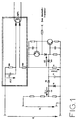
- RE1 shows an upper part RE1, RE2 of a voltage divider circuit RE1, RE2, R1 in the double-lined frame, the resistor RE1 being connected in parallel with a coupling capacitor C3 with a DC voltage UC3 dropping there in the event of a fault.
- the value of RE1 is significantly larger than the AC resistance of C3 at the operating frequency of the lamp.
- RE1 and RE2 there is also a filament of a low-pressure discharge lamp in the voltage divider circuit.
- the lamp filament is placed in the potential center of the voltage divider circuit, because the other lamp filament is generally also in the potential center of the intermediate circuit voltage in terms of DC voltage.
- the voltage Umeß falling across the resistor R1 is supplied to a connection point of a bistable multivibrator in the form of a thyristor equivalent circuit comprising two bipolar transistors when a threshold voltage UZ of a Zener diode DZ1 is exceeded.
- This flip-flop has a stable state in which both transistors are conducting and a further stable state in which both transistors are not conducting.
- the base of an npn switch-off transistor is driven via the drawn-in output signal line in such a way that it becomes conductive and the base of a transistor, also not shown, of a push-pull frequency generator operating the lamp is short-circuited to ground with low resistance.
- the flip-flop on the emitter side of the upper transistor is supplied with voltage in a suitable manner, so that a separate voltage supply is unnecessary.
- the energy for the base current of the switch-off transistor is formed there by a start capacitor for starting the frequency generator.
- the collector-emitter path of the switch-off transistor lies directly between the base of one of the transistors of the frequency generator and ground.
- the DC link voltage E of a large smoothing capacitor is applied to the voltage divider circuit C3, RE1, RE2, R1 described - as indicated on the left in FIG. 1 - in front of the push-pull frequency generator.
- the lamp voltage UL shown on the left is applied to a further voltage divider circuit (not described in any more detail), which is reduced evenly in both half-waves and is added to the capacitor C1 by the diodes D1 and D2 and the capacitor C2. Asymmetry of the lamp voltage cannot be detected here.
- This voltage is coupled into the measuring resistor R1 in a manner known to the person skilled in the art, it being superimposed on the fraction of the intermediate circuit voltage E resulting from the voltage divider circuit C3, RE1, RE2, R1. To put it clearly, in R1 there is an addition of the currents resulting from the voltages E and UL with a corresponding superposition of the voltages dropping at R1.
- circuit shown in FIG. 1 can monitor three different operating variables of the operating circuit with a single threshold circuit and can thus comprehensively detect fault states and convert them into switching off the lamp operation.
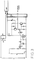
- the circuit shown in Fig. 2 corresponds to the just described except for the double-framed additional trigger diode D3 between the base of the upper transistor of the trigger circuit and a connection point between the resistor RE2 and the coupling capacitor C3 or here the lamp filament.
- the trigger diode is based on the fact that the voltage divider circuit converts only a charge or voltage UC3 at the coupling capacitor C3 opposite the intermediate circuit voltage E into a trigger signal by the Zener diode DZ1, because only then the measuring voltage Umeß is increased. If the coupling capacitor C3 is charged in the opposite direction, the potential at the upper connection point of the trigger diode D3 drops, so that this can then pull down the potential at the base of the upper trigger circuit transistor and thus trigger the trigger circuit into the conductive state.
- FIG. 3 shows the same circuit as FIG. 2, but additionally with a resistor R3 connected between the upper connection point of the trigger diode D3 and the lower pole of the intermediate circuit voltage E, here a "pulldown resistor".
- R3 connected between the upper connection point of the trigger diode D3 and the lower pole of the intermediate circuit voltage E, here a "pulldown resistor”.
- R3 connected between the upper connection point of the trigger diode D3 and the lower pole of the intermediate circuit voltage E, here a "pulldown resistor”.
- the last-described function of the circuit from FIG. 3 is particularly practical when a lamp, for example in a larger lighting system with many lamps, is to be removed. Then there is no need to switch off the entire lighting system, so that work can be carried out faster and with normal lighting.
- the applicant hereby claims protection for the invention which is independent of the rest of the disclosure, in the case of a safety shutdown device by means of a resistance between a connection point which is influenced by the lamp filament and a suitable base potential, the potential of the connection point at not to move existing power line through the coil so that the safety shutdown device responds.
Landscapes
- Circuit Arrangements For Discharge Lamps (AREA)
- Circuit Arrangement For Electric Light Sources In General (AREA)
Applications Claiming Priority (2)
| Application Number | Priority Date | Filing Date | Title |
|---|---|---|---|
| DE19619580 | 1996-05-15 | ||
| DE19619580A DE19619580A1 (de) | 1996-05-15 | 1996-05-15 | Sicherheitsabschaltung bei asymmetrischer Lampenleistung |
Publications (3)
| Publication Number | Publication Date |
|---|---|
| EP0808084A2 true EP0808084A2 (fr) | 1997-11-19 |
| EP0808084A3 EP0808084A3 (fr) | 1998-04-22 |
| EP0808084B1 EP0808084B1 (fr) | 2001-06-27 |
Family
ID=7794387
Family Applications (1)
| Application Number | Title | Priority Date | Filing Date |
|---|---|---|---|
| EP97107206A Expired - Lifetime EP0808084B1 (fr) | 1996-05-15 | 1997-04-30 | Mise hors circuit de sécurité en cas de regime asymétrique |
Country Status (4)
| Country | Link |
|---|---|
| US (1) | US5939832A (fr) |
| EP (1) | EP0808084B1 (fr) |
| CA (1) | CA2205323C (fr) |
| DE (2) | DE19619580A1 (fr) |
Cited By (2)
| Publication number | Priority date | Publication date | Assignee | Title |
|---|---|---|---|---|
| EP1189487A3 (fr) * | 2000-09-18 | 2005-01-05 | Patent-Treuhand-Gesellschaft für elektrische Glühlampen mbH | Circuit électronique pour détecter l'usure des filaments de lampes à décharge |
| EP1765042A3 (fr) * | 2005-06-20 | 2008-02-13 | Patent-Treuhand-Gesellschaft für elektrische Glühlampen mbH | Circuit d'arret pour l'onduleur d'un ballast électronique |
Families Citing this family (7)
| Publication number | Priority date | Publication date | Assignee | Title |
|---|---|---|---|---|
| DE19941437A1 (de) | 1999-08-30 | 2001-03-01 | Patent Treuhand Ges Fuer Elektrische Gluehlampen Mbh | Schaltungsanordnung zum Betrieb mindestens einer Entladungslampe |
| WO2003041457A1 (fr) * | 2001-11-07 | 2003-05-15 | Koninklijke Philips Electronics N.V. | Arrangement de circuit ballast assurant le fonctionnement d'une lampe a decharge, avec detection de la fin de duree de vie de cette lampe |
| DE10163033A1 (de) * | 2001-12-20 | 2003-07-03 | Tridonicatco Gmbh & Co Kg | Elektronisches Vorschaltgerät mit Überwachungsschaltung zum Erkennen des in einer Gasentladungslampe auftretenden Gleichrichteffekts |
| CN101060737A (zh) * | 2006-04-19 | 2007-10-24 | 皇家飞利浦电子股份有限公司 | 一种探测灯的功能状态的电路和镇流器 |
| US8482213B1 (en) | 2009-06-29 | 2013-07-09 | Panasonic Corporation | Electronic ballast with pulse detection circuit for lamp end of life and output short protection |
| US8947020B1 (en) | 2011-11-17 | 2015-02-03 | Universal Lighting Technologies, Inc. | End of life control for parallel lamp ballast |
| CN202455166U (zh) * | 2011-12-31 | 2012-09-26 | 东莞市洁德电子科技有限公司 | 感应装置、感应充电器和感应应急灯 |
Family Cites Families (8)
| Publication number | Priority date | Publication date | Assignee | Title |
|---|---|---|---|---|
| JPS57110084A (en) * | 1980-12-26 | 1982-07-08 | Toshiba Electric Equip Corp | Transistor inverter |
| US5023516A (en) * | 1988-05-10 | 1991-06-11 | Matsushita Electric Industrial Co., Ltd. | Discharge lamp operation apparatus |
| DE3925899A1 (de) * | 1989-08-04 | 1991-02-07 | Zumtobel Ag | Elektronisches vorschaltgeraet fuer gasentladungslampen |
| DE4100349C2 (de) * | 1990-01-31 | 1994-04-28 | Siemens Ag | Elektronisches Vorschaltgerät |
| US5387846A (en) * | 1991-11-27 | 1995-02-07 | Selwyn Yuen | Combination ballast for driving a fluorescent lamp or tube and ballast protection circuit |
| US5475284A (en) * | 1994-05-03 | 1995-12-12 | Osram Sylvania Inc. | Ballast containing circuit for measuring increase in DC voltage component |
| US5528147A (en) * | 1994-06-30 | 1996-06-18 | Motorola Lighting, Inc. | Apparatus for detecting gas discharge lamp faults |
| US5574335A (en) * | 1994-08-02 | 1996-11-12 | Osram Sylvania Inc. | Ballast containing protection circuit for detecting rectification of arc discharge lamp |
-
1996
- 1996-05-15 DE DE19619580A patent/DE19619580A1/de not_active Withdrawn
-
1997
- 1997-04-30 DE DE59703889T patent/DE59703889D1/de not_active Expired - Lifetime
- 1997-04-30 EP EP97107206A patent/EP0808084B1/fr not_active Expired - Lifetime
- 1997-05-09 US US08/853,996 patent/US5939832A/en not_active Expired - Lifetime
- 1997-05-14 CA CA002205323A patent/CA2205323C/fr not_active Expired - Fee Related
Cited By (2)
| Publication number | Priority date | Publication date | Assignee | Title |
|---|---|---|---|---|
| EP1189487A3 (fr) * | 2000-09-18 | 2005-01-05 | Patent-Treuhand-Gesellschaft für elektrische Glühlampen mbH | Circuit électronique pour détecter l'usure des filaments de lampes à décharge |
| EP1765042A3 (fr) * | 2005-06-20 | 2008-02-13 | Patent-Treuhand-Gesellschaft für elektrische Glühlampen mbH | Circuit d'arret pour l'onduleur d'un ballast électronique |
Also Published As
| Publication number | Publication date |
|---|---|
| CA2205323A1 (fr) | 1997-11-15 |
| US5939832A (en) | 1999-08-17 |
| CA2205323C (fr) | 2005-03-22 |
| EP0808084A3 (fr) | 1998-04-22 |
| DE59703889D1 (de) | 2001-08-02 |
| DE19619580A1 (de) | 1997-11-20 |
| EP0808084B1 (fr) | 2001-06-27 |
Similar Documents
| Publication | Publication Date | Title |
|---|---|---|
| DE4002334C2 (de) | Schaltung zum Betreiben einer elektrischen Entladelampe in einem Kraftfahrzeug | |
| DE2817142A1 (de) | Ueberwachungssystem | |
| EP1233657B1 (fr) | Circuit de protection pour tube fluorescent | |
| EP2564671B1 (fr) | Circuit d'interface à résistance diélectrique | |
| DE60017709T2 (de) | Anordnung zur Fernüberwachung von Led Leuchten | |
| EP0808084B1 (fr) | Mise hors circuit de sécurité en cas de regime asymétrique | |
| DE4425859A1 (de) | Schaltungsanordnung zum Betrieb einer oder mehrerer Niederdruckentladungslampen | |
| DE69410510T2 (de) | Schutzschaltung für eine Leistungsversorgung einer Beleuchtungsrohre | |
| DE3711814C2 (de) | Elektronisches Vorschaltgerät zum Betrieb von Leuchtstofflampen | |
| EP0825806A1 (fr) | Circuit pour alimenter des lampes à incandescence | |
| EP0572585B1 (fr) | Dispositif utilise pour faire fonctionner une lampe a decharge | |
| DE102018107500B4 (de) | Lampentreiber für eine LED Lampe und LED Lampe zum Einsetzen in eine Leuchtstofflampenleuchte | |
| DE69803395T2 (de) | Schaltung zur synchronisierung der zündung von entladungslampen mit elektronischem vorschaltgerät | |
| CH664048A5 (de) | Schutzschaltung fuer eine wechselrichterschaltung. | |
| EP0682464A1 (fr) | Circuit pour alimenter des lampes électriques | |
| EP0648068B1 (fr) | Circuit d'alimentation de lampes électriques | |
| EP0871347A1 (fr) | Ballast à réamorçage automatique | |
| EP0881864B1 (fr) | Circuit pour l'alimentation des lampes incandescentes | |
| EP0809923B1 (fr) | Circuit destine au fonctionnement d'une lampe a decharge | |
| EP0314178B1 (fr) | Circuit d'amorçage pour lampes à haute pression et à vapeur métallique | |
| EP0276460A1 (fr) | Disposition de circuit pour mettre en oeuvre une lampe à décharge basse pression | |
| WO2011135097A1 (fr) | Circuit d'interface et procédé pour influencer la pente d'un signal d'excitation | |
| EP1086477B1 (fr) | Circuit d'entree pour signaux de courant alternatif a intensite relativement elevee a surveiller | |
| EP1583403A1 (fr) | Ballast pour au moins une lampe | |
| EP2140735B1 (fr) | Ensemble circuit servant à amorcer et à faire fonctionner au moins une lampe à décharge |
Legal Events
| Date | Code | Title | Description |
|---|---|---|---|
| PUAI | Public reference made under article 153(3) epc to a published international application that has entered the european phase |
Free format text: ORIGINAL CODE: 0009012 |
|
| AK | Designated contracting states |
Kind code of ref document: A2 Designated state(s): BE DE FR GB IT NL |
|
| PUAL | Search report despatched |
Free format text: ORIGINAL CODE: 0009013 |
|
| AK | Designated contracting states |
Kind code of ref document: A3 Designated state(s): BE DE FR GB IT NL |
|
| 17P | Request for examination filed |
Effective date: 19980519 |
|
| 17Q | First examination report despatched |
Effective date: 19980611 |
|
| RIC1 | Information provided on ipc code assigned before grant |
Free format text: 7H 05B 41/295 A |
|
| GRAG | Despatch of communication of intention to grant |
Free format text: ORIGINAL CODE: EPIDOS AGRA |
|
| GRAG | Despatch of communication of intention to grant |
Free format text: ORIGINAL CODE: EPIDOS AGRA |
|
| GRAH | Despatch of communication of intention to grant a patent |
Free format text: ORIGINAL CODE: EPIDOS IGRA |
|
| GRAH | Despatch of communication of intention to grant a patent |
Free format text: ORIGINAL CODE: EPIDOS IGRA |
|
| GRAA | (expected) grant |
Free format text: ORIGINAL CODE: 0009210 |
|
| AK | Designated contracting states |
Kind code of ref document: B1 Designated state(s): BE DE FR GB IT NL |
|
| REF | Corresponds to: |
Ref document number: 59703889 Country of ref document: DE Date of ref document: 20010802 |
|
| ITF | It: translation for a ep patent filed | ||
| GBT | Gb: translation of ep patent filed (gb section 77(6)(a)/1977) |
Effective date: 20010910 |
|
| ET | Fr: translation filed | ||
| REG | Reference to a national code |
Ref country code: GB Ref legal event code: IF02 |
|
| PLBE | No opposition filed within time limit |
Free format text: ORIGINAL CODE: 0009261 |
|
| STAA | Information on the status of an ep patent application or granted ep patent |
Free format text: STATUS: NO OPPOSITION FILED WITHIN TIME LIMIT |
|
| 26N | No opposition filed | ||
| PGFP | Annual fee paid to national office [announced via postgrant information from national office to epo] |
Ref country code: NL Payment date: 20060404 Year of fee payment: 10 |
|
| PGFP | Annual fee paid to national office [announced via postgrant information from national office to epo] |
Ref country code: GB Payment date: 20060411 Year of fee payment: 10 |
|
| PGFP | Annual fee paid to national office [announced via postgrant information from national office to epo] |
Ref country code: BE Payment date: 20060419 Year of fee payment: 10 |
|
| PGFP | Annual fee paid to national office [announced via postgrant information from national office to epo] |
Ref country code: FR Payment date: 20060425 Year of fee payment: 10 |
|
| PGFP | Annual fee paid to national office [announced via postgrant information from national office to epo] |
Ref country code: IT Payment date: 20060430 Year of fee payment: 10 |
|
| GBPC | Gb: european patent ceased through non-payment of renewal fee |
Effective date: 20070430 |
|
| BERE | Be: lapsed |
Owner name: *PATENT-TREUHAND-G.- FUR ELEKTRISCHE GLUHLAMPEN M. Effective date: 20070430 |
|
| NLV4 | Nl: lapsed or anulled due to non-payment of the annual fee |
Effective date: 20071101 |
|
| PG25 | Lapsed in a contracting state [announced via postgrant information from national office to epo] |
Ref country code: NL Free format text: LAPSE BECAUSE OF NON-PAYMENT OF DUE FEES Effective date: 20071101 |
|
| PG25 | Lapsed in a contracting state [announced via postgrant information from national office to epo] |
Ref country code: BE Free format text: LAPSE BECAUSE OF NON-PAYMENT OF DUE FEES Effective date: 20070430 |
|
| PG25 | Lapsed in a contracting state [announced via postgrant information from national office to epo] |
Ref country code: GB Free format text: LAPSE BECAUSE OF NON-PAYMENT OF DUE FEES Effective date: 20070430 |
|
| PG25 | Lapsed in a contracting state [announced via postgrant information from national office to epo] |
Ref country code: FR Free format text: LAPSE BECAUSE OF NON-PAYMENT OF DUE FEES Effective date: 20070430 |
|
| PG25 | Lapsed in a contracting state [announced via postgrant information from national office to epo] |
Ref country code: IT Free format text: LAPSE BECAUSE OF NON-PAYMENT OF DUE FEES Effective date: 20070430 |
|
| PGFP | Annual fee paid to national office [announced via postgrant information from national office to epo] |
Ref country code: DE Payment date: 20110620 Year of fee payment: 15 |
|
| REG | Reference to a national code |
Ref country code: DE Ref legal event code: R119 Ref document number: 59703889 Country of ref document: DE Effective date: 20121101 |
|
| PG25 | Lapsed in a contracting state [announced via postgrant information from national office to epo] |
Ref country code: DE Free format text: LAPSE BECAUSE OF NON-PAYMENT OF DUE FEES Effective date: 20121101 |