EP0808077B1 - Elektrodenstruktur für hochtemperaturgeheizten Körper - Google Patents
Elektrodenstruktur für hochtemperaturgeheizten Körper Download PDFInfo
- Publication number
- EP0808077B1 EP0808077B1 EP97107795A EP97107795A EP0808077B1 EP 0808077 B1 EP0808077 B1 EP 0808077B1 EP 97107795 A EP97107795 A EP 97107795A EP 97107795 A EP97107795 A EP 97107795A EP 0808077 B1 EP0808077 B1 EP 0808077B1
- Authority
- EP
- European Patent Office
- Prior art keywords
- temperature side
- side electrode
- high temperature
- electrode
- low temperature
- Prior art date
- Legal status (The legal status is an assumption and is not a legal conclusion. Google has not performed a legal analysis and makes no representation as to the accuracy of the status listed.)
- Expired - Lifetime
Links
Images


Classifications
-
- F—MECHANICAL ENGINEERING; LIGHTING; HEATING; WEAPONS; BLASTING
- F01—MACHINES OR ENGINES IN GENERAL; ENGINE PLANTS IN GENERAL; STEAM ENGINES
- F01N—GAS-FLOW SILENCERS OR EXHAUST APPARATUS FOR MACHINES OR ENGINES IN GENERAL; GAS-FLOW SILENCERS OR EXHAUST APPARATUS FOR INTERNAL-COMBUSTION ENGINES
- F01N3/00—Exhaust or silencing apparatus having means for purifying, rendering innocuous, or otherwise treating exhaust
- F01N3/08—Exhaust or silencing apparatus having means for purifying, rendering innocuous, or otherwise treating exhaust for rendering innocuous
- F01N3/10—Exhaust or silencing apparatus having means for purifying, rendering innocuous, or otherwise treating exhaust for rendering innocuous by thermal or catalytic conversion of noxious components of exhaust
- F01N3/18—Exhaust or silencing apparatus having means for purifying, rendering innocuous, or otherwise treating exhaust for rendering innocuous by thermal or catalytic conversion of noxious components of exhaust characterised by methods of operation; Control
- F01N3/20—Exhaust or silencing apparatus having means for purifying, rendering innocuous, or otherwise treating exhaust for rendering innocuous by thermal or catalytic conversion of noxious components of exhaust characterised by methods of operation; Control specially adapted for catalytic conversion
- F01N3/2006—Periodically heating or cooling catalytic reactors, e.g. at cold starting or overheating
- F01N3/2013—Periodically heating or cooling catalytic reactors, e.g. at cold starting or overheating using electric or magnetic heating means
-
- F—MECHANICAL ENGINEERING; LIGHTING; HEATING; WEAPONS; BLASTING
- F01—MACHINES OR ENGINES IN GENERAL; ENGINE PLANTS IN GENERAL; STEAM ENGINES
- F01N—GAS-FLOW SILENCERS OR EXHAUST APPARATUS FOR MACHINES OR ENGINES IN GENERAL; GAS-FLOW SILENCERS OR EXHAUST APPARATUS FOR INTERNAL-COMBUSTION ENGINES
- F01N13/00—Exhaust or silencing apparatus characterised by constructional features
- F01N13/009—Exhaust or silencing apparatus characterised by constructional features having two or more separate purifying devices arranged in series
- F01N13/0097—Exhaust or silencing apparatus characterised by constructional features having two or more separate purifying devices arranged in series the purifying devices are arranged in a single housing
-
- F—MECHANICAL ENGINEERING; LIGHTING; HEATING; WEAPONS; BLASTING
- F01—MACHINES OR ENGINES IN GENERAL; ENGINE PLANTS IN GENERAL; STEAM ENGINES
- F01N—GAS-FLOW SILENCERS OR EXHAUST APPARATUS FOR MACHINES OR ENGINES IN GENERAL; GAS-FLOW SILENCERS OR EXHAUST APPARATUS FOR INTERNAL-COMBUSTION ENGINES
- F01N3/00—Exhaust or silencing apparatus having means for purifying, rendering innocuous, or otherwise treating exhaust
- F01N3/08—Exhaust or silencing apparatus having means for purifying, rendering innocuous, or otherwise treating exhaust for rendering innocuous
- F01N3/10—Exhaust or silencing apparatus having means for purifying, rendering innocuous, or otherwise treating exhaust for rendering innocuous by thermal or catalytic conversion of noxious components of exhaust
- F01N3/18—Exhaust or silencing apparatus having means for purifying, rendering innocuous, or otherwise treating exhaust for rendering innocuous by thermal or catalytic conversion of noxious components of exhaust characterised by methods of operation; Control
- F01N3/20—Exhaust or silencing apparatus having means for purifying, rendering innocuous, or otherwise treating exhaust for rendering innocuous by thermal or catalytic conversion of noxious components of exhaust characterised by methods of operation; Control specially adapted for catalytic conversion
- F01N3/2006—Periodically heating or cooling catalytic reactors, e.g. at cold starting or overheating
- F01N3/2013—Periodically heating or cooling catalytic reactors, e.g. at cold starting or overheating using electric or magnetic heating means
- F01N3/2026—Periodically heating or cooling catalytic reactors, e.g. at cold starting or overheating using electric or magnetic heating means directly electrifying the catalyst substrate, i.e. heating the electrically conductive catalyst substrate by joule effect
-
- H—ELECTRICITY
- H05—ELECTRIC TECHNIQUES NOT OTHERWISE PROVIDED FOR
- H05B—ELECTRIC HEATING; ELECTRIC LIGHT SOURCES NOT OTHERWISE PROVIDED FOR; CIRCUIT ARRANGEMENTS FOR ELECTRIC LIGHT SOURCES, IN GENERAL
- H05B3/00—Ohmic-resistance heating
- H05B3/02—Details
- H05B3/06—Heater elements structurally combined with coupling elements or holders
- H05B3/08—Heater elements structurally combined with coupling elements or holders having electric connections specially adapted for high temperatures
-
- Y—GENERAL TAGGING OF NEW TECHNOLOGICAL DEVELOPMENTS; GENERAL TAGGING OF CROSS-SECTIONAL TECHNOLOGIES SPANNING OVER SEVERAL SECTIONS OF THE IPC; TECHNICAL SUBJECTS COVERED BY FORMER USPC CROSS-REFERENCE ART COLLECTIONS [XRACs] AND DIGESTS
- Y02—TECHNOLOGIES OR APPLICATIONS FOR MITIGATION OR ADAPTATION AGAINST CLIMATE CHANGE
- Y02T—CLIMATE CHANGE MITIGATION TECHNOLOGIES RELATED TO TRANSPORTATION
- Y02T10/00—Road transport of goods or passengers
- Y02T10/10—Internal combustion engine [ICE] based vehicles
- Y02T10/12—Improving ICE efficiencies
Definitions
- This invention relates to an electrode for connecting an electric wire to a heated body which is heated to a high temperature. More specifically, this invention relates to an electrode structure of an electrically heated-type catalyst device.
- An electrically heated-type catalyst device which is heated by electricity to quickly activate a catalyst after the start from a cold state is disclosed, for example, in Japanese Unexamined Patent Publication (Kokai) No. 6-108831.
- a solid stud bolt is connected to a catalyst while the other end is extended to the outside of an exhaust pipe and is connected to an external wire.
- a copper cable copper wire is used in most cases as the external electric wire.
- the junction between the stud bolt and the external electric wire exists in the proximity of the catalyst, the junction is likely to be heated by the catalyst through the stud bolt and attains a high temperature, or the junction on the stud bolt side is likely to undergo high temperature oxidation and invites conduction failure. Further, the external electric wire, too, attains a high temperature, so that the problems such as the material change of the electric wire itself or deterioration of a covering material occur.
- Document EP 0 669 453 A1 discloses an electrically heated catalytic converter with a substrate for a catalyst, a rod-like metal electrode connected to the substrate and a casing accommodating the substrate.
- the document discloses possibilities of reducing the temperature of the electrode at the portion connected to a electric supply cable. This object is implemented by using a electrode formed as a hollow pipe, since the heat mass of the hollow pipe electrode is very small compared with a solid metal rod electrode.
- Another possibility of reducing the temperature of the electrode is to distant the electrode at the penetration portion, where the electrode is penetrating the casing, by forming a flange on an outer suface of the electrode and holding that flange by heat isolating members.
- the object of the present invention is to aim at lowering the temperature at the junction between the lead-out electrode of the electrically heated-type catalyst device with a simple structure and without increasing the resistance value.
- an electrode for connecting an external electric wire to a heated body heated to a high temperature which comprises a high temperature side electrode made of a conductor and connected to the heated body; and a low temperature side electrode connected at one of the end portions thereof with the high temperature side electrode and having the other end portion thereof connected to the external electric wire; wherein the low temperature side electrode is produced by covering a conductor disposed at the center with a covering material through an insulator, and the conductor of the low temperature side electrode is made of a material having a lower conduction resistivity than that of the conductor of the high temperature side electrode.
- Fig. 1 is a sectional view of a catalyst device interposed into an intermediate part of an exhaust pipe of a car.
- Reference numeral 100 denotes a catalyst container as a whole.
- This catalyst container 100 comprises a catalyst container first portion 101, a container second portion 102, a container third portion 103 and a container fourth portion 104 that are coupled by welding.
- a flange 101a is fitted to the outside of the catalyst container first portion 101 so as to connect an upstream side exhaust pipe (not shown), and a flange 104a is fitted to the outside of the container fourth portion 104 so as to connect a downstream side exhaust pipe (not shown).
- the electric heating catalyst 1 includes a support made of a metal and is held in place by a buffer material 105 made of a conductive material, for flexibly supporting the catalyst in a circumferential direction, a stopper 107 made of an insulating material, for preventing the catalyst from being moved in the downstream direction by a gas pressure, and a holding member 106 for holding this stopper 107.
- a solid, rod-like first high temperature side electrode 2 made of a heat-resistant metal such as a stainless steel is fitted to the center portion of the electric heating catalyst 1, and a sheet-like second high temperature side electrode 3 extending toward the outer peripheral side is fitted to the end portion of the first high temperature side electrode 2 on its downstream side.
- This second high temperature side electrode 3 is bent into the shape as shown in Fig. 1 so that it can absorb shrinkage due to the temperature change.
- a third high temperature side electrode 4 is fitted to the other end of the second high temperature side electrode 3, and extends outside through an opening 102a bored in the catalyst container second portion 102.
- a conductor 6 made of a conductive material is disposed at a center portion, and a low temperature side electrode 5 covered with a metal pipe 8 through an insulating material 7 made of MgO (magnesium oxide) is welded round the opening 102a formed in the catalyst container second portion 102 through its metal pipe 8.
- MgO manganesium oxide
- the outer distal end portion of the third high temperature side electrode 4 is caulked or welded to the distal end portion of the conductor 6 of the low temperature side electrode 5 on the side of the catalyst container 100.
- a scatter preventive member 9 is packed to the distal end portion of the low temperature side electrode 5 on the side of the catalyst container 100 so as to prevent the insulating material 7 from breaking and scattering into the catalyst container 100, and the distal end portion of the metal pipe 8 is deformed lest this scatter preventive member 9 falls off into the catalyst container 100.
- the external electric wire (not shown) is connected to the other end portion of the conductor 6 of the low temperature side electrode 5. Therefore, the low temperature side electrode 5 has a sufficient length lest the temperature of the connection portion becomes too high. For this reason, the conductor 6 of the low temperature side electrode 5 comprises a twisted wire made of a material having a small conduction resistance such as Ni (nickel), whereas the third high temperature side electrode 4 is made of a stainless steel having a high conduction resistance.
- the distal end portion of the metal pipe 8 is deformed lest the scatter preventive member 10 packed into it falls off, in the same way as the distal end portion of the catalyst container 100, but this arrangement is not necessary if the insulating material 7 at this portion is not broken and scatters.
- the low temperature side electrode 5 which is thus elongated is perpendicularly extended with respect to the outer surface of the catalyst container second portion 102, the second portion 102 is more likely to interfere with other components and mountability drops. Therefore, the low temperature side electrode 5 is folded and bent in such a manner as to extend along the catalyst container 100 as shown in the drawing.
- the thickness of the curved portion of the metal pipe 8 is greater than that of its straight line portion so as to avoid the occurrence of local cracking and the drop in the thickness at the time of bending and folding work.
- the thickness of the weld portion of the metal pipe 8 to the periphery of the opening 102a formed in the catalyst container second portion 102 is further greater than the thickness of its curved portion so as to prevent deformation and to improve durability because the low temperature side electrode 5 is supported as a whole by this weld portion.
- the thickness of the weld portion is t1
- the thickness of the curved portion is t2
- the thickness of the portion closer to the external electrode than the curved portion is t3
- the relation t1 > t2 > t3 is satisfied.
- Fig. 2 is a partial enlarged view of Fig. 1 so that the difference of the thickness can be more easily understood.
- the low temperature side electrode 5 is made of a material having a smaller conduction resistance than the third high temperature side electrode 4 as described above, the length of the low temperature side electrode 5 is increased so that the temperature at the connection portion with the external electric wire can be sufficiently lowered without increasing the conduction resistance. Therefore, the present invention is free from the problems of the prior art in that the temperature of the external electric wire at the connection portion rises, the material changes and conduction defect develops. Because the temperature at the connection portion of the external electric wire can be sufficiently lowered, an ordinary electric wire such as a vinyl-coated copper wire can be used for the external electric wire.
- the low temperature side electrode 5 When extended, the low temperature side electrode 5 is so bent and folded as to extend along the catalyst container 100 and is less likely to interfere with other components. Therefore, mountability is not deteriorated.
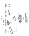
- the electrode having the construction described above is produced by the following production steps.
- Fig. 3 shows the production steps (1) to (8) among the steps described above.
- the insulating material 7 under the material component state before machining is not a unitary product but is a plurality of components cut into a suitable length.
- the electrode is produced as described above, particularly when the conductor of the low temperature side conductor is disposed in the insulating material, the positioning work is not necessary, but it can be positioned accurately and within a short time without requiring skill.
- the present invention can lower the temperature of the junction of the external electric wire connected to the heated body which is heated to a high temperature, without increasing the conduction resistance.
- An electrode for connecting an external electric wire to a heated body heated to a high temperature An electrode for connecting an external electric wire to a heated body heated to a high temperature.
- the electrode of this invention comprises a high temperature side electrode made of a conductor connected to the heated body, and a low temperature side electrode connected at one of the ends thereof to the high temperature side electrode and at the other end thereof to the external electric wire.
- the low temperature side electrode is formed by covering a conductor disposed at the center by a covering material through an insulating material, and the conductor of the low temperature side electrode is made of a material having a smaller conduction resistance than that of the conductor of the high temperature side electrode.
- the conductor of the low temperature side electrode is made of the material having a smaller conduction resistance than that of the conductor of the high temperature side electrode, the increase of the resistance value can be restricted even when the conductor is extended so that the temperature of the connecting portion with the external electric wire becomes lower.
Landscapes
- Engineering & Computer Science (AREA)
- Chemical & Material Sciences (AREA)
- Chemical Kinetics & Catalysis (AREA)
- Combustion & Propulsion (AREA)
- Mechanical Engineering (AREA)
- General Engineering & Computer Science (AREA)
- Health & Medical Sciences (AREA)
- Toxicology (AREA)
- Exhaust Gas After Treatment (AREA)
- Resistance Heating (AREA)
- Exhaust Gas Treatment By Means Of Catalyst (AREA)
Claims (12)
- Ein Elektrodenaufbau zum Verbinden eines externen elektrischen Drahts mit einen erhitzten Körper, der auf eine hohe Temperatur aufgeheizt wird, gekennzeichnet durch
eine hochtemperaturseitige Elektrode (2, 3, 4), die aus einem Stromleiter hergestellt ist, der mit dem erhitzten Körper verbunden ist; und
eine niedertemperaturseitige Elektrode (5), von der ein Endabschnitt mit der hochtemperaturseitigen Elektrode (2, 3, 4) verbunden ist und von der der andere Endabschnitt mit dem externen elektrischen Draht verbunden ist; wobei
die niedertemperaturseitige Elektrode (5) ausgebildet wird, indem ein mittig angeordneter Stromleiter (6) mit einem Abdeckmaterial über ein Isolationsmaterial abgedeckt wird; und
der Stromleiter (6) der niedertemperaturseitigen Elektrode (5) aus einem Material hergestellt ist, das einen kleineren Leitungswiderstand hat als der des Stromleiters der hochtemperaturseitigen Elektrode (2, 3, 4). - Elektrodenaufbau gemäß Anspruch 1, wobei der erhitzte Körper ein Katalysator (1) ist, der innerhalb eines Abgaskanals eines Verbrennungsmotors angeordnet ist, wobei die hochtemperaturseitige Elektrode (2, 3, 4), mit dem Katalysator (1) verbunden ist und innerhalb dem Abgaskanal angeordnet ist, und wobei die niedertemperaturseitige Elektrode (5) außerhalb des Abgaskanals angeordnet ist.
- Elektrodenaufbau gemäß Anspruch 2, wobei sich die niedertemperaturseitige Elektrode (5) zur Verbindung mit dem externen elektrischen Draht entlang der Außenwand des Abgaskanals über einen gekrümmten Abschnitt erstreckt und die Dicke des Abdeckmaterials an dem gekrümmten Abschnitt größer als die Dicke des Abdeckmaterials an dem Abschnitt entlang der Außenwand ist.
- Elektrodenaufbau gemäß Anspruch 2, wobei die niedertemperaturseitige Elektrode (5) als Gesamtheit unterstützt wird, wenn das Abdeckmaterial der niedertemperaturseitigen Elektrode (5) an die Außenwand des Abgaskanals geschweißt ist, und die Dicke des Abdeckmaterials an dem geschweißten Abschnitt größer als die Dicke des Abdeckmaterials an anderen Abschnitten ist.
- Elektrodenaufbau gemäß Anspruch 2, wobei die hochtemperaturseitige Elektrode (2, 3, 4) des Weiteren eine erste hochtemperaturseitige Elektrode (2), eine zweite hochtemperaturseitige Elektrode (3) und eine dritte hochtemperaturseitige Elektrode (4) hat;
wobei die erste hochtemperaturseitige Elektrode (2) direkt mit einem Ende mit dem Katalysator (1) verbunden ist und wobei deren anderes Ende mit der zweiten hochtemperaturseitigen Elektrode (3) verbunden ist;
wobei die zweite hochtemperaturseitige Elektrode (3) solch eine Form hat, dass sie temperaturveränderungsbedingtes Schrumpfen absorbiert und von der ein Ende mit der ersten hochtemperaturseitigen Elektrode (2) und von der das andere Ende mit der dritten hochtemperaturseitigen Elektrode (4) verbunden ist; und
wobei die dritte hochtemperaturseitige Elektrode (4) so angeordnet ist, dass sie durch die Wand des Katalysatorbehälters (100) dringt, der einen Teil des Abgaskanals bildet, und von der ein Ende mit der zweiten hochtemperaturseitigen Elektrode (3) und von der das andere Ende mit der niedertemperaturseitigen Elektrode (5) verbunden ist. - Elektrodenaufbau gemäß Anspruch 5, wobei die dritte hochtemperaturseitige Elektrode (4) und die niedertemperaturseitige Elektrode (5) mittels Verstemmen verbunden sind.
- Elektrodenaufbau gemäß Anspruch 5, wobei die dritte hochtemperaturseitige Elektrode (4) und die niedertemperaturseitige Elektrode (5) durch Schweißen verbunden sind.
- Elektrodenaufbau gemäß Anspruch 1, wobei die hochtemperaturseitige Elektrode (2, 3, 4) aus einem Edelstahl hergestellt ist.
- Elektrodenaufbau gemäß Anspruch 1, wobei der Stromleiter (6) der niedertemperaturseitigen Elektrode (5) aus einem verdrillten Draht aus Nickel hergestellt ist.
- Elektrodenaufbau gemäß Anspruch 1, wobei das Isolationsmaterial der niedertemperaturseitigen Elektrode (5) Magnesiumoxid ist.
- Elektrodenaufbau gemäß Anspruch 1, wobei das Abdeckmaterial der niedertemperaturseitigen Elektrode (5) ein Rohr (8) aus Metall ist.
- Elektrodenaufbau gemäß Anspruch 1, wobei die niedertemperaturseitige Elektrode (5) hergestellt wird, indem der Stromleiter (6) in das Isolationsmaterial gepasst wird, das im Voraus in einer hohlen rohrförmigen Form ausgebildet wird, dann die erhaltene Baugruppe in das Abdeckmaterial eingefügt wird, das im Voraus in einer hohlen rohrförmigen Form ausgebildet ist, und dann die resultierende Baugruppe einem Gesamtreduktionsrollen mittels Gesenkformen unterworfen wird.
Applications Claiming Priority (3)
| Application Number | Priority Date | Filing Date | Title |
|---|---|---|---|
| JP11922096A JP3702531B2 (ja) | 1996-05-14 | 1996-05-14 | 高温被加熱体の電極の構造とその製造方法 |
| JP11922096 | 1996-05-14 | ||
| JP119220/96 | 1996-05-14 |
Publications (3)
| Publication Number | Publication Date |
|---|---|
| EP0808077A2 EP0808077A2 (de) | 1997-11-19 |
| EP0808077A3 EP0808077A3 (de) | 1998-09-16 |
| EP0808077B1 true EP0808077B1 (de) | 2005-01-26 |
Family
ID=14755938
Family Applications (1)
| Application Number | Title | Priority Date | Filing Date |
|---|---|---|---|
| EP97107795A Expired - Lifetime EP0808077B1 (de) | 1996-05-14 | 1997-05-13 | Elektrodenstruktur für hochtemperaturgeheizten Körper |
Country Status (4)
| Country | Link |
|---|---|
| US (1) | US6060699A (de) |
| EP (1) | EP0808077B1 (de) |
| JP (1) | JP3702531B2 (de) |
| DE (1) | DE69732319T2 (de) |
Families Citing this family (14)
| Publication number | Priority date | Publication date | Assignee | Title |
|---|---|---|---|---|
| DE10102671C2 (de) * | 2001-01-17 | 2003-12-24 | Eichenauer Heizelemente Gmbh | Elektrische Heizung für ein Kraftfahrzeug |
| DE10208103A1 (de) * | 2002-02-26 | 2003-09-11 | Beru Ag | Elektrische Luftheizungsvorrichtung insbesondere für ein Kraftfahrzeug |
| US20110072805A1 (en) * | 2009-09-25 | 2011-03-31 | International Engine Intellectual Property Company Llc | Electrically heated diesel oxidation catalyst |
| JP5413398B2 (ja) | 2011-04-08 | 2014-02-12 | トヨタ自動車株式会社 | 触媒コンバータ装置 |
| DE202013007140U1 (de) * | 2013-08-09 | 2013-08-27 | Abb Technology Ag | Magnetisch-induktiver Durchflussmesser |
| JP6131980B2 (ja) * | 2015-03-27 | 2017-05-24 | トヨタ自動車株式会社 | 電気加熱式触媒コンバーター |
| US9848527B2 (en) * | 2015-09-30 | 2017-12-26 | Deere & Company | Furrow following device |
| JP6420803B2 (ja) * | 2016-09-23 | 2018-11-07 | 本田技研工業株式会社 | 排気ガス浄化触媒加熱装置 |
| DE102019210368B4 (de) * | 2019-07-12 | 2024-05-08 | Vitesco Technologies GmbH | Elektrische Stromdurchführung |
| DE102019218477B4 (de) | 2019-11-28 | 2022-01-05 | Heraeus Deutschland GmbH & Co. KG | Mikro-Lead für direktionale Stimulation |
| DE102020210889A1 (de) * | 2020-08-28 | 2022-03-03 | Vitesco Technologies GmbH | Elektrische Durchführung |
| DE102021209264B3 (de) * | 2021-08-24 | 2023-01-05 | Vitesco Technologies GmbH | Elektrische Durchführung mit poröser Keramikschicht und einem Porenfüller |
| DE102022207488A1 (de) * | 2022-07-21 | 2024-02-01 | Vitesco Technologies GmbH | Segmentierte elektrische Durchführung |
| DE102023109630A1 (de) * | 2023-04-17 | 2024-10-17 | Daimler Truck AG | Durchführung für einen elektrischen Leiter |
Citations (1)
| Publication number | Priority date | Publication date | Assignee | Title |
|---|---|---|---|---|
| EP0532138A2 (de) * | 1991-09-13 | 1993-03-17 | W.R. Grace & Co.-Conn. | Elektrode-Durchführung |
Family Cites Families (11)
| Publication number | Priority date | Publication date | Assignee | Title |
|---|---|---|---|---|
| JPS5142145A (ja) * | 1974-10-05 | 1976-04-09 | Riken Piston Ring Ind Co Ltd | Denkiteikoroyoshijisochi |
| US5053603A (en) * | 1989-03-30 | 1991-10-01 | Donaldson Company, Inc. | Electrical resistance heater |
| JPH04295475A (ja) * | 1991-03-22 | 1992-10-20 | Japan Tobacco Inc | 2’,3’−ジデオキシ−2’,3’− ジデヒドロヌクレオシド類の製法 |
| DE9205259U1 (de) * | 1992-04-15 | 1992-08-27 | Fritz Eichenauer GmbH + Co. KG Fabrik elektrischer Spezialartikel, 6729 Hatzenbühl | Partikelrußfilter |
| DE69308794T2 (de) * | 1992-12-21 | 1997-10-23 | Nippon Soken | Elektrisch beheizbarer Katalysator |
| DE4303581A1 (de) * | 1993-02-08 | 1994-08-11 | Emitec Emissionstechnologie | Elektrisch isolierende gasdichte Durchführung mindestens eines elektrischen Leiters durch einen metallischen Mantel |
| US5626785A (en) * | 1993-07-16 | 1997-05-06 | Corning Incorporated | Electrode assembly and method |
| JPH07238825A (ja) * | 1994-02-25 | 1995-09-12 | Toyota Motor Corp | 電気ヒータ付触媒装置 |
| US5459748A (en) * | 1994-06-14 | 1995-10-17 | The Dow Chemical Company | Apparatus and method for electrically heating a refractory lined vessel by directly passing current througth an electrically conductive refractory via a resilient electrote assembly |
| DE4435784C2 (de) * | 1994-10-06 | 1998-10-29 | Heraeus Electro Nite Int | Elektrisch beheizbarer Starterkat |
| US5614120A (en) * | 1994-11-14 | 1997-03-25 | Stresstech | Sleeving for a wire used with a tail connected to a heating element and a method for heating |
-
1996
- 1996-05-14 JP JP11922096A patent/JP3702531B2/ja not_active Expired - Fee Related
-
1997
- 1997-05-13 EP EP97107795A patent/EP0808077B1/de not_active Expired - Lifetime
- 1997-05-13 DE DE69732319T patent/DE69732319T2/de not_active Expired - Lifetime
- 1997-05-13 US US08/855,420 patent/US6060699A/en not_active Expired - Lifetime
Patent Citations (1)
| Publication number | Priority date | Publication date | Assignee | Title |
|---|---|---|---|---|
| EP0532138A2 (de) * | 1991-09-13 | 1993-03-17 | W.R. Grace & Co.-Conn. | Elektrode-Durchführung |
Also Published As
| Publication number | Publication date |
|---|---|
| JP3702531B2 (ja) | 2005-10-05 |
| DE69732319D1 (de) | 2005-03-03 |
| EP0808077A2 (de) | 1997-11-19 |
| US6060699A (en) | 2000-05-09 |
| DE69732319T2 (de) | 2005-12-22 |
| EP0808077A3 (de) | 1998-09-16 |
| JPH09303137A (ja) | 1997-11-25 |
Similar Documents
| Publication | Publication Date | Title |
|---|---|---|
| EP0808077B1 (de) | Elektrodenstruktur für hochtemperaturgeheizten Körper | |
| JP4419327B2 (ja) | 内燃機関用スパークプラグ及びその製造方法 | |
| RU2141040C1 (ru) | Катализатор с электрическим нагревом | |
| EP1434005B1 (de) | Glühkerze und Montagekonstruktion für Glühkerze | |
| US6064039A (en) | Glow plug with small-diameter sheath tube enclosing heating and control coils | |
| EP0474351B1 (de) | Massenelektrode für Zündkerze und ihr Herstellungsverfahren | |
| JP5813599B2 (ja) | センサ及びその製造方法 | |
| US5887427A (en) | Electrically insulating gas tight penetration | |
| US5536478A (en) | Electrical leads for a fluid heaters | |
| JPH11185928A (ja) | スパークプラグ | |
| KR100449203B1 (ko) | 세라믹 히터형 글로 플러그 및 그 제조방법 | |
| JP5352296B2 (ja) | シースヒータ及びグロープラグ並びにシースヒータの製造方法 | |
| JP2004132688A (ja) | グロープラグ | |
| JP3602219B2 (ja) | 電極構造および通電発熱式ヒーター | |
| JP2002303424A (ja) | ディーゼルエンジン用グロープラグ | |
| US5609825A (en) | Oxygen sensor | |
| EP4326974B1 (de) | Durchführung durch ein gehäusebauteil, insbesondere für raue, mechanisch und thermisch belastete umgebungen | |
| JP2004521473A (ja) | 点火プラグ | |
| JP3736137B2 (ja) | グロープラグの製造方法 | |
| GB2564532A (en) | Floating conductor housing | |
| JPH11111426A (ja) | スパークプラグおよびその製造方法 | |
| US20010026780A1 (en) | Housing for an exhaust gas catalyst | |
| JP7741968B2 (ja) | セグメント化された電気フィードスルー | |
| EP2725299B1 (de) | Zündkerze mit elektrisch isolierender Hülle und Verfahren zur Herstellung dieser Kerze | |
| JP4143449B2 (ja) | 温度センサ |
Legal Events
| Date | Code | Title | Description |
|---|---|---|---|
| PUAI | Public reference made under article 153(3) epc to a published international application that has entered the european phase |
Free format text: ORIGINAL CODE: 0009012 |
|
| 17P | Request for examination filed |
Effective date: 19970513 |
|
| AK | Designated contracting states |
Kind code of ref document: A2 Designated state(s): DE FR GB |
|
| PUAL | Search report despatched |
Free format text: ORIGINAL CODE: 0009013 |
|
| AK | Designated contracting states |
Kind code of ref document: A3 Designated state(s): DE FR GB |
|
| RAP1 | Party data changed (applicant data changed or rights of an application transferred) |
Owner name: TOYOTA JIDOSHA KABUSHIKI KAISHA |
|
| 17Q | First examination report despatched |
Effective date: 20031008 |
|
| GRAP | Despatch of communication of intention to grant a patent |
Free format text: ORIGINAL CODE: EPIDOSNIGR1 |
|
| GRAS | Grant fee paid |
Free format text: ORIGINAL CODE: EPIDOSNIGR3 |
|
| GRAA | (expected) grant |
Free format text: ORIGINAL CODE: 0009210 |
|
| AK | Designated contracting states |
Kind code of ref document: B1 Designated state(s): DE FR GB |
|
| REG | Reference to a national code |
Ref country code: GB Ref legal event code: FG4D |
|
| RIN1 | Information on inventor provided before grant (corrected) |
Inventor name: HOSOKAWA, HIROSHI C/O KABUSHIKI KAISA RIKEN Inventor name: SAKURAI, KAZUHIRO |
|
| REF | Corresponds to: |
Ref document number: 69732319 Country of ref document: DE Date of ref document: 20050303 Kind code of ref document: P |
|
| ET | Fr: translation filed | ||
| PLBE | No opposition filed within time limit |
Free format text: ORIGINAL CODE: 0009261 |
|
| STAA | Information on the status of an ep patent application or granted ep patent |
Free format text: STATUS: NO OPPOSITION FILED WITHIN TIME LIMIT |
|
| 26N | No opposition filed |
Effective date: 20051027 |
|
| PGFP | Annual fee paid to national office [announced via postgrant information from national office to epo] |
Ref country code: GB Payment date: 20070509 Year of fee payment: 11 |
|
| GBPC | Gb: european patent ceased through non-payment of renewal fee |
Effective date: 20080513 |
|
| PG25 | Lapsed in a contracting state [announced via postgrant information from national office to epo] |
Ref country code: GB Free format text: LAPSE BECAUSE OF NON-PAYMENT OF DUE FEES Effective date: 20080513 |
|
| PGFP | Annual fee paid to national office [announced via postgrant information from national office to epo] |
Ref country code: DE Payment date: 20120510 Year of fee payment: 16 |
|
| PGFP | Annual fee paid to national office [announced via postgrant information from national office to epo] |
Ref country code: FR Payment date: 20120608 Year of fee payment: 16 |
|
| PG25 | Lapsed in a contracting state [announced via postgrant information from national office to epo] |
Ref country code: DE Free format text: LAPSE BECAUSE OF NON-PAYMENT OF DUE FEES Effective date: 20131203 |
|
| REG | Reference to a national code |
Ref country code: DE Ref legal event code: R119 Ref document number: 69732319 Country of ref document: DE Effective date: 20131203 |
|
| REG | Reference to a national code |
Ref country code: FR Ref legal event code: ST Effective date: 20140131 |
|
| PG25 | Lapsed in a contracting state [announced via postgrant information from national office to epo] |
Ref country code: FR Free format text: LAPSE BECAUSE OF NON-PAYMENT OF DUE FEES Effective date: 20130531 |