EP0808059B1 - Bewegungskompensationsvorrichtung - Google Patents
Bewegungskompensationsvorrichtung Download PDFInfo
- Publication number
- EP0808059B1 EP0808059B1 EP97112635A EP97112635A EP0808059B1 EP 0808059 B1 EP0808059 B1 EP 0808059B1 EP 97112635 A EP97112635 A EP 97112635A EP 97112635 A EP97112635 A EP 97112635A EP 0808059 B1 EP0808059 B1 EP 0808059B1
- Authority
- EP
- European Patent Office
- Prior art keywords
- signal
- field
- motion
- precedent
- frame
- Prior art date
- Legal status (The legal status is an assumption and is not a legal conclusion. Google has not performed a legal analysis and makes no representation as to the accuracy of the status listed.)
- Expired - Lifetime
Links
- 239000013598 vector Substances 0.000 claims description 62
- 238000012952 Resampling Methods 0.000 claims description 19
- 238000001914 filtration Methods 0.000 description 17
- 238000010586 diagram Methods 0.000 description 11
- 230000004044 response Effects 0.000 description 11
- 238000000034 method Methods 0.000 description 8
- 230000000694 effects Effects 0.000 description 4
- 238000005070 sampling Methods 0.000 description 4
- 238000006243 chemical reaction Methods 0.000 description 3
- 230000007547 defect Effects 0.000 description 2
- 238000006073 displacement reaction Methods 0.000 description 2
- 230000004048 modification Effects 0.000 description 2
- 238000012986 modification Methods 0.000 description 2
- 230000007423 decrease Effects 0.000 description 1
- 230000003111 delayed effect Effects 0.000 description 1
- 230000006866 deterioration Effects 0.000 description 1
- 238000010894 electron beam technology Methods 0.000 description 1
- 230000001105 regulatory effect Effects 0.000 description 1
Images


Classifications
-
- H—ELECTRICITY
- H04—ELECTRIC COMMUNICATION TECHNIQUE
- H04N—PICTORIAL COMMUNICATION, e.g. TELEVISION
- H04N5/00—Details of television systems
- H04N5/14—Picture signal circuitry for video frequency region
- H04N5/144—Movement detection
- H04N5/145—Movement estimation
-
- H—ELECTRICITY
- H04—ELECTRIC COMMUNICATION TECHNIQUE
- H04N—PICTORIAL COMMUNICATION, e.g. TELEVISION
- H04N19/00—Methods or arrangements for coding, decoding, compressing or decompressing digital video signals
- H04N19/10—Methods or arrangements for coding, decoding, compressing or decompressing digital video signals using adaptive coding
- H04N19/102—Methods or arrangements for coding, decoding, compressing or decompressing digital video signals using adaptive coding characterised by the element, parameter or selection affected or controlled by the adaptive coding
- H04N19/103—Selection of coding mode or of prediction mode
- H04N19/105—Selection of the reference unit for prediction within a chosen coding or prediction mode, e.g. adaptive choice of position and number of pixels used for prediction
-
- H—ELECTRICITY
- H04—ELECTRIC COMMUNICATION TECHNIQUE
- H04N—PICTORIAL COMMUNICATION, e.g. TELEVISION
- H04N19/00—Methods or arrangements for coding, decoding, compressing or decompressing digital video signals
- H04N19/10—Methods or arrangements for coding, decoding, compressing or decompressing digital video signals using adaptive coding
- H04N19/102—Methods or arrangements for coding, decoding, compressing or decompressing digital video signals using adaptive coding characterised by the element, parameter or selection affected or controlled by the adaptive coding
- H04N19/103—Selection of coding mode or of prediction mode
- H04N19/112—Selection of coding mode or of prediction mode according to a given display mode, e.g. for interlaced or progressive display mode
-
- H—ELECTRICITY
- H04—ELECTRIC COMMUNICATION TECHNIQUE
- H04N—PICTORIAL COMMUNICATION, e.g. TELEVISION
- H04N19/00—Methods or arrangements for coding, decoding, compressing or decompressing digital video signals
- H04N19/10—Methods or arrangements for coding, decoding, compressing or decompressing digital video signals using adaptive coding
- H04N19/134—Methods or arrangements for coding, decoding, compressing or decompressing digital video signals using adaptive coding characterised by the element, parameter or criterion affecting or controlling the adaptive coding
- H04N19/136—Incoming video signal characteristics or properties
- H04N19/137—Motion inside a coding unit, e.g. average field, frame or block difference
-
- H—ELECTRICITY
- H04—ELECTRIC COMMUNICATION TECHNIQUE
- H04N—PICTORIAL COMMUNICATION, e.g. TELEVISION
- H04N19/00—Methods or arrangements for coding, decoding, compressing or decompressing digital video signals
- H04N19/42—Methods or arrangements for coding, decoding, compressing or decompressing digital video signals characterised by implementation details or hardware specially adapted for video compression or decompression, e.g. dedicated software implementation
- H04N19/43—Hardware specially adapted for motion estimation or compensation
-
- H—ELECTRICITY
- H04—ELECTRIC COMMUNICATION TECHNIQUE
- H04N—PICTORIAL COMMUNICATION, e.g. TELEVISION
- H04N19/00—Methods or arrangements for coding, decoding, compressing or decompressing digital video signals
- H04N19/50—Methods or arrangements for coding, decoding, compressing or decompressing digital video signals using predictive coding
- H04N19/503—Methods or arrangements for coding, decoding, compressing or decompressing digital video signals using predictive coding involving temporal prediction
- H04N19/51—Motion estimation or motion compensation
- H04N19/523—Motion estimation or motion compensation with sub-pixel accuracy
-
- H—ELECTRICITY
- H04—ELECTRIC COMMUNICATION TECHNIQUE
- H04N—PICTORIAL COMMUNICATION, e.g. TELEVISION
- H04N19/00—Methods or arrangements for coding, decoding, compressing or decompressing digital video signals
- H04N19/50—Methods or arrangements for coding, decoding, compressing or decompressing digital video signals using predictive coding
- H04N19/503—Methods or arrangements for coding, decoding, compressing or decompressing digital video signals using predictive coding involving temporal prediction
- H04N19/51—Motion estimation or motion compensation
- H04N19/577—Motion compensation with bidirectional frame interpolation, i.e. using B-pictures
-
- H—ELECTRICITY
- H04—ELECTRIC COMMUNICATION TECHNIQUE
- H04N—PICTORIAL COMMUNICATION, e.g. TELEVISION
- H04N23/00—Cameras or camera modules comprising electronic image sensors; Control thereof
- H04N23/60—Control of cameras or camera modules
- H04N23/68—Control of cameras or camera modules for stable pick-up of the scene, e.g. compensating for camera body vibrations
- H04N23/681—Motion detection
- H04N23/6811—Motion detection based on the image signal
-
- H—ELECTRICITY
- H04—ELECTRIC COMMUNICATION TECHNIQUE
- H04N—PICTORIAL COMMUNICATION, e.g. TELEVISION
- H04N23/00—Cameras or camera modules comprising electronic image sensors; Control thereof
- H04N23/60—Control of cameras or camera modules
- H04N23/68—Control of cameras or camera modules for stable pick-up of the scene, e.g. compensating for camera body vibrations
- H04N23/682—Vibration or motion blur correction
- H04N23/683—Vibration or motion blur correction performed by a processor, e.g. controlling the readout of an image memory
-
- H—ELECTRICITY
- H04—ELECTRIC COMMUNICATION TECHNIQUE
- H04N—PICTORIAL COMMUNICATION, e.g. TELEVISION
- H04N7/00—Television systems
- H04N7/01—Conversion of standards, e.g. involving analogue television standards or digital television standards processed at pixel level
- H04N7/0102—Conversion of standards, e.g. involving analogue television standards or digital television standards processed at pixel level involving the resampling of the incoming video signal
Definitions
- This invention generally relates to an apparatus for performing a highly efficient coding or an image standards conversion, which is for use in a system for recording, transmitting and displaying digital image signals. More particularly, this invention relates to a motion compensation apparatus for receiving information on motion vectors and for performing a motion compensation (or movement compensation of dynamic image signals with precision that is equal to or finer than an interval or a distance (hereunder sometimes referred to simply as a pixel interval or distance) between two adjoining pixels.
- a typical method for performing a highly efficient coding of dynamic image signals is an interframe prediction coding method, by which a frame to be coded is predicted from a previous frame already coded and only a coding of prediction error is performed.
- an interframe prediction coding method by which a frame to be coded is predicted from a previous frame already coded and only a coding of prediction error is performed.
- a motion-compensated interframe prediction for effecting the prediction by changing an image in accordance with the motion of a moving object has come to be generally performed.
- Such a processing can be more appropriately done by performing a prediction and an interpolation by using a plurality of frames.
- FIG. 4 there is shown the configuration of an example of a conventional motion compensation apparatus which performs a motion compensation on a reference image to be processed, namely, a reference field with high precision from two fields (hereunder sometimes referred to as precedent and subsequent fields) respectively precedent and subsequent to the reference field.
- a precedent field signal representing a precedent field is input from a precedent-field-signal input terminal 3 to both of a motion vector (MV) estimating device 5 and a pixel shifting device 7, and on the other hand a subsequent field signal representing a subsequent field is input from a subsequent-field-signal input terminal 4 to both of another MV estimating device 6 and a pixel shifting device 8.
- a reference field signal representing the reference field is input from a reference-image input terminal 2 to both of the MV estimating devices 5 and 6.
- signals representing the motion vectors estimated by the MV estimating device 5 are output therefrom through a precedent MV output terminal 11 to another circuit and moreover are supplied to the pixel shifting device 7 and a micro-shift device 17.
- signals representing the motion vectors estimated by the MV estimating device 6 are output therefrom through a subsequent MV output terminal 12 to another circuit and moreover are supplied to the pixel shifting device 8 and a micro-shift device 18.
- a decoding system in a coding system, it is necessary for performing a decoding processing later to output the motion vectors.
- the motion compensation apparatus it is not necessary for the motion compensation apparatus to output the motion vectors because the image conversion system has only to obtain motion-compensated image signals.
- a decoding system does not estimate motion vectors but receives information on motion vectors from a coding system.
- the adder 14 adds both of data respectively represented by the thus motion-compensated precedent-field and subsequent-field signals and outputs a signal representing a result of this addition as a motion-compensated signal through a motion-compensated-signal output terminal 15 to another circuit.
- an object of the present invention to provide a motion compensation apparatus which can obtain more suitably motion-compensated signals as a result of generating image signals, the density of which is higher than that of field signals, by adding up the field signals when high-precision motion-compensated signals are obtained from a plurality of fields, and then performing a resampling processing on the image signals by using resampling coefficients corresponding thereto.
- the motion compensation apparatus for receiving information on motion vectors and for performing a motion compensation of dynamic image signals with precision that is equal to or finer than a distance between adjoining pixels, the information on motion vectors being estimated from a reference field or frame represented by a reference field signal or a reference frame signal and a precedent field or frame represented by a precedent field signal or frame signal, and a subsequent field or frame represented by a subsequent field signal or frame signal, comprises pixels shifting means for shifting the precedent and the subsequent field or frame signal, respectively, with an accuracy which is equal to one pixel, according to a precedent and a subsequent motion vector, respectively, which are obtained from the precedent field or frame signal and the reference field or frame signal, and the subsequent field or frame signal and the reference field or frame signal, respectively, a plurality of micro-shift means, each for adding up the field or frame signals to generate signals which are motion-compensated correspondingly to the motion vectors based on fixed coefficients, and an optimal signal selection means for selecting an optimal signal which matches the reference field or frame signal the best of all out
- each field signal is used as a sub-sampled part of image signals, the density of which is higher than that of each field signal, instead of effecting a filtering, namely, a resampling of each field.
- a resampling is performed on high-density image signals generated by adding field signals. Namely, once, high-density image signals are virtually produced. Then, the pixels represented by the generated image signals are shifted by the resampling. Thereafter, the image signals obtained as the result of shifting the pixels are thinned out. Practically, the same effects of such an operation can be achieved by employing high-density resampling coefficients.
- motion-compensated signals are used in an interframe (or interfield) predictive coding
- prediction error decreases with the result that data quantity can be further reduced.
- motion-compensated signals are used in a scanning-line interpolation or a field interpolation, a natural and high-resolution image can be obtained.
- the motion compensation apparatus can obtain practically distinguished effects or advantages.
- Precedent field signals input from a precedent field input terminal 3 are further input to a precedent MV estimating device 5 and a pixel shifting device 7.
- subsequent field signals input from a subsequent field input terminal 4 are further input to a precedent MV estimating device 6 and a pixel shifting device 8.
- reference field signals input from a reference image input terminal 2 are further input to both of the MV estimating devices 5 and 6.
- a precedent motion vector corresponding to the motion of an object between the reference field (or frame) and a precedent field (or frame) is obtained from the precedent signal and a reference field signal (or reference frame signal).
- a subsequent motion vector corresponding to the motion of the object between the reference field (or frame) and a subsequent field (or frame) is obtained from the reference signal and a reference field (or frame) signal.
- a signal representing the precedent motion vector obtained by and output from the MV estimating device 5 is output from the motion compensation apparatus through a precedent MV output terminal 11 to another circuit and is further applied to a pixel shifting device 7 and a coefficient determination device 13 of a micro-shift portion 1.
- a signal representing the subsequent motion vector obtained by and output from the MV estimating device 6 is output from the motion compensation apparatus through a subsequent MV output terminal 12 to another circuit and is further applied to a pixel shifting device 8 and the coefficient determination device 13.
- pixels represented by the precedent field (or frame) signals are shifted with the accuracy, which is equal to one pixel, according to the precedent motion vector. Further, a signal representing a result of the shifting of the pixels is supplied to a re-sampler 9 of the micro-shift portion 1.
- pixels represented by the subsequent field (or frame) signals are shifted with the accuracy, which is equal to one pixel, according to the subsequent motion vector. Further, a signal representing a result of this shifting of the pixels is supplied to a re-sampler 10.
- resampling-and-filtering coefficients are determined by looking up a coefficient table according to the values equal to or less than a pixel distance, which are respectively indicated by both of the motion vectors.
- a signal representing the determined resampling-and-filtering coefficient is output therefrom to the re-samplers 9 and 10.
- the contents of the coefficient table are preliminarily written to a read-only memory (ROM) and are read therefrom by using a value indicated by the motion vector as an address thereof.
- FIGS. 6(A) and 6(B) illustrate an example of a resampling-and-filtering response of the conventional motion compensation apparatus and an example of a resampling-and-filtering response of this explanatory example in case where the values MVA and MVB are 0.75 and 0.25, respectively.
- the resampling is performed on each field.
- the resampling-and-filtering response in case of the conventional motion apparatus has a gently sloping form.
- the resampling is effected by using pixels of both of the two fields.
- the resampling-and-filtering response in case of this explanatory example has a sharp form corresponding to sampling points, the density of which is higher than that of sampling points of the conventional motion compensation apparatus.
- This utilizes the fact that the position of a pixel of a moving object in one of the two fields is different from that of a corresponding pixel of the moving object in the other field. If the position of a pixel of one of the two fields is in agreement with that of a corresponding pixel of the other field, the same response is obtained. However, if the center of one of the two fields is shifted to, for example, the very center of the other field, the density of the sampling points of this explanatory example becomes twice that of the sampling points in case of using the conventional motion compensation apparatus.
- the frequency characteristics of a motion-compensated signal are improved and the output level thereof becomes twice that of a motion-compensated signal generated by the conventional motion compensation apparatus at the maximum. Further, aliasing components included in each field signal are reduced. Thus, even when performing a resampling, a suitable motion-compensated signal can be obtained. Consequently, a field signal obtained by thinning out of such a motion-compensated signal contains only tolerable aliasing components. Therefore, a prediction or an interpolation can be appropriately performed even when such a field signal is used in the prediction or the interpolation.
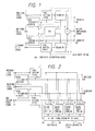
- FIG. 2 is a schematic block diagram for illustrating the configuration of another motion compensation apparatus for describing the basis of the present invention (namely, a second explanatory example.
- the second example has a plurality of micro-shift portions 21 to 24, as well as an optimal signal determination device 25.
- each of the micro-shift portions 21 to 24 is similar to the micro-shift portion 1 consisting of the re-samplers 9 and 10, the coefficient determination device 13 and the adder 14 as indicated by dashed lines in FIG. 1.
- the micro-shift portions 21 to 24 are different in coefficients generated in the coefficient determination device from one another.
- operations of the MV estimating devices 5 and 6 and the pixel shifting devices 7 and 8 are the same as the above described operations of the corresponding devices of the first explanatory example of FIG. 1.
- each of the micro-shift portions 21 to 24 Signals representing a precedent field (or frame) signal, a subsequent field (or frame) signal, a precedent MV and a subsequent MV are input to the micro-shift portions 21 to 24.
- the inside structure or configuration of each of the micro-shift portions 21 to 24 is similar to that of the micro-shift portion 1 as indicated by dashed lines of FIG. 1.
- fundamental operations of each of the micro-shift portions 21 to 24 are similar to those of the portion 1 of FIG. 1 except the coefficients output by the coefficient determination device of each of the micro-shift portions 21 to 24. Practically, such coefficients are obtained by each of the micro-shift portions 21 to 24 by being shifted minutely correspondingly to two motion vectors input thereto.
- the coefficients of groups respectively output by the micro-shift portions 21 to 24 correspond to four kinds of combinations of the values MVA and MVB (for instance, 0 and 0; 0 and 0.25; 0.25 and 0; and 0.25 and 0.25).
- an output signal of each of the micro-shift portions 21 to 24 is input to an optimal signal determination device 25.
- the optimal signal determination device 25 checks how a corresponding motion-compensated signal matches a reference field (or frame) signal. Further, the optimal signal determination device 25 selects the motion-compensated signal which matches the reference field (or frame) signal the best of all of those output from the micro-shift portions 21 to 24 (namely, the optimal signal determination device 25 selects the motion-compensated signal having a smallest error). The selected signal is output through the motion-compensated signal output terminal 15 as an ultimate motion-compensated signal.
- FIG. 3 is a schematic block diagram for illustrating the configuration of a motion compensation apparatus embodying the present invention (namely, an embodiment of the present invention).
- the differences between the second explanatory example (not embodying the present invention) of FIG. 2 and the embodiment of FIG. 3 reside in that micro-shift portions 31 to 34 of the embodiment do not receive vector information and that the number of the micro-shift portions of the embodiment is rather large.
- micro-MV output terminal 27 information on a motion-vector having the magnitude less than one pixel, which indicates the micro-shift portion outputting a selected signal, is output through a micro-MV output terminal 27.
Landscapes
- Engineering & Computer Science (AREA)
- Multimedia (AREA)
- Signal Processing (AREA)
- Television Systems (AREA)
- Image Processing (AREA)
- Color Television Systems (AREA)
- Compression Or Coding Systems Of Tv Signals (AREA)
Claims (4)
- Bewegungskompensationsvorrichtung zum Empfangen einer Information über Bewegungsvektoren und zum Durchführen einer Bewegungskompensation dynamischer Bildsignale mit einer Genauigkeit, die gleich oder feiner als ein Abstand zwischen benachbarten Bildpunkten ist, wobei die Information über Bewegungsvektoren geschätzt wird anhand eines durch ein Bezugsbildsignal oder ein Bezugshalbbildsignal repräsentierten Bezugsbilds oder - halbbilds und eines durch ein vorhergehendes Bildsignal oder ein vorhergehendes Halbbildsignal repräsentierten vorhergehenden Bilds oder Halbbilds, und eines durch ein nachfolgendes Bildsignal oder ein nachfolgendes Halbbildsignal repräsentierten nachfolgenden Bilds oder Halbbilds, wobei die Bewegungskompensationsvorrichtung umfasst:eine Bildpunkteverschiebungseinrichtung (7, 8) zum Verschieben des vorhergehenden bzw. nachfolgenden Bild- oder Halbbildsignals mit einer einem Bildpunkt entsprechenden Genauigkeit entsprechend einem vorhergehenden bzw. einem nachfolgenden Bewegungsvektor, die aus dem vorhergehenden Bild- oder Halbbildsignal und dem Bezugsbild- oder -halbbildsignal bzw. aus dem nachfolgenden Bild- oder Halbbildsignal und dem Bezugsbild- oder -halbbildsignal erhalten werden;eine Vielzahl von Mikro-Verschiebungseinrichtungen (31 bis 34) jeweils zum Wiederabtasten entsprechend fester Koeffizienten der von der Bildpunkteverschiebungseinrichtung ausgegebenen Signale und zum Addieren der sich ergebenden Signale undeine Optimalsignalauswahleinrichtung (25) zum Auswählen eines optimalen Signals, das gegenüber allen der Vielzahl von durch die Vielzahl von Mikro-Verschiebungseinrichtungen (31 bis 34) erzeugten, bewegungskompensierten Bildsignalen am besten mit dem Bezugsbild- oder -halbbildsignal übereinstimmt.
- Bewegungskompensationsvorrichtung nach Anspruch 1, wobeider vorhergehende Bewegungsvektor durch eine Bewegungsvektorschätzeinrichtung (19) unter Verwendung eines Bezugsbild- oder -halbbildsignals und eines vorhergehenden Bild- oder Halbbildsignals erzeugt wird undder nachfolgende Bewegungsvektor durch eine Bewegungsvektorschätzeinrichtung (20) unter Verwendung eines Bezugsbild- oder -halbbildsignals und eines nachfolgenden Bild- oder Halbbildsignals erzeugt wird.
- Bewegungskompensationsvorrichtung nach einem der vorhergehenden Ansprüche, wobeidie Optimalsignalauswahleinrichtung (25) einen Absolutwert eines Fehlers als Übereinstimmungskriterium verwendet.
- Bewegungskompensationsvorrichtung nach einem der Ansprüche 1 und 2, wobeidie Optimalsignalauswahleinrichtung (25) einen mittleren quadratischen Fehler als Übereinstimmungskriterium verwendet.
Applications Claiming Priority (4)
| Application Number | Priority Date | Filing Date | Title |
|---|---|---|---|
| JP31360791 | 1991-10-31 | ||
| JP31360791A JP2611591B2 (ja) | 1991-10-31 | 1991-10-31 | 動き補償装置 |
| JP313607/91 | 1991-10-31 | ||
| EP19920118692 EP0544122B1 (de) | 1991-10-31 | 1992-10-30 | Vorrichtung zur Kompensation von Bewegungen in Bildern |
Related Parent Applications (2)
| Application Number | Title | Priority Date | Filing Date |
|---|---|---|---|
| EP92118692.0 Division | 1992-10-30 | ||
| EP19920118692 Division EP0544122B1 (de) | 1991-10-31 | 1992-10-30 | Vorrichtung zur Kompensation von Bewegungen in Bildern |
Publications (3)
| Publication Number | Publication Date |
|---|---|
| EP0808059A2 EP0808059A2 (de) | 1997-11-19 |
| EP0808059A3 EP0808059A3 (de) | 1998-04-29 |
| EP0808059B1 true EP0808059B1 (de) | 2002-01-09 |
Family
ID=18043359
Family Applications (2)
| Application Number | Title | Priority Date | Filing Date |
|---|---|---|---|
| EP97112635A Expired - Lifetime EP0808059B1 (de) | 1991-10-31 | 1992-10-30 | Bewegungskompensationsvorrichtung |
| EP19920118692 Expired - Lifetime EP0544122B1 (de) | 1991-10-31 | 1992-10-30 | Vorrichtung zur Kompensation von Bewegungen in Bildern |
Family Applications After (1)
| Application Number | Title | Priority Date | Filing Date |
|---|---|---|---|
| EP19920118692 Expired - Lifetime EP0544122B1 (de) | 1991-10-31 | 1992-10-30 | Vorrichtung zur Kompensation von Bewegungen in Bildern |
Country Status (4)
| Country | Link |
|---|---|
| US (1) | US5355168A (de) |
| EP (2) | EP0808059B1 (de) |
| JP (1) | JP2611591B2 (de) |
| DE (2) | DE69232341T2 (de) |
Cited By (1)
| Publication number | Priority date | Publication date | Assignee | Title |
|---|---|---|---|---|
| DE102008050741A1 (de) | 2008-10-08 | 2010-04-15 | Blumenfeld, Nikolai | Mehrschichtiges Bausystem |
Families Citing this family (27)
| Publication number | Priority date | Publication date | Assignee | Title |
|---|---|---|---|---|
| JP2611591B2 (ja) * | 1991-10-31 | 1997-05-21 | 日本ビクター株式会社 | 動き補償装置 |
| US5461423A (en) * | 1992-05-29 | 1995-10-24 | Sony Corporation | Apparatus for generating a motion vector with half-pixel precision for use in compressing a digital motion picture signal |
| JPH05336514A (ja) * | 1992-05-29 | 1993-12-17 | Sony Corp | 画像符号化装置 |
| JPH06113287A (ja) * | 1992-09-30 | 1994-04-22 | Matsushita Electric Ind Co Ltd | 画像符号化装置と画像復号化装置 |
| KR0166724B1 (ko) * | 1993-05-08 | 1999-03-20 | 김광호 | 반화소정확도를 갖는 동벡터추정방법 및 그 장치 |
| CN1085466C (zh) * | 1993-09-14 | 2002-05-22 | 株式会社金星社 | 图象解码器中包括半象素单元运动补偿装置的b帧处理装置 |
| KR970003102B1 (ko) * | 1993-09-17 | 1997-03-14 | 대우전자 주식회사 | 영상 복호기에서의 하프 픽셀 움직임 보상 회로 |
| JP2590705B2 (ja) * | 1993-09-28 | 1997-03-12 | 日本電気株式会社 | 動き補償予測装置 |
| EP0652676A1 (de) * | 1993-11-08 | 1995-05-10 | Sony Corporation | Verfahren und Vorrichtung zur Komprimierung eines digitalen Bewegtbildsignals |
| JP3319133B2 (ja) * | 1994-03-29 | 2002-08-26 | ソニー株式会社 | 画像プリンタ装置 |
| DE69535952D1 (de) * | 1994-03-30 | 2009-06-25 | Nxp Bv | Verfahren und Schaltung zur Bewegungsschätzung zwischen Bildern mit zwei Zeilensprunghalbbildern, und Vorrichtung zur digitalen Signalkodierung mit einer solchen Schaltung |
| US5682438A (en) * | 1994-06-21 | 1997-10-28 | Nippon Steel Corporation | Method and apparatus for determining a motion vector |
| US5684538A (en) | 1994-08-18 | 1997-11-04 | Hitachi, Ltd. | System and method for performing video coding/decoding using motion compensation |
| KR0151210B1 (ko) * | 1994-09-23 | 1998-10-15 | 구자홍 | 엠펙2를 수용하는 반화소 움직임 보상조절장치 |
| US5617149A (en) * | 1994-11-22 | 1997-04-01 | Electronics And Telecommunications Research Institute | Apparatus and method for detecting scene changes using the difference of mad between image frames |
| US5706059A (en) * | 1994-11-30 | 1998-01-06 | National Semiconductor Corp. | Motion estimation using a hierarchical search |
| US5694179A (en) * | 1994-12-23 | 1997-12-02 | Electronics And Telecommunications Research Institute | Apparatus for estimating a half-pel motion in a video compression method |
| US5623313A (en) * | 1995-09-22 | 1997-04-22 | Tektronix, Inc. | Fractional pixel motion estimation of video signals |
| KR0185940B1 (ko) * | 1996-01-11 | 1999-04-15 | 김광호 | 미세한 움직임 추정 방법 및 그 장치 |
| KR100226684B1 (ko) * | 1996-03-22 | 1999-10-15 | 전주범 | 반화소 움직임 추정장치 |
| US6122017A (en) * | 1998-01-22 | 2000-09-19 | Hewlett-Packard Company | Method for providing motion-compensated multi-field enhancement of still images from video |
| ES2207938T3 (es) | 1999-03-02 | 2004-06-01 | Zf Lemforder Metallwaren Ag | Suspension de eje de ejes rigidos. |
| JP4102973B2 (ja) * | 2002-04-24 | 2008-06-18 | 日本電気株式会社 | 動画像の符号化方法および復号化方法、これを用いた装置とプログラム |
| US7408988B2 (en) * | 2002-12-20 | 2008-08-05 | Lsi Corporation | Motion estimation engine with parallel interpolation and search hardware |
| AU2007202789B9 (en) * | 2007-06-15 | 2011-08-18 | Canon Kabushiki Kaisha | High-fidelity motion summarisation method |
| JP2009103889A (ja) * | 2007-10-23 | 2009-05-14 | Hitachi Ltd | 画像表示装置および画像表示方法 |
| CN112908252B (zh) * | 2021-01-26 | 2022-08-23 | 合肥维信诺科技有限公司 | 显示装置及显示面板的补偿方法 |
Citations (1)
| Publication number | Priority date | Publication date | Assignee | Title |
|---|---|---|---|---|
| EP0544122B1 (de) * | 1991-10-31 | 1999-04-28 | Victor Company Of Japan, Limited | Vorrichtung zur Kompensation von Bewegungen in Bildern |
Family Cites Families (12)
| Publication number | Priority date | Publication date | Assignee | Title |
|---|---|---|---|---|
| GB2202706B (en) * | 1987-03-27 | 1991-01-09 | British Broadcasting Corp | Video signal processing |
| US4838685A (en) * | 1987-04-03 | 1989-06-13 | Massachusetts Institute Of Technology | Methods and apparatus for motion estimation in motion picture processing |
| EP0294962B1 (de) * | 1987-06-09 | 1995-07-19 | Sony Corporation | Bewertung von Bewegungsvektoren in Fernsehbildern |
| JPH07112283B2 (ja) * | 1989-02-14 | 1995-11-29 | 日本ビクター株式会社 | 動きベクトル検出装置及び検出方法 |
| GB2236449B (en) * | 1989-09-20 | 1994-05-11 | British Broadcasting Corp | Motion estimation |
| JPH0832048B2 (ja) * | 1990-01-23 | 1996-03-27 | 日本ビクター株式会社 | 動きベクトル検出装置 |
| JP2519113B2 (ja) * | 1990-01-23 | 1996-07-31 | 日本ビクター株式会社 | 動きベクトル情報の伝送方法及びその送信機並びに受信機 |
| JPH03252287A (ja) * | 1990-02-28 | 1991-11-11 | Victor Co Of Japan Ltd | 動画像圧縮装置 |
| DE69029999T2 (de) * | 1990-07-20 | 1997-08-14 | Philips Electronics Nv | Vorrichtung zur Verarbeitung von Bewegungsvektoren |
| EP0474276B1 (de) * | 1990-09-03 | 1997-07-23 | Koninklijke Philips Electronics N.V. | Video-Bewegungsvektorabschätzung mit asymmetrischem Aktualisierungsgebiet |
| JPH04139986A (ja) * | 1990-09-29 | 1992-05-13 | Victor Co Of Japan Ltd | 画像信号の動き補償予測符号化/復号化装置 |
| JPH04189093A (ja) * | 1990-11-22 | 1992-07-07 | Victor Co Of Japan Ltd | 動き補償装置 |
-
1991
- 1991-10-31 JP JP31360791A patent/JP2611591B2/ja not_active Expired - Lifetime
-
1992
- 1992-10-29 US US07/968,124 patent/US5355168A/en not_active Expired - Lifetime
- 1992-10-30 EP EP97112635A patent/EP0808059B1/de not_active Expired - Lifetime
- 1992-10-30 EP EP19920118692 patent/EP0544122B1/de not_active Expired - Lifetime
- 1992-10-30 DE DE69232341T patent/DE69232341T2/de not_active Expired - Fee Related
- 1992-10-30 DE DE69229035T patent/DE69229035D1/de not_active Expired - Lifetime
Patent Citations (1)
| Publication number | Priority date | Publication date | Assignee | Title |
|---|---|---|---|---|
| EP0544122B1 (de) * | 1991-10-31 | 1999-04-28 | Victor Company Of Japan, Limited | Vorrichtung zur Kompensation von Bewegungen in Bildern |
Cited By (1)
| Publication number | Priority date | Publication date | Assignee | Title |
|---|---|---|---|---|
| DE102008050741A1 (de) | 2008-10-08 | 2010-04-15 | Blumenfeld, Nikolai | Mehrschichtiges Bausystem |
Also Published As
| Publication number | Publication date |
|---|---|
| DE69232341D1 (de) | 2002-02-14 |
| EP0544122B1 (de) | 1999-04-28 |
| HK1000864A1 (en) | 2000-04-28 |
| JPH05130581A (ja) | 1993-05-25 |
| EP0544122A1 (de) | 1993-06-02 |
| US5355168A (en) | 1994-10-11 |
| DE69229035D1 (de) | 1999-06-02 |
| EP0808059A2 (de) | 1997-11-19 |
| JP2611591B2 (ja) | 1997-05-21 |
| DE69232341T2 (de) | 2002-06-27 |
| EP0808059A3 (de) | 1998-04-29 |
Similar Documents
| Publication | Publication Date | Title |
|---|---|---|
| EP0808059B1 (de) | Bewegungskompensationsvorrichtung | |
| EP0392671B1 (de) | Bildbewegungsvektordetektor | |
| EP0549681B1 (de) | Videobildverarbeitung | |
| US4691230A (en) | Motion vector detection system of a moving object on a screen | |
| US6061397A (en) | Motion vector detecting device | |
| US5526053A (en) | Motion compensated video signal processing | |
| US7224733B1 (en) | Interpolation filtering method for accurate sub-pixel motion assessment | |
| WO2003024116A1 (en) | Motion estimation and/or compensation | |
| US20020001347A1 (en) | Apparatus and method for converting to progressive scanning format | |
| JPH11243547A (ja) | 動き補償符号化装置及び動き補償符号化方法 | |
| US6714593B1 (en) | Motion compensating prediction of moving image sequences | |
| US6243140B1 (en) | Methods and apparatus for reducing the amount of buffer memory required for decoding MPEG data and for performing scan conversion | |
| US20090073311A1 (en) | Frame rate conversion device and video display device | |
| JP3181431B2 (ja) | 動きベクトルを用いた適応動き内挿信号生成装置 | |
| HK1000864B (en) | Device for compensating motions in images | |
| JPH06326980A (ja) | 動き補償映像信号処理方式 | |
| US7202909B2 (en) | Video signal processing with two stage motion compensation | |
| GB2276999A (en) | Motion compensated video signal processing; detecting "ridge" motion | |
| JP3334317B2 (ja) | 画像照合方法および装置 | |
| JPS6295084A (ja) | テレビジョン信号の高能率符号化及び復号化方法 | |
| JPS6239988A (ja) | 方式変換装置 | |
| JPS62221284A (ja) | 動きベクトル検出装置 | |
| JPH05260446A (ja) | 走査変換方式 | |
| JPH1155673A (ja) | 動きベクトル符号化装置、復号化装置、符号化方法、及び復号化方法 | |
| JPH1198508A (ja) | 動きベクトル検出方法 |
Legal Events
| Date | Code | Title | Description |
|---|---|---|---|
| PUAI | Public reference made under article 153(3) epc to a published international application that has entered the european phase |
Free format text: ORIGINAL CODE: 0009012 |
|
| AC | Divisional application: reference to earlier application |
Ref document number: 544122 Country of ref document: EP |
|
| AK | Designated contracting states |
Kind code of ref document: A2 Designated state(s): DE FR GB |
|
| PUAL | Search report despatched |
Free format text: ORIGINAL CODE: 0009013 |
|
| AK | Designated contracting states |
Kind code of ref document: A3 Designated state(s): DE FR GB |
|
| 17P | Request for examination filed |
Effective date: 19980701 |
|
| 17Q | First examination report despatched |
Effective date: 19990727 |
|
| GRAG | Despatch of communication of intention to grant |
Free format text: ORIGINAL CODE: EPIDOS AGRA |
|
| GRAG | Despatch of communication of intention to grant |
Free format text: ORIGINAL CODE: EPIDOS AGRA |
|
| GRAH | Despatch of communication of intention to grant a patent |
Free format text: ORIGINAL CODE: EPIDOS IGRA |
|
| RIN1 | Information on inventor provided before grant (corrected) |
Inventor name: SUGIYAMA, KENJI |
|
| GRAH | Despatch of communication of intention to grant a patent |
Free format text: ORIGINAL CODE: EPIDOS IGRA |
|
| GRAA | (expected) grant |
Free format text: ORIGINAL CODE: 0009210 |
|
| REG | Reference to a national code |
Ref country code: GB Ref legal event code: IF02 |
|
| AC | Divisional application: reference to earlier application |
Ref document number: 544122 Country of ref document: EP |
|
| AK | Designated contracting states |
Kind code of ref document: B1 Designated state(s): DE FR GB |
|
| PG25 | Lapsed in a contracting state [announced via postgrant information from national office to epo] |
Ref country code: FR Free format text: LAPSE BECAUSE OF FAILURE TO SUBMIT A TRANSLATION OF THE DESCRIPTION OR TO PAY THE FEE WITHIN THE PRESCRIBED TIME-LIMIT Effective date: 20020109 |
|
| REF | Corresponds to: |
Ref document number: 69232341 Country of ref document: DE Date of ref document: 20020214 |
|
| EN | Fr: translation not filed | ||
| PLBE | No opposition filed within time limit |
Free format text: ORIGINAL CODE: 0009261 |
|
| STAA | Information on the status of an ep patent application or granted ep patent |
Free format text: STATUS: NO OPPOSITION FILED WITHIN TIME LIMIT |
|
| 26N | No opposition filed | ||
| PG25 | Lapsed in a contracting state [announced via postgrant information from national office to epo] |
Ref country code: DE Free format text: LAPSE BECAUSE OF NON-PAYMENT OF DUE FEES Effective date: 20030501 |
|
| PGFP | Annual fee paid to national office [announced via postgrant information from national office to epo] |
Ref country code: GB Payment date: 20101027 Year of fee payment: 19 |
|
| REG | Reference to a national code |
Ref country code: GB Ref legal event code: PE20 Expiry date: 20121029 |
|
| PG25 | Lapsed in a contracting state [announced via postgrant information from national office to epo] |
Ref country code: GB Free format text: LAPSE BECAUSE OF EXPIRATION OF PROTECTION Effective date: 20121029 |