EP0807992B1 - Réseau en forme de spirale logarithmique - Google Patents
Réseau en forme de spirale logarithmique Download PDFInfo
- Publication number
- EP0807992B1 EP0807992B1 EP97201481A EP97201481A EP0807992B1 EP 0807992 B1 EP0807992 B1 EP 0807992B1 EP 97201481 A EP97201481 A EP 97201481A EP 97201481 A EP97201481 A EP 97201481A EP 0807992 B1 EP0807992 B1 EP 0807992B1
- Authority
- EP
- European Patent Office
- Prior art keywords
- array
- transducers
- phased array
- rho
- transducer
- Prior art date
- Legal status (The legal status is an assumption and is not a legal conclusion. Google has not performed a legal analysis and makes no representation as to the accuracy of the status listed.)
- Expired - Lifetime
Links
- 238000003491 array Methods 0.000 description 19
- 238000013461 design Methods 0.000 description 7
- 230000004044 response Effects 0.000 description 5
- 230000003750 conditioning effect Effects 0.000 description 3
- 238000013459 approach Methods 0.000 description 2
- 238000010586 diagram Methods 0.000 description 2
- 230000000694 effects Effects 0.000 description 2
- 238000000034 method Methods 0.000 description 2
- 238000012360 testing method Methods 0.000 description 2
- 238000004458 analytical method Methods 0.000 description 1
- 230000015572 biosynthetic process Effects 0.000 description 1
- 230000008859 change Effects 0.000 description 1
- 230000003247 decreasing effect Effects 0.000 description 1
- 238000002405 diagnostic procedure Methods 0.000 description 1
- 238000003384 imaging method Methods 0.000 description 1
- 230000002452 interceptive effect Effects 0.000 description 1
- 230000000670 limiting effect Effects 0.000 description 1
- 230000008569 process Effects 0.000 description 1
- 238000012545 processing Methods 0.000 description 1
- 230000000135 prohibitive effect Effects 0.000 description 1
- 230000005855 radiation Effects 0.000 description 1
- 230000000717 retained effect Effects 0.000 description 1
- 230000001629 suppression Effects 0.000 description 1
Images


Classifications
-
- H—ELECTRICITY
- H01—ELECTRIC ELEMENTS
- H01Q—ANTENNAS, i.e. RADIO AERIALS
- H01Q3/00—Arrangements for changing or varying the orientation or the shape of the directional pattern of the waves radiated from an antenna or antenna system
- H01Q3/26—Arrangements for changing or varying the orientation or the shape of the directional pattern of the waves radiated from an antenna or antenna system varying the relative phase or relative amplitude of energisation between two or more active radiating elements; varying the distribution of energy across a radiating aperture
-
- H—ELECTRICITY
- H01—ELECTRIC ELEMENTS
- H01Q—ANTENNAS, i.e. RADIO AERIALS
- H01Q21/00—Antenna arrays or systems
- H01Q21/06—Arrays of individually energised antenna units similarly polarised and spaced apart
- H01Q21/061—Two dimensional planar arrays
-
- H—ELECTRICITY
- H01—ELECTRIC ELEMENTS
- H01Q—ANTENNAS, i.e. RADIO AERIALS
- H01Q21/00—Antenna arrays or systems
- H01Q21/06—Arrays of individually energised antenna units similarly polarised and spaced apart
- H01Q21/22—Antenna units of the array energised non-uniformly in amplitude or phase, e.g. tapered array or binomial array
-
- H—ELECTRICITY
- H04—ELECTRIC COMMUNICATION TECHNIQUE
- H04R—LOUDSPEAKERS, MICROPHONES, GRAMOPHONE PICK-UPS OR LIKE ACOUSTIC ELECTROMECHANICAL TRANSDUCERS; DEAF-AID SETS; PUBLIC ADDRESS SYSTEMS
- H04R1/00—Details of transducers, loudspeakers or microphones
- H04R1/20—Arrangements for obtaining desired frequency or directional characteristics
- H04R1/32—Arrangements for obtaining desired frequency or directional characteristics for obtaining desired directional characteristic only
- H04R1/40—Arrangements for obtaining desired frequency or directional characteristics for obtaining desired directional characteristic only by combining a number of identical transducers
- H04R1/403—Arrangements for obtaining desired frequency or directional characteristics for obtaining desired directional characteristic only by combining a number of identical transducers loud-speakers
-
- H—ELECTRICITY
- H04—ELECTRIC COMMUNICATION TECHNIQUE
- H04R—LOUDSPEAKERS, MICROPHONES, GRAMOPHONE PICK-UPS OR LIKE ACOUSTIC ELECTROMECHANICAL TRANSDUCERS; DEAF-AID SETS; PUBLIC ADDRESS SYSTEMS
- H04R2201/00—Details of transducers, loudspeakers or microphones covered by H04R1/00 but not provided for in any of its subgroups
- H04R2201/40—Details of arrangements for obtaining desired directional characteristic by combining a number of identical transducers covered by H04R1/40 but not provided for in any of its subgroups
- H04R2201/401—2D or 3D arrays of transducers
-
- H—ELECTRICITY
- H04—ELECTRIC COMMUNICATION TECHNIQUE
- H04R—LOUDSPEAKERS, MICROPHONES, GRAMOPHONE PICK-UPS OR LIKE ACOUSTIC ELECTROMECHANICAL TRANSDUCERS; DEAF-AID SETS; PUBLIC ADDRESS SYSTEMS
- H04R2201/00—Details of transducers, loudspeakers or microphones covered by H04R1/00 but not provided for in any of its subgroups
- H04R2201/40—Details of arrangements for obtaining desired directional characteristic by combining a number of identical transducers covered by H04R1/40 but not provided for in any of its subgroups
- H04R2201/405—Non-uniform arrays of transducers or a plurality of uniform arrays with different transducer spacing
-
- H—ELECTRICITY
- H04—ELECTRIC COMMUNICATION TECHNIQUE
- H04R—LOUDSPEAKERS, MICROPHONES, GRAMOPHONE PICK-UPS OR LIKE ACOUSTIC ELECTROMECHANICAL TRANSDUCERS; DEAF-AID SETS; PUBLIC ADDRESS SYSTEMS
- H04R2430/00—Signal processing covered by H04R, not provided for in its groups
- H04R2430/20—Processing of the output signals of the acoustic transducers of an array for obtaining a desired directivity characteristic
Definitions
- a phased array is a distribution of transducers (receivers, transmitters, or elements which perform both functions) in a certain spatial pattern. By adjusting the phase of the signal transmitted or received by each transducer, the array is made to function a single aperture with a strong, narrow beam in a desired direction. The direction of the beam can be controlled electronically by varying the transducer phases.
- Phased arrays are employed in radar, sonar, medical ultrasonic imaging, military electromagnetic source location, acoustic source location for diagnostic testing, radio astronomy, and many other fields.
- the nature of the signal transmitted or received and the equipment necessary to manipulate it (including the phase adjustment) varies with the application.
- This invention does not address the design of the signal conditioning equipment or the transducers (antennas, microphones, or speakers) themselves. These issues are well understood by workers skilled in the various fields.
- the invention describes a particular spatial arrangement (actually a class of arrangements) of the transducers.
- phased arrays In many applications of phased arrays it is necessary for the system to function over a wide range of frequencies. This generally requires several distinct arrays because any single array designed according to the prior art is limited in the frequency range that it can cover. The frequency limitation arises from the relationship between the design of the array (meaning the the spatial arrangement of the transducers) and the wavelength of the radiation.
- the lowest frequency at which a given array is effective is determined by the overall size of the array in wavelengths.
- the Rayleigh limit of resolution holds that the width of the beam (in radians) is given by the wavelength divided by the aperture size.
- the beam becomes narrower since the ratio of the diameter to wavelength increases.
- a narrower beam is advantageous for most applications, so the array performance in this respect improves as the frequency increases.
- the main beam is joined by additional, undesired, beams at angles different from the intended steering direction.
- These extra beams are known as sidelobes when they are weaker than the main beam, and aliases when they are at the same level as the main beam.
- sidelobes are acceptable provided they are substantially lower than the main beam.
- the required degree of sidelobe suppression depends on the strength of interfering sources relative to the source of interest. To again provided a definite example, it is reasonable to suppose that the sidelobes must be 7 dB below the main lobe.
- the operating frequency range of a square array is 5.72 c / D to 0.707 ( m - 1) c/D.
- the ratio of the upper frequency limit to the lower frequency limit is 6.3:5.72, which makes it essentially a single frequency design.
- phased array operation consists of multiplying the signal from each transducer by a complex phasor and coherently summing the results.
- the phasors are determined so that the resulting sum is a maximum if the transducer signals correspond to a plane wave incident from the steering direction.
- the phasors are all unity. Since the actual signal is normally incident, the beamformer output in the when steering to the correct direction will be n times the response of each individual transducer.
- the array gain is 20 log( n ). If the beam is steered to a direction other than the true incidence direction of the wave, it is hoped that the beamforming sum will be a random phase sum, which will give an average amplitude result equal to the square root of n . In decibels, this result is 10 log( n ).
- the steering phasors will again be unity, and the array will give a spurious maximum response in this direction.
- the problem is that the repeated interelement spacings of the array give rise to repeated phasor values for the steering coefficients for certain directions other than normal incidence. These repeated values, when summed in the beamforming, give a result larger than random phase sum expected for a direction that does not correspond to the true direction of incidence (normal in this case). It should be noted that the problem exists for all true directions for incidence; the normal direction was chosen for illustration because of its analytical simplicity.
- Some of the proposals in the prior art also cluster too many elements in a small region near the center of the array in an effort to have at least some spacings that will always be smaller than a half wavelength.
- This approach fails at both ends of the frequency range.
- the clustered elements are much closer together than a wavelength, so they make a large contribution to the beamforming sum that does not change with the steering direction. The effect is to broaden the central lobe and degrade the low frequency resolution relative to the Rayleigh limit.
- the clustered elements can only partially reduce the sidelobes, because the outer elements arc still spaced on a regular grid which is subject to sidelobe formation. The outer elements can be excluded from the sum at high frequency, but this reduces the array gain.
- the logarithmic spiral is a natural shape which contains no fixed or repeated spacings.
- the lack of fixed distances in the definition of the spiral shape results is a distribution of transducers which systematically avoids repeated spacings, and is consequently free from large sidelobes over a wide range of frequency.
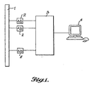
- the array is the key component of a phased array system.
- Other elements include power supplies, signal conditioning equipment, cables, a computer for performing the beamforming processing, and a display device.
- a very simple system is illustrated bellow:
- Fig. 1 is a block diagram of a phased array system.
- the array 1 is a rigid structure in which the transmitting and/or sensing elements are mounted and retained in the predefined spatial relationship.
- the planar array is viewed edge-on in Fig. 1, so the elements cannot be seen.
- the transducers are connected by cables (and possibly other signal conditioning equipment) to a bank of A/D converters 2 . (For transmitting, these would be D/A converters.)
- the signals from the A/D converters are carried to a computer 3 , which performs the mathematical operations associated with beamforming.
- the results (source location and possibly other information) are displayed on the viewing device, 4 .
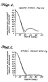
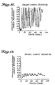
- FIG. 4 through Fig. 17 represent the performance of the two arrays at several frequencies.
- each plot gives two curves: plotted versus the angle off of boresight, theta, are the maximum and minimum beamforming amplitudes over the 360 degree range of the azimuthal angle, phi.
- the maximum and minimum curves match each other. This situation would indicate a circular peak corresponding to the plane wave direction. Differences between the minimum and maximum curves within the central peak indicate that the array output is not uniform with azimuth angle. Peaks that should be circular will appear elliptical. This is not a serious problem for either of the arrays illustrated.
- the array's resolution is defined as the full width of the central peak at the as the 3 dB-down (half-power) point.
- Fig. 4 and Fig. 5 summarize the performance of the square and spiral arrays at 500 Hz. Both arrays have about 34 degrees of resolution and acceptable sidelobes at this frequency.
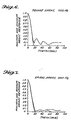
- Fig. 6 and Fig. 7 give array performance at 1000 Hz. Both arrays have 20 Deg. resolution and acceptable sidelobes.
- Fig. 8 and Fig. 9 give the performance of the two arrays at 5000 Hz. It is seen that the resolution of both arrays is about 5 degrees. The square array has aliases at this frequency, as expected. The spiral array has acceptable sidelobes levels.
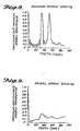
- Fig. 10 and Fig. 11 represent the arrays at 10,000 Hz.
- the central lobes are very tight.
- the square array has so many aliases that it would probably be useless for almost any application.
- the spiral array has acceptable sidelobes.
- Fig. 12 and Fig. 13 give the patterns at 20,000 Hz.
- the square array has even more sidelobes.
- the spiral array has acceptable sidelobes.
- the central peaks have become almost invisible. Some measure to artificially broaden the peaks may be necessary in practice.
- Fig. 14 and Fig. 15 show that the aliases of the square array seem to be filling the hemisphere at 40,000 Hz. The sidelobes of the spiral array are acceptable.
- Fig. 16 and 17 give the array patterns at 80,000 Hz.
- the pattern for the square array seem qualitatively similar to the pattern st 40,000 Hz.
- the spiral array still has acceptable sidelobes.
Landscapes
- Health & Medical Sciences (AREA)
- Otolaryngology (AREA)
- Physics & Mathematics (AREA)
- Engineering & Computer Science (AREA)
- Acoustics & Sound (AREA)
- Signal Processing (AREA)
- Variable-Direction Aerials And Aerial Arrays (AREA)
- Measurement Of Velocity Or Position Using Acoustic Or Ultrasonic Waves (AREA)
- Radar Systems Or Details Thereof (AREA)
- Investigating Or Analyzing Materials By The Use Of Ultrasonic Waves (AREA)
- Ultra Sonic Daignosis Equipment (AREA)
Claims (6)
- Réseau phasé (1) qui comprend une pluralité de transducteurs pour envoyer et/ou recevoir de l'énergie, dans lequel chaque transducteur est couplé par l'intermédiaire d'un convertisseur correspondant (2) à un ordinateur (3), l'ordinateur faisant varier la phase du signal qui est émis sur chaque transducteur et/ou qui est reçu depuis chaque transducteur de manière à diriger l'énergie qui est émise par la pluralité de transducteurs selon une direction souhaitée, de façon respective, afin de reconstruire l'énergie qui est reçue par la pluralité de transducteurs depuis une direction souhaitée, dans lequel les transducteurs sont agencés selon une courbe en spirale logarithmique.
- Réseau phasé selon la revendication 1, dans lequel les transducteurs sont des émetteurs et les convertisseurs sont des convertisseurs numérique-analogique ou N/A.
- Réseau phasé selon la revendication 1, dans lequel les transducteurs sont des récepteurs et les convertisseurs sont des convertisseurs analogique-numérique ou A/N.
- Réseau phasé selon la revendication 3, dans lequel l'ordinateur (3) réalise des opérations mathématiques qui sont associées à une formation de faisceau comprenant la multiplication du signal en provenance de chaque transducteur par un phaseur complexe et la sommation de façon cohérente des résultats.
- Réseau phasé selon l'une quelconque des revendications 1 à 4, dans lequel la spirale logarithmique est définie par rho = rho0 exp (phi/tan(gamma)) où rho et phi sont le rayon et l'angle polaire de n'importe quel point sur la courbe, gamma est l'angle de spirale et rho0 est le rayon initial correspondant à phi = 0.
- Réseau phasé selon l'une quelconque des revendications précédentes, dans lequel l'ordinateur (3) est connecté à un dispositif de visualisation (4) pour afficher les résultats desdites opérations.
Applications Claiming Priority (2)
| Application Number | Priority Date | Filing Date | Title |
|---|---|---|---|
| US64939896A | 1996-05-17 | 1996-05-17 | |
| US649398 | 1996-05-17 |
Publications (2)
| Publication Number | Publication Date |
|---|---|
| EP0807992A1 EP0807992A1 (fr) | 1997-11-19 |
| EP0807992B1 true EP0807992B1 (fr) | 2002-09-11 |
Family
ID=24604609
Family Applications (1)
| Application Number | Title | Priority Date | Filing Date |
|---|---|---|---|
| EP97201481A Expired - Lifetime EP0807992B1 (fr) | 1996-05-17 | 1997-05-16 | Réseau en forme de spirale logarithmique |
Country Status (7)
| Country | Link |
|---|---|
| US (1) | US5838284A (fr) |
| EP (1) | EP0807992B1 (fr) |
| JP (1) | JP3866829B2 (fr) |
| KR (1) | KR100674541B1 (fr) |
| CN (1) | CN1170972A (fr) |
| CA (1) | CA2204444C (fr) |
| DE (1) | DE69715297T2 (fr) |
Families Citing this family (26)
| Publication number | Priority date | Publication date | Assignee | Title |
|---|---|---|---|---|
| US6205224B1 (en) * | 1996-05-17 | 2001-03-20 | The Boeing Company | Circularly symmetric, zero redundancy, planar array having broad frequency range applications |
| US6433754B1 (en) * | 2000-06-20 | 2002-08-13 | Northrop Grumman Corporation | Phased array including a logarithmic spiral lattice of uniformly spaced radiating and receiving elements |
| JP3923431B2 (ja) * | 2001-02-27 | 2007-05-30 | 三菱電機株式会社 | アンテナ装置 |
| US6456244B1 (en) * | 2001-07-23 | 2002-09-24 | Harris Corporation | Phased array antenna using aperiodic lattice formed of aperiodic subarray lattices |
| US6897829B2 (en) * | 2001-07-23 | 2005-05-24 | Harris Corporation | Phased array antenna providing gradual changes in beam steering and beam reconfiguration and related methods |
| US6842157B2 (en) * | 2001-07-23 | 2005-01-11 | Harris Corporation | Antenna arrays formed of spiral sub-array lattices |
| US6583768B1 (en) | 2002-01-18 | 2003-06-24 | The Boeing Company | Multi-arm elliptic logarithmic spiral arrays having broadband and off-axis application |
| US6781560B2 (en) | 2002-01-30 | 2004-08-24 | Harris Corporation | Phased array antenna including archimedean spiral element array and related methods |
| DK174558B1 (da) * | 2002-03-15 | 2003-06-02 | Bruel & Kjaer Sound & Vibratio | Stråleformende transducer-antennesystem |
| US7348929B2 (en) * | 2005-09-08 | 2008-03-25 | Harris Corporation | Phased array antenna with subarray lattices forming substantially rectangular aperture |
| GB2438259B (en) * | 2006-05-15 | 2008-04-23 | Roke Manor Research | An audio recording system |
| US8009507B2 (en) * | 2009-01-09 | 2011-08-30 | The Boeing Company | System and method for adaptable aperture planar phased array |
| US20110158048A1 (en) * | 2009-12-28 | 2011-06-30 | Guigne Jacques Y | Spiral sensor configuration for seismic beamforming and focusing |
| CN101860776B (zh) * | 2010-05-07 | 2013-08-21 | 中国科学院声学研究所 | 一种平面螺旋形传声器阵列 |
| KR101213539B1 (ko) * | 2012-09-03 | 2012-12-18 | (주)에스엠인스트루먼트 | 멤스 마이크로폰 어레이를 이용한 음향감지 장치 및 음향카메라 |
| FR3000862B1 (fr) | 2013-01-08 | 2015-01-09 | ACB Engineering | Dispositifs passifs d'acquisition acoustique large bande et systemes passifs d'imagerie acoustique large bande. |
| US10971817B2 (en) * | 2018-02-15 | 2021-04-06 | Space Exploration Technologies Corp. | Antenna-to-beamformer assignment and mapping in phased array antenna systems |
| CN109356576B (zh) * | 2018-10-23 | 2022-05-03 | 中国石油化工股份有限公司 | 测量平面径向流驱替压力梯度的物模实验装置 |
| EP3772190B1 (fr) * | 2019-07-30 | 2023-03-08 | Panasonic Intellectual Property Management Co., Ltd. | Appareil de communication et antenne |
| US11170752B1 (en) | 2020-04-29 | 2021-11-09 | Gulfstream Aerospace Corporation | Phased array speaker and microphone system for cockpit communication |
| WO2022091370A1 (fr) | 2020-10-30 | 2022-05-05 | Jfeアドバンテック株式会社 | Dispositif de localisation de l'azimut d'une source sonore |
| US12276766B2 (en) | 2021-12-13 | 2025-04-15 | Acteq Llc | Continuous seismic data acquisition having variable density source geometry |
| US12529815B2 (en) | 2021-12-13 | 2026-01-20 | Acteq Llc | Continuous seismic data acquisition having variable density source geometry |
| TWI837638B (zh) * | 2022-04-08 | 2024-04-01 | 圓展科技股份有限公司 | 收音裝置及音訊處理方法 |
| KR102692551B1 (ko) * | 2023-03-24 | 2024-08-06 | 서울대학교산학협력단 | 위상 배열 송신 안테나의 최적의 위상 배열을 검출하기 위한 방법 및 이를 이용한 빔포커싱 어레이 시스템 |
| CN117861983A (zh) * | 2023-12-12 | 2024-04-12 | 上海船舶电子设备研究所(中国船舶集团有限公司第七二六研究所) | 声涡旋换能器阵结构及其布阵方法 |
Family Cites Families (17)
| Publication number | Priority date | Publication date | Assignee | Title |
|---|---|---|---|---|
| US5021796A (en) * | 1971-01-15 | 1991-06-04 | The United States Of America As Represented By The Secretary Of The Navy | Broad band, polarization diversity monopulse antenna |
| US4324140A (en) * | 1980-07-31 | 1982-04-13 | The United States Of America As Represented By The Secretary Of The Navy | Electronically simulated rotating prism for ultrasonic beam scanning |
| US4490721A (en) * | 1980-11-17 | 1984-12-25 | Ball Corporation | Monolithic microwave integrated circuit with integral array antenna |
| JPS5787603A (en) * | 1980-11-21 | 1982-06-01 | Naohisa Goto | Circular polarized wave plane array antenna |
| FR2613558B1 (fr) * | 1987-04-03 | 1994-04-15 | Thomson Csf | Dispositif comportant un combineur radial pour ondes electromagnetiques et procede mettant en oeuvre un combineur radial |
| JP3137260B2 (ja) * | 1989-06-12 | 2001-02-19 | 凸版印刷株式会社 | ラジアルラインスロットアンテナ |
| JP3018353B2 (ja) * | 1989-08-10 | 2000-03-13 | 凸版印刷株式会社 | ラジアルラインスロットアンテナ |
| GB2235590B (en) * | 1989-08-21 | 1994-05-25 | Radial Antenna Lab Ltd | Planar antenna |
| JPH0656928B2 (ja) * | 1989-11-15 | 1994-07-27 | 電気興業株式会社 | 開口面アンテナ |
| KR960009447B1 (en) * | 1991-03-27 | 1996-07-19 | Lg Electronics Inc | A dipole array antenna |
| US5453752A (en) * | 1991-05-03 | 1995-09-26 | Georgia Tech Research Corporation | Compact broadband microstrip antenna |
| JPH082005B2 (ja) * | 1991-06-05 | 1996-01-10 | 八木アンテナ株式会社 | ポリロッドヘリカルアレーアンテナ |
| JP2502417B2 (ja) * | 1991-06-05 | 1996-05-29 | 八木アンテナ株式会社 | 平面アンテナ |
| JPH0575331A (ja) * | 1991-09-17 | 1993-03-26 | Denki Kogyo Co Ltd | 平面アンテナ |
| JPH06268434A (ja) * | 1993-03-12 | 1994-09-22 | Meisei Electric Co Ltd | 等角スパイラルアンテナ |
| FR2712121B1 (fr) * | 1993-11-02 | 1995-12-15 | Thomson Csf | Antenne à réseau d'éléments rayonnants. |
| JP3404568B2 (ja) * | 1999-12-27 | 2003-05-12 | 福井県 | 平面アンテナ |
-
1997
- 1997-03-06 US US08/812,818 patent/US5838284A/en not_active Expired - Lifetime
- 1997-05-05 CA CA002204444A patent/CA2204444C/fr not_active Expired - Lifetime
- 1997-05-15 CN CN97111407A patent/CN1170972A/zh active Pending
- 1997-05-15 JP JP12552997A patent/JP3866829B2/ja not_active Expired - Lifetime
- 1997-05-16 DE DE69715297T patent/DE69715297T2/de not_active Expired - Lifetime
- 1997-05-16 EP EP97201481A patent/EP0807992B1/fr not_active Expired - Lifetime
- 1997-05-17 KR KR1019970019161A patent/KR100674541B1/ko not_active Expired - Lifetime
Also Published As
| Publication number | Publication date |
|---|---|
| KR19980083744A (ko) | 1998-12-05 |
| EP0807992A1 (fr) | 1997-11-19 |
| JPH1070412A (ja) | 1998-03-10 |
| CA2204444A1 (fr) | 1997-11-17 |
| US5838284A (en) | 1998-11-17 |
| DE69715297T2 (de) | 2003-01-02 |
| JP3866829B2 (ja) | 2007-01-10 |
| DE69715297D1 (de) | 2002-10-17 |
| KR100674541B1 (ko) | 2007-06-04 |
| CA2204444C (fr) | 2004-07-13 |
| CN1170972A (zh) | 1998-01-21 |
Similar Documents
| Publication | Publication Date | Title |
|---|---|---|
| EP0807992B1 (fr) | Réseau en forme de spirale logarithmique | |
| CA2204298C (fr) | Reseau planar sans redondance a large gamme de frequences | |
| US5911692A (en) | Sparse two-dimensional wideband ultrasound transducer arrays | |
| JP2005033805A (ja) | 円形スーパーディレクティブ受信アンテナ・アレイ | |
| JPH07273530A (ja) | 放射素子アレイ・アンテナ | |
| US11289807B2 (en) | Three-dimensional phased array antenna | |
| Hald et al. | A class of optimal broadband phased array geometries designed for easy construction | |
| US20060114148A1 (en) | Robust optimal shading scheme for adaptive beamforming with missing sensor elements | |
| US5596550A (en) | Low cost shading for wide sonar beams | |
| Schvartzman et al. | Pattern synthesis and digital beamforming capabilities of the fully digital horus radar | |
| CA3160748A1 (fr) | Antenne multifaisceau | |
| US5767805A (en) | Method for the broadening of a volume antenna beam | |
| Ares et al. | Optimal compromise among sum and difference patterns through sub-arraying | |
| Rahaman et al. | Performane analysis of linearly-arranged concentric circular antenna array using robust ODL technique | |
| Rahaman et al. | Linearly-arranged Concentric Circular Antenna Array Using Robust VDL technique | |
| JPS6376504A (ja) | 空中線装置 | |
| RU2178572C2 (ru) | Приемная антенна гидроакустической станции кругового обзора | |
| JP3239016B2 (ja) | レーダ装置 | |
| CN114361815B (zh) | 一种和差双通道旁瓣抑制相控阵天线系统的使用方法 | |
| JP2007243352A (ja) | アレーアンテナ装置 | |
| Aumann et al. | Synthesis of phased array far-field patterns by focusing in the near-field | |
| Hampson et al. | Initial calibration and beamforming results from the thousand element phased-array | |
| Charpentier et al. | Sectorial direction finding antenna array with a MLP beamformer | |
| US20210173068A1 (en) | Tetrahedral array for constant gain hemispherical coverage | |
| CN118232020A (zh) | 一种相控阵天线及其使用方法 |
Legal Events
| Date | Code | Title | Description |
|---|---|---|---|
| PUAI | Public reference made under article 153(3) epc to a published international application that has entered the european phase |
Free format text: ORIGINAL CODE: 0009012 |
|
| AK | Designated contracting states |
Kind code of ref document: A1 Designated state(s): DE FR GB |
|
| 17P | Request for examination filed |
Effective date: 19980429 |
|
| 17Q | First examination report despatched |
Effective date: 19990407 |
|
| GRAG | Despatch of communication of intention to grant |
Free format text: ORIGINAL CODE: EPIDOS AGRA |
|
| GRAG | Despatch of communication of intention to grant |
Free format text: ORIGINAL CODE: EPIDOS AGRA |
|
| GRAH | Despatch of communication of intention to grant a patent |
Free format text: ORIGINAL CODE: EPIDOS IGRA |
|
| GRAH | Despatch of communication of intention to grant a patent |
Free format text: ORIGINAL CODE: EPIDOS IGRA |
|
| GRAA | (expected) grant |
Free format text: ORIGINAL CODE: 0009210 |
|
| AK | Designated contracting states |
Kind code of ref document: B1 Designated state(s): DE FR GB |
|
| REG | Reference to a national code |
Ref country code: GB Ref legal event code: FG4D |
|
| REF | Corresponds to: |
Ref document number: 69715297 Country of ref document: DE Date of ref document: 20021017 |
|
| ET | Fr: translation filed | ||
| PLBE | No opposition filed within time limit |
Free format text: ORIGINAL CODE: 0009261 |
|
| STAA | Information on the status of an ep patent application or granted ep patent |
Free format text: STATUS: NO OPPOSITION FILED WITHIN TIME LIMIT |
|
| 26N | No opposition filed |
Effective date: 20030612 |
|
| REG | Reference to a national code |
Ref country code: FR Ref legal event code: PLFP Year of fee payment: 20 |
|
| PGFP | Annual fee paid to national office [announced via postgrant information from national office to epo] |
Ref country code: GB Payment date: 20160527 Year of fee payment: 20 Ref country code: DE Payment date: 20160527 Year of fee payment: 20 |
|
| PGFP | Annual fee paid to national office [announced via postgrant information from national office to epo] |
Ref country code: FR Payment date: 20160530 Year of fee payment: 20 |
|
| REG | Reference to a national code |
Ref country code: DE Ref legal event code: R071 Ref document number: 69715297 Country of ref document: DE |
|
| REG | Reference to a national code |
Ref country code: GB Ref legal event code: PE20 Expiry date: 20170515 |
|
| PG25 | Lapsed in a contracting state [announced via postgrant information from national office to epo] |
Ref country code: GB Free format text: LAPSE BECAUSE OF EXPIRATION OF PROTECTION Effective date: 20170515 |