EP0807868A2 - Méthode de détection de l'état du toner à l'aide d'un photodétecteur - Google Patents
Méthode de détection de l'état du toner à l'aide d'un photodétecteur Download PDFInfo
- Publication number
- EP0807868A2 EP0807868A2 EP97303317A EP97303317A EP0807868A2 EP 0807868 A2 EP0807868 A2 EP 0807868A2 EP 97303317 A EP97303317 A EP 97303317A EP 97303317 A EP97303317 A EP 97303317A EP 0807868 A2 EP0807868 A2 EP 0807868A2
- Authority
- EP
- European Patent Office
- Prior art keywords
- toner
- value
- counter
- photosensor
- reference value
- Prior art date
- Legal status (The legal status is an assumption and is not a legal conclusion. Google has not performed a legal analysis and makes no representation as to the accuracy of the status listed.)
- Granted
Links
Images


Classifications
-
- B—PERFORMING OPERATIONS; TRANSPORTING
- B41—PRINTING; LINING MACHINES; TYPEWRITERS; STAMPS
- B41J—TYPEWRITERS; SELECTIVE PRINTING MECHANISMS, i.e. MECHANISMS PRINTING OTHERWISE THAN FROM A FORME; CORRECTION OF TYPOGRAPHICAL ERRORS
- B41J2/00—Typewriters or selective printing mechanisms characterised by the printing or marking process for which they are designed
-
- G—PHYSICS
- G03—PHOTOGRAPHY; CINEMATOGRAPHY; ANALOGOUS TECHNIQUES USING WAVES OTHER THAN OPTICAL WAVES; ELECTROGRAPHY; HOLOGRAPHY
- G03G—ELECTROGRAPHY; ELECTROPHOTOGRAPHY; MAGNETOGRAPHY
- G03G15/00—Apparatus for electrographic processes using a charge pattern
- G03G15/06—Apparatus for electrographic processes using a charge pattern for developing
- G03G15/08—Apparatus for electrographic processes using a charge pattern for developing using a solid developer, e.g. powder developer
- G03G15/0822—Arrangements for preparing, mixing, supplying or dispensing developer
- G03G15/0848—Arrangements for testing or measuring developer properties or quality, e.g. charge, size, flowability
- G03G15/0856—Detection or control means for the developer level
-
- G—PHYSICS
- G03—PHOTOGRAPHY; CINEMATOGRAPHY; ANALOGOUS TECHNIQUES USING WAVES OTHER THAN OPTICAL WAVES; ELECTROGRAPHY; HOLOGRAPHY
- G03G—ELECTROGRAPHY; ELECTROPHOTOGRAPHY; MAGNETOGRAPHY
- G03G15/00—Apparatus for electrographic processes using a charge pattern
- G03G15/06—Apparatus for electrographic processes using a charge pattern for developing
- G03G15/08—Apparatus for electrographic processes using a charge pattern for developing using a solid developer, e.g. powder developer
- G03G15/0822—Arrangements for preparing, mixing, supplying or dispensing developer
- G03G15/0848—Arrangements for testing or measuring developer properties or quality, e.g. charge, size, flowability
- G03G15/0856—Detection or control means for the developer level
- G03G15/0862—Detection or control means for the developer level the level being measured by optical means
Definitions
- the present invention relates generally to a method for detecting the level of toner an image reproduction apparatus, such as a laser printer.
- printers are frequently concerned with detecting the current level of printing material that is left in the printer.
- laser printers are provided with toner sensing apparatus for detecting the status of toner powder in those printers.
- Tachihara et al. US Patent 5,617,121 Ink Jet Recording With Ink Detection, April 1, 1997) discusses a recording head includes discharge ports for discharging ink.
- An ink detection element is provided in the liquid chamber for detecting the presence of ink.
- Murray et al (US Patent 5,610,635, Printer Ink Cartridge With Memory Storage Capacity, March 11, 1997) discusses a printer ink cartridge including a memory storage element. The memory storage element is capable of storing information regarding amount of ink remaining in the cartridge.
- the memory storage element is connected to the control and driver circuit to enable information to be retrieved and stored from the memory storage element.
- the control and driver circuit may also include a counter for counting the number of times the heating elements on the cartridge are energised. The approximate number of times the heating elements have been energised indicates the approximate number of drops of ink that have been applied by the cartridge.
- Stapleton (US Patent 5,596,484 Ink Level Sensing On A Pen Carriage In A Pen Plotter, January 21 1997) discusses an apparatus for sensing whether a liquid with a turbulent surface and contained within a vessel has fallen to a level where the liquid is substantially expended.
- Cowger (US Patent 5,574,484 Level Detection For Ink Cartridges of Ink-Jet Printers, November 12 1996) discusses a sensor that detects the level of ink present in an ink-supply cartridge of an ink-jet type printer. The sensor moves with the reciprocating pen carriage of the printer.
- Ogiri et al. (US Patent 5,508,786, Image Forming Apparatus, April 16, 1996) discusses determining the number of copies which can be outputted corresponding to the defined capacity of the developer.
- Takayanagi et al (US Patent 5,488,395, Liquid Jet Recording Apparatus, January 30, 1996) discusses a liquid jet recording apparatus having a pair of electrodes provided to be immersed in the ink in the container. By applying a voltage between the electrodes, the remainder of the ink is detected by a change in the electric resistance between the electrodes.
- Gu (US Patent 5,485, 191 Image Forming Apparatus Having Tone Correction Function, January 16, 1996) discusses an image forming apparatus including an electrophotographic photosensitive member. For tone controls, a detector detects a state of the tone control image, and the controller controls the electrostatic latent image forming device on the basis of a datum from the detector and predetermined tone correcting information.
- Accatino et al (US Patent 5,414, 452, Recognition Of Ink Expiry In An Ink Jet Printing Head, May 9 1995) discusses ink jet printers in which the print head is connected to an ink reservoir, such as may be used in teleprinter or facsimile apparatuses.
- a logic circuit is used to count the number of drops gradually expelled, and with any necessary correction, compares this number with the maximum number of drops equivalent to a known volume of ink contained on average in the reservoir. Expiry of the ink is indicated as in dependence upon the result of the comparison.
- Gatten (US Patent 5,068, 806, Method of Determining Useful Life of Cartridge For An Ink Jet Printer, November 26, 1991) discusses a computer program in the microcontroller of an ink jet printer-plotter that counts the ink dots fired by the carriage of the printer.
- An object of the present invention is to provide an improved method for detecting the level of toner in a printer.
- the present invention provides a method of detecting toner status in an image reproduction apparatus having a photosensor adapted to detect toner in a toner receptacle comprising:
- a toner status message may be displayed on a display device of the image reproduction apparatus signifying that the toner is empty and a refill is required.
- a toner status message may be displayed on a display device of the image reproduction apparatus signifying that the toner is not empty and a refill is not required.
- the method may further comprise comparing the value of the counter with a second predetermined reference value.
- a toner status message may be displayed on a display device of the image reproduction apparatus signifying that the toner is low and a refill is required.
- a toner status message may be displayed on a display device of the image reproduction apparatus signifying that the toner is not low and a refill is not required.
- the second algorithm is the inverse of the first algorithm.
- the first algorithm may increment the value of the counter and the second algorithm may decrement the value of the counter.
- the present invention also provides an image reproduction apparatus including:
- a contemporary toner sensing apparatus is schematically illustrated, wherein a piezoelectric detector 10 measures the weight of the toner powder in a developing device not shown and outputs the measured value as digital data.
- a data decoder 11 reads the digital data received from the piezoelectric detector 10.
- a CPU or controller 12 determines whether of the status of the toner in the developing device on the basis of the data received from the data decoder 11 and outputs the resultant of determination to a display device not shown.
- Fig. 2A illustrates a circuitry of another toner sensing apparatus employing a photosensor 25.
- An anode of a photodiode is connected to a power source Vcc via a resistance R1 and its cathode is connected to ground.
- Another component of the photosensor may be a phototransistor 21 of which a base receives light from the photodiode 20, a collector termination A is connected to the power source Vcc via a resistance R2 and an emitter is connected to ground.
- the photosensor may also include a transistor 22 of which a base is connected to the collector terminal A of the phototransistor 21 via a resistance R3, a collector terminal B is connected to the power source Vcc via a resistance R4 and an emitter is connected to ground.
- the photosensor 25 is composed of the photodiode 20 for emitting light and the phototransistor 21 for receiving the light from the photodiode 20 as shown in the dotted line in that view.
- Fig. 2B shows how the toner sensing apparatus of Fig. 2A is mounted in the developing device.
- the photodiode 20 and the phototransistor 21 are opposite with each other, having the developer such as toner powder between them, two light transmitting films 22 made of transparent insulating material are provided to make isolation of the photodiode 20 and the phototransistor 21 from the toner having conductivity so as to prevent the two elements from being short-circuited by such toner.
- a toner removing blade 23 is fixed to a rotational shaft 24 and scrapes the toner powder adhered to the surfaces of the light transmitting films 22 as it rotates, so that the light from the photodiode 20 can be transmitted to the phototransistor 21 without interruption.
- the toner powder is provided between the photodiode 20 and the phototransistor 21 by a specified height, both being arranged to face with each other as mentioned before.
- the photodiode 20 can emit light since it is connected to the power source Vcc in forward direction and thus current flows through it all the time.
- At least two situations may arise one is when the toner is properly enough in the developing device and the other is when the toner is short or empty.
- the toner existing in the developing device by a specified height may block the light from the photodiode 20 to be transmitted to the base of the phototransistor 21.
- the phototransistor 21 is turned off and the collector terminal A outputs the signal of high level.
- This signal is then transmitted to the base of the transistor 22 through the resistance R3, so that the transistor 22 is turned on.
- the signal is inverted and amplified at the last output terminal B of the toner sensing apparatus 3, resulting in low level.
- the flowchart of Fig. 3 explains how to detect the status of the toner in the developing device.
- the printer is initialised when a printer engine is on, an upper and lower limit values of a toner empty counter and a reference value are determined. These values give standard points in judging the presence or absence of the toner in the developing device (S1).
- the next step (S2) is followed by judging whether the signal of the last output terminal B of this toner sensing apparatus is low or high. Based on the result of judgment, the next step is performed by counting up the counter values by ones if the output signal is high (S3) and counting down the counting values by ones if low (S4).
- the status of the toner is displayed on any display device as a series of characters "TONER EMPTY” (S6) when the counter value is equal to a larger than the reference value, or as a series of characters “TONER FULL” (S7) when the counter value is smaller than the reference values.
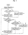
- the flow chart of Fig. 4 explains another method according to this invention, wherein the printer is initialised when a printer engine is on. Then, there exists the steps of determining an upper and lower limit values of a toner empty counter and a first reference value and a second reference value which function as standard points in judging the amount of the remaining toner in the developing device. After the initialisation, the next step is implemented by judging whether the signal of the last output terminal B of this toner sensing apparatus is low or high. Based on the result of judgment, the next step is performed by counting up the counter value by ones if the output signal is high and counting down the counter value by ones if low.
- the flow chart of Fig. 4 explains another method according to this invention, wherein the printer is initialised when a printer engine is on. Then, there exists the steps of determining an upper and lower limit values of a toner empty counter and a first reference value and a second reference value which function as standard points in judging the amount of the remaining toner in the developing device. After the initialisation, the next step is implemented by judging whether the signal of the last output terminal B of this toner sensing apparatus is low or high. Based on the result of judgment, the next step is performed by counting up the counter value by ones if the output signal is high and counting down the counter values by ones if low.
- comparison of the counter value and the first reference value is implemented and the resultant is displayed on any display device as a series of characters "TONER EMPTY" when the counter value is equal to or later than the first reference value.
- an additional comparison is implemented between the counter value and the second reference value and the resultant is displayed on any display device as a series of characters "TONER LOW” when the counter value is equal to or later than the second reference value, or as a series of characters "TONER FULL" when the counter value is smaller than the second reference value.
- the printer is initialised (S1) immediately when a printer engine is on, and at the same time the photodiode 20 emits light since it is connected to the power source Vcc in the forward direction as shown in Figs. 2A and 2B to allow the current to flow through it all the time.
- the toner empty counter is programmed to have the upper limit value and the lower limit value, which is designed to be operated in response to the output from the photosensor, and the reference value which functions as a standard point for judging the presence or absence of the toner in the developing device.
- the light from the photodiode 20 is applied to the base of the phototransistor 21 so that the phototransistor 21 is turned off and the last output terminal B of this toner sensing apparatus outputs the signal of high level as shown in Fig. 2D.
- the toner is properly enough or full, the light transmission from the photodiode 20 to the phototransistor 21 is blocked by the existence of toner, so that the phototransistor 21 is turned on and the last output terminal B of this toner sensing apparatus outputs the signal of low level as shown in Fig. 2C.
- the CPU judges whether the output signal of the terminal B is high or low (S2). Based upon the result of judgment, the next step is selected in either of two ways (low or high signal).
- the high signal signifies what the toner is short or empty, so that the toner empty counter not shown increases the counting value by 1 (S3).
- the low signal signifies what the toner is properly enough or full, so that the counter decrease the counting value by 1 (S4).
- the waveform of Fig. 5A can be obtained by sampling the counter during a specified time T.
- the resultant value is compared with the reference value (S5).
- the counter value is equal to or larger than the reference value
- the high signal is outputted from the terminal B as shown in Fig. 5B and a series of characters "TONER EMPTY" is displayed on the not shown display device to indicate what the toner must be refilled to the user (S6)
- the counter value is smaller than the reference value
- the low signal is outputted from the terminal B as shown in Fig. 5B and a series of characters "TONER FULL” is displayed on the not shown display device to confirm what the toner is properly enough in the developing device to the user (S7).
- the printing system is initialised (S1) immediately when the printer engine is turned on, and at the same time the photodiode 20 emits light since it is connected to the power source Vcc in forward direction as shown in Figs. 2A and 2B to allow the current to flow through it all the time.
- the toner empty counter which is designed to perform the counting operation in accordance to the output signal of the photosensor, is programmed to have the upper limit value and lower limit value, the first reference value and the second reference value which both will be standard points in judging the presence or absence of the toner in the developing device.
- the light from the photodiode 20 is applied to the base of the phototransistor 21 in the absence of the toner, so that the phototransistor 21 is tuned off and the last output terminal B of this toner sensing apparatus outputs the signal of high level as shown in Fig. 2D.
- the toner is properly enough or full, the light transmission from the photodiode 20 to the phototransistor 21 is blocked by the existence of toner, so that the phototransistor 21 is tuned on and the last output terminal B of this toner sensing apparatus outputs the signal of low level as shown in Fig. 2C.
- the CPU judges whether the output signal of the terminal B is high or low (S2). Based upon the result of judgment, the next step is selected in either of two ways. That is, the high signal signifies what the toner is short or empty, so that the toner empty counter not shown increases the counting value by 1 (S3) and the low signal signifies what the toner is properly enough or full, so that the counter decreases the counting value by 1 (S4).
- the waveform of Fig. 6A can be obtained by sampling the counter during a specified time.
- the counter value is compared with the first reference value (S5).
- a first signal of high level is outputted from the terminal B as shown in Fig. 6B and a series of characters "TONER EMPTY" is displayed on the not shown display device to indicate what the toner must be refilled to the user (S6), and however if the counter value is smaller than the first reference value, that value is again compared with the second reference value (S7).
- S7 if the counter value is equal to or larger than the second reference value, a first signal of high level and a second signal of low level are outputted from the terminal B as shown in Figs. 6B and 6C and a series of characters "TONER LOW” is displayed on the not shown display device to indicate what the toner must be refilled before long to the user (S8).
- a first signal and a second signal of low level are outputted from the terminal B as shown in Figs. 6B and a series of characters "TONER FULL" is displayed on the not shown display device to confirm what the toner is properly enough in the developing device (S9).
- this invention detects the status of the toner in the developing device by means of using a photosensor that can be obtained relatively cheaply.
- the noise generated from such a photosensor is sampled in accordance with the integral algorithm and is filtered, bringing an improvement in reliability.
Landscapes
- Physics & Mathematics (AREA)
- General Physics & Mathematics (AREA)
- Dry Development In Electrophotography (AREA)
- Control Or Security For Electrophotography (AREA)
- Accessory Devices And Overall Control Thereof (AREA)
Applications Claiming Priority (2)
| Application Number | Priority Date | Filing Date | Title |
|---|---|---|---|
| KR9616063 | 1996-05-15 | ||
| KR1019960016063A KR100189082B1 (ko) | 1996-05-15 | 1996-05-15 | 포토 센서를 이용한 토너 감지 방법 |
Publications (3)
| Publication Number | Publication Date |
|---|---|
| EP0807868A2 true EP0807868A2 (fr) | 1997-11-19 |
| EP0807868A3 EP0807868A3 (fr) | 1998-02-04 |
| EP0807868B1 EP0807868B1 (fr) | 2003-03-26 |
Family
ID=19458680
Family Applications (1)
| Application Number | Title | Priority Date | Filing Date |
|---|---|---|---|
| EP97303317A Expired - Lifetime EP0807868B1 (fr) | 1996-05-15 | 1997-05-15 | Méthode de détection de l'état du toner à l'aide d'un photodétecteur |
Country Status (6)
| Country | Link |
|---|---|
| US (1) | US6172697B1 (fr) |
| EP (1) | EP0807868B1 (fr) |
| JP (1) | JP3178709B2 (fr) |
| KR (1) | KR100189082B1 (fr) |
| CN (1) | CN1099619C (fr) |
| DE (1) | DE69720098T2 (fr) |
Families Citing this family (5)
| Publication number | Priority date | Publication date | Assignee | Title |
|---|---|---|---|---|
| US7048906B2 (en) | 1995-05-17 | 2006-05-23 | Cedars-Sinai Medical Center | Methods of diagnosing and treating small intestinal bacterial overgrowth (SIBO) and SIBO-related conditions |
| CN100381942C (zh) * | 2003-11-26 | 2008-04-16 | 珠海天威飞马打印耗材有限公司 | 处理盒页产量及页耗粉量检测装置及检测方法 |
| KR101301494B1 (ko) * | 2006-12-05 | 2013-08-29 | 삼성전자주식회사 | 토너 분배시스템 및 그 제어방법 |
| JP5725759B2 (ja) * | 2010-08-18 | 2015-05-27 | キヤノン株式会社 | 画像形成装置 |
| US10057548B2 (en) * | 2015-11-30 | 2018-08-21 | Wipro Limited | Smart closure unit for a writing apparatus |
Citations (5)
| Publication number | Priority date | Publication date | Assignee | Title |
|---|---|---|---|---|
| JPS55163562A (en) * | 1979-06-07 | 1980-12-19 | Canon Inc | Developer replenishing time detector of developing device |
| EP0506423A2 (fr) * | 1991-03-29 | 1992-09-30 | Fujitsu Limited | Système de détection de la quantité de toner pour un appareil d'enregistrement d'images, procédé pour la détection de la quantité de toner et un dispositif de développement pour un appareil d'enregistrement d'images |
| US5317369A (en) * | 1991-09-26 | 1994-05-31 | Murata Kikai Kabushiki Kaisha | Apparatus for detecting toner in image forming apparatus |
| DE19506578A1 (de) * | 1994-02-28 | 1995-08-31 | Samsung Electronics Co Ltd | Vorrichtung zum Ermitteln eines restlichen Tonerpegels |
| US5512980A (en) * | 1993-10-22 | 1996-04-30 | Fujitsu Limited | Method of and apparatus for detecting toner empty |
Family Cites Families (12)
| Publication number | Priority date | Publication date | Assignee | Title |
|---|---|---|---|---|
| US4853718A (en) * | 1988-08-15 | 1989-08-01 | Xerox Corporation | On chip conductive fluid sensing circuit |
| US5068806A (en) * | 1988-12-02 | 1991-11-26 | Spectra-Physics, Inc. | Method of determining useful life of cartridge for an ink jet printer |
| JPH02165963A (ja) * | 1988-12-20 | 1990-06-26 | Canon Inc | 液体墳射記録装置 |
| ATE171897T1 (de) * | 1990-02-26 | 1998-10-15 | Canon Kk | Aufzeichnungsgerät und verfahren zur tintennachweisung |
| US5121343A (en) * | 1990-07-19 | 1992-06-09 | Faris Sadeg M | 3-D stereo computer output printer |
| JP3154261B2 (ja) * | 1991-09-18 | 2001-04-09 | キヤノン株式会社 | 画像形成装置 |
| IT1256844B (it) * | 1992-06-08 | 1995-12-21 | Olivetti & Co Spa | Metodo e dispositivo per il riconoscimento della fine-inchiostro in una testina di stampa a getto d'inchiostro. |
| JP3103470B2 (ja) * | 1993-10-26 | 2000-10-30 | 京セラミタ株式会社 | 画像形成装置 |
| US5596351A (en) * | 1993-12-08 | 1997-01-21 | Calcomp Inc. | Ink level sensing on a pen carriage in a pen plotter |
| US5610635A (en) * | 1994-08-09 | 1997-03-11 | Encad, Inc. | Printer ink cartridge with memory storage capacity |
| JP3315268B2 (ja) * | 1994-09-22 | 2002-08-19 | 株式会社東芝 | 画像形成装置 |
| US5574484A (en) * | 1994-12-20 | 1996-11-12 | Hewlett-Packard Company | Level detection for ink cartridges of ink-jet printers |
-
1996
- 1996-05-15 KR KR1019960016063A patent/KR100189082B1/ko not_active IP Right Cessation
-
1997
- 1997-04-02 JP JP10107697A patent/JP3178709B2/ja not_active Expired - Lifetime
- 1997-05-13 US US08/855,572 patent/US6172697B1/en not_active Expired - Lifetime
- 1997-05-15 EP EP97303317A patent/EP0807868B1/fr not_active Expired - Lifetime
- 1997-05-15 DE DE69720098T patent/DE69720098T2/de not_active Expired - Lifetime
- 1997-05-15 CN CN97113242A patent/CN1099619C/zh not_active Expired - Fee Related
Patent Citations (5)
| Publication number | Priority date | Publication date | Assignee | Title |
|---|---|---|---|---|
| JPS55163562A (en) * | 1979-06-07 | 1980-12-19 | Canon Inc | Developer replenishing time detector of developing device |
| EP0506423A2 (fr) * | 1991-03-29 | 1992-09-30 | Fujitsu Limited | Système de détection de la quantité de toner pour un appareil d'enregistrement d'images, procédé pour la détection de la quantité de toner et un dispositif de développement pour un appareil d'enregistrement d'images |
| US5317369A (en) * | 1991-09-26 | 1994-05-31 | Murata Kikai Kabushiki Kaisha | Apparatus for detecting toner in image forming apparatus |
| US5512980A (en) * | 1993-10-22 | 1996-04-30 | Fujitsu Limited | Method of and apparatus for detecting toner empty |
| DE19506578A1 (de) * | 1994-02-28 | 1995-08-31 | Samsung Electronics Co Ltd | Vorrichtung zum Ermitteln eines restlichen Tonerpegels |
Non-Patent Citations (1)
| Title |
|---|
| PATENT ABSTRACTS OF JAPAN vol. 005, no. 042 (P-053), 20 March 1981 & JP 55 163562 A (CANON INC), 19 December 1980, * |
Also Published As
| Publication number | Publication date |
|---|---|
| DE69720098T2 (de) | 2004-03-04 |
| CN1099619C (zh) | 2003-01-22 |
| JPH1055105A (ja) | 1998-02-24 |
| EP0807868B1 (fr) | 2003-03-26 |
| JP3178709B2 (ja) | 2001-06-25 |
| KR970073975A (ko) | 1997-12-10 |
| CN1196508A (zh) | 1998-10-21 |
| EP0807868A3 (fr) | 1998-02-04 |
| DE69720098D1 (de) | 2003-04-30 |
| KR100189082B1 (ko) | 1999-06-01 |
| US6172697B1 (en) | 2001-01-09 |
Similar Documents
| Publication | Publication Date | Title |
|---|---|---|
| US6456802B1 (en) | Capacity determination for toner or ink cartridge | |
| EP1594702B1 (fr) | Consommables imprimantes comportant une memoire de donnees pour donnees d'etalonnage statique et dynamique | |
| US6431670B1 (en) | Ink level sensing method and apparatus | |
| JP3281116B2 (ja) | インク・ジェット印刷ヘッドにおけるインクの消尽を認識する方法および装置 | |
| US5206668A (en) | Method and apparatus for detecting ink flow | |
| EP1862316A2 (fr) | Appareil de consommation de liquide et procédé de commande de quantité de consommation de liquide | |
| EP0807868B1 (fr) | Méthode de détection de l'état du toner à l'aide d'un photodétecteur | |
| US20050031367A1 (en) | Image forming apparatus | |
| US6505009B2 (en) | Waste toner detection systems and methods for determining the volume of waste toner in a printer cartridge | |
| JP4706238B2 (ja) | 流体量を検出する流体噴射ヘッドを制御可能に再充填するためのシステム及び方法 | |
| JP5058828B2 (ja) | インクジェット記録装置 | |
| KR100341784B1 (ko) | 프린터의 토너잔량 검출방법 | |
| JPH10230624A (ja) | 生成物の量の決定方法、生成物の量の決定装置、電気信号処理装置、タンク、そのタンクを含むカートリッジ、画像形成装置、プリンタ、ファクシミリ装置、及び、マイクロコンピュータ | |
| US6109714A (en) | Ink-jet printing apparatus with a system for detecting remaining amount of ink | |
| KR100366029B1 (ko) | 토너잔량표시방법 | |
| US6188413B1 (en) | Method and device for sensing the quantity of ink remaining in an inkjet printer | |
| WO2004065126A1 (fr) | Procede et systeme d'alimentation en encre et conteneur d'encre | |
| KR0150637B1 (ko) | 레이져 프린터에서의 토너 소모량 감지 장치와 방법 | |
| JP2672813B2 (ja) | インク残量検知方法 | |
| JP4108064B2 (ja) | 印刷システムおよび印刷方法 | |
| JPH09262986A (ja) | 記録装置及び該装置におけるインクの残量判定方法 | |
| JP2009107145A (ja) | 液体消費装置および液体消費量管理方法 | |
| KR19990006013U (ko) | 토너 잔량 감지 장치 |
Legal Events
| Date | Code | Title | Description |
|---|---|---|---|
| PUAI | Public reference made under article 153(3) epc to a published international application that has entered the european phase |
Free format text: ORIGINAL CODE: 0009012 |
|
| AK | Designated contracting states |
Kind code of ref document: A2 Designated state(s): DE FR GB IT |
|
| PUAL | Search report despatched |
Free format text: ORIGINAL CODE: 0009013 |
|
| AK | Designated contracting states |
Kind code of ref document: A3 Designated state(s): DE FR GB IT |
|
| 17P | Request for examination filed |
Effective date: 19971216 |
|
| GRAG | Despatch of communication of intention to grant |
Free format text: ORIGINAL CODE: EPIDOS AGRA |
|
| 17Q | First examination report despatched |
Effective date: 20020417 |
|
| GRAG | Despatch of communication of intention to grant |
Free format text: ORIGINAL CODE: EPIDOS AGRA |
|
| GRAH | Despatch of communication of intention to grant a patent |
Free format text: ORIGINAL CODE: EPIDOS IGRA |
|
| GRAH | Despatch of communication of intention to grant a patent |
Free format text: ORIGINAL CODE: EPIDOS IGRA |
|
| GRAA | (expected) grant |
Free format text: ORIGINAL CODE: 0009210 |
|
| AK | Designated contracting states |
Designated state(s): DE FR GB IT |
|
| REG | Reference to a national code |
Ref country code: GB Ref legal event code: FG4D |
|
| REF | Corresponds to: |
Ref document number: 69720098 Country of ref document: DE Date of ref document: 20030430 Kind code of ref document: P |
|
| ET | Fr: translation filed | ||
| PLBE | No opposition filed within time limit |
Free format text: ORIGINAL CODE: 0009261 |
|
| STAA | Information on the status of an ep patent application or granted ep patent |
Free format text: STATUS: NO OPPOSITION FILED WITHIN TIME LIMIT |
|
| 26N | No opposition filed |
Effective date: 20031230 |
|
| REG | Reference to a national code |
Ref country code: FR Ref legal event code: PLFP Year of fee payment: 19 |
|
| PGFP | Annual fee paid to national office [announced via postgrant information from national office to epo] |
Ref country code: GB Payment date: 20150422 Year of fee payment: 19 Ref country code: DE Payment date: 20150422 Year of fee payment: 19 |
|
| PGFP | Annual fee paid to national office [announced via postgrant information from national office to epo] |
Ref country code: FR Payment date: 20150422 Year of fee payment: 19 Ref country code: IT Payment date: 20150421 Year of fee payment: 19 |
|
| REG | Reference to a national code |
Ref country code: DE Ref legal event code: R119 Ref document number: 69720098 Country of ref document: DE |
|
| GBPC | Gb: european patent ceased through non-payment of renewal fee |
Effective date: 20160515 |
|
| PG25 | Lapsed in a contracting state [announced via postgrant information from national office to epo] |
Ref country code: IT Free format text: LAPSE BECAUSE OF NON-PAYMENT OF DUE FEES Effective date: 20160515 |
|
| REG | Reference to a national code |
Ref country code: FR Ref legal event code: ST Effective date: 20170131 |
|
| PG25 | Lapsed in a contracting state [announced via postgrant information from national office to epo] |
Ref country code: DE Free format text: LAPSE BECAUSE OF NON-PAYMENT OF DUE FEES Effective date: 20161201 Ref country code: FR Free format text: LAPSE BECAUSE OF NON-PAYMENT OF DUE FEES Effective date: 20160531 |
|
| REG | Reference to a national code |
Ref country code: GB Ref legal event code: 732E Free format text: REGISTERED BETWEEN 20170406 AND 20170412 |
|
| PG25 | Lapsed in a contracting state [announced via postgrant information from national office to epo] |
Ref country code: GB Free format text: LAPSE BECAUSE OF NON-PAYMENT OF DUE FEES Effective date: 20160515 |
|
| REG | Reference to a national code |
Ref country code: FR Ref legal event code: TP Owner name: S-PRINTING SOLUTION CO., LTD., KR Effective date: 20170912 |