EP0807788B1 - Grille d'incinération de déchets ménagers - Google Patents
Grille d'incinération de déchets ménagers Download PDFInfo
- Publication number
- EP0807788B1 EP0807788B1 EP97400932A EP97400932A EP0807788B1 EP 0807788 B1 EP0807788 B1 EP 0807788B1 EP 97400932 A EP97400932 A EP 97400932A EP 97400932 A EP97400932 A EP 97400932A EP 0807788 B1 EP0807788 B1 EP 0807788B1
- Authority
- EP
- European Patent Office
- Prior art keywords
- edge
- grid
- incineration
- bars
- fixed
- Prior art date
- Legal status (The legal status is an assumption and is not a legal conclusion. Google has not performed a legal analysis and makes no representation as to the accuracy of the status listed.)
- Expired - Lifetime
Links
- 238000007664 blowing Methods 0.000 claims description 10
- 239000010791 domestic waste Substances 0.000 claims description 6
- 239000002699 waste material Substances 0.000 description 10
- 238000002485 combustion reaction Methods 0.000 description 5
- 238000004056 waste incineration Methods 0.000 description 5
- MWUXSHHQAYIFBG-UHFFFAOYSA-N Nitric oxide Chemical compound O=[N] MWUXSHHQAYIFBG-UHFFFAOYSA-N 0.000 description 3
- 238000001816 cooling Methods 0.000 description 2
- 230000007423 decrease Effects 0.000 description 2
- 238000009434 installation Methods 0.000 description 2
- 239000002245 particle Substances 0.000 description 2
- 239000000779 smoke Substances 0.000 description 2
- 239000010419 fine particle Substances 0.000 description 1
- 238000004519 manufacturing process Methods 0.000 description 1
- 239000002184 metal Substances 0.000 description 1
- 230000035515 penetration Effects 0.000 description 1
- 239000007787 solid Substances 0.000 description 1
Images

Classifications
-
- F—MECHANICAL ENGINEERING; LIGHTING; HEATING; WEAPONS; BLASTING
- F23—COMBUSTION APPARATUS; COMBUSTION PROCESSES
- F23H—GRATES; CLEANING OR RAKING GRATES
- F23H1/00—Grates with solid bars
- F23H1/02—Grates with solid bars having provision for air supply or air preheating, e.g. air-supply or blast fittings which form a part of the grate structure or serve as supports
-
- F—MECHANICAL ENGINEERING; LIGHTING; HEATING; WEAPONS; BLASTING
- F23—COMBUSTION APPARATUS; COMBUSTION PROCESSES
- F23G—CREMATION FURNACES; CONSUMING WASTE PRODUCTS BY COMBUSTION
- F23G5/00—Incineration of waste; Incinerator constructions; Details, accessories or control therefor
-
- F—MECHANICAL ENGINEERING; LIGHTING; HEATING; WEAPONS; BLASTING
- F23—COMBUSTION APPARATUS; COMBUSTION PROCESSES
- F23H—GRATES; CLEANING OR RAKING GRATES
- F23H17/00—Details of grates
-
- F—MECHANICAL ENGINEERING; LIGHTING; HEATING; WEAPONS; BLASTING
- F23—COMBUSTION APPARATUS; COMBUSTION PROCESSES
- F23H—GRATES; CLEANING OR RAKING GRATES
- F23H7/00—Inclined or stepped grates
- F23H7/06—Inclined or stepped grates with movable bars disposed parallel to direction of fuel feeding
- F23H7/08—Inclined or stepped grates with movable bars disposed parallel to direction of fuel feeding reciprocating along their axes
Definitions
- the present invention relates to a grid incineration of household waste.
- this air contributes very little to the combustion of waste and constitutes an air leak not negligible since, in the case of a limited grid laterally by two edge plates, approximately 50% of the air blowing is lost.
- the present invention proposes to solve this problem and it relates to a household waste incineration grid as defined above, characterized in that each edge slap is provided with a series of hollows each receiving a fixed bar.
- This arrangement has three advantages.
- the air flows into a substantially horizontal direction and therefore penetrates the mass of waste, thus effectively participating in their combustion.
- the chicane-shaped game is opposed to the passage to through the grid of fine particles or small metal parts from the mass of waste. At on the contrary, the particles tend to accumulate at the horizontal mouth of the chicane passage and at the plug, further limiting air leakage.
- this arrangement only concerns the bars fixed which, by the classical constitution of such grid, correspond to approximately 85% of the length of the games lateral.
- each hollow has the shape of a rebate vertical plane bottom, extending to the lower edge of the edge plate and whose upper edge has substantially the profile of the corresponding fixed bar.
- the bar is fitted into the rebate with minimum vertical clearance from the bottom of the latter and a minimum horizontal clearance with respect to the edge superior of it.
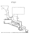
- Figure 1 is a partial view in vertical section a household waste incineration facility.
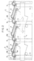
- Figure 2 is a partial sectional view longitudinal of an incineration grid.
- Figure 3 is a front view of an edge plate forming part of such an incineration grid in accordance with the invention.
- Figure 4 is a partial sectional view transverse of a fixed bar of such a grid conforming to the invention.
- Figure 1 is intended to locate a grid incineration, object of the invention, in an installation waste incineration.
- the waste is discharged into a hopper 1 and falls in a well 2 at the bottom of which they are received on a surface horizontal and pushed by a pusher 3 on the grid incineration 4 inclined.
- the bars of the grid 4 are alternately fixed or mobile, as will be seen more precisely below, and gradually move the mass of waste burned towards a evacuation well 6 where the waste falls into a bin cooling 7 and are recovered.
- Figure 2 is shown in more detail the incineration grid 4. It consists of a row of fixed bars 9 and mobile bars 10 translated onto the latter, these fixed and mobile bars being interposed and provided with openings 9A, 10A for blowing air passage.
- the support arrangement 13 of the fixed bars 9 and that of drive in translation 14 of the movable bars 10 are shown schematically in the figure and generally consist of vertical supports fixed for the first and mobile beams for the second.
- the row of bars is laterally limited by a vertical edge plate 11 made up of several panels juxtaposed and united.
- the grid has such an edge plate 11 on each of its edges lateral.
- each hollow 11A has the shape of a rebate of vertical flat bottom, extending to the bottom edge 11B of the plate 11 and whose upper edge 11C has substantially the profile of the corresponding fixed bar 9.
- Each fixed bar 9 is fitted into a rebate 11A as shown in figure 4. Between the edge plate 11 supported by a support structure 12 and the fixed bar 9 is made a minimum clearance taking into account the expansions differentials.
- This game constitutes a flight from chicane to the supply air under the bars 9, 10 in the blowing chamber 5.
- This passage in baffle causes a decrease in the leak rate, a flow substantially horizontal air at the exit of the passage and therefore a air penetration into the waste mass and its contribution to the combustion of it and finally opposes the fall of fine solid particles which tend to contrary to the butcher.
Landscapes
- Engineering & Computer Science (AREA)
- Mechanical Engineering (AREA)
- General Engineering & Computer Science (AREA)
- Chemical & Material Sciences (AREA)
- Combustion & Propulsion (AREA)
- Incineration Of Waste (AREA)
- Disintegrating Or Milling (AREA)
- Processing Of Solid Wastes (AREA)
Description
Claims (2)
- Grille d'incinération de déchets ménagers constituée d'une rangée de barreaux fixes (9) et de barreaux mobiles (10) translatés sur ces derniers, ces barreaux fixes et mobiles étant intercalés et pourvus d'orifices (9A, 10A) de passage d'air de soufflage provenant d'une chambre de soufflage (5) disposée sous la grille, ladite rangée étant limitée latéralement par deux plaques de rive (11), sensiblement verticale,
caractérisée en ce que chaque plaque de rive est pourvue d'une série de creux (11A) recevant chacun un barreau fixe (9). - Grille selon la revendication 1, caractérisée en ce que chaque creux (11A) a la forme d'une feuillure de fond plan vertical, s'étendant jusqu'au bord inférieur (11B) de la plaque et dont le bord supérieur (11C) a sensiblement le profil du barreau fixe (9) correspondant.
Applications Claiming Priority (2)
| Application Number | Priority Date | Filing Date | Title |
|---|---|---|---|
| FR9605911A FR2748552B1 (fr) | 1996-05-13 | 1996-05-13 | Grille d'incineration de dechets menagers |
| FR9605911 | 1996-05-13 |
Publications (2)
| Publication Number | Publication Date |
|---|---|
| EP0807788A1 EP0807788A1 (fr) | 1997-11-19 |
| EP0807788B1 true EP0807788B1 (fr) | 2001-05-30 |
Family
ID=9492066
Family Applications (1)
| Application Number | Title | Priority Date | Filing Date |
|---|---|---|---|
| EP97400932A Expired - Lifetime EP0807788B1 (fr) | 1996-05-13 | 1997-04-24 | Grille d'incinération de déchets ménagers |
Country Status (9)
| Country | Link |
|---|---|
| EP (1) | EP0807788B1 (fr) |
| KR (1) | KR100231495B1 (fr) |
| CN (1) | CN1177082A (fr) |
| AT (1) | ATE201760T1 (fr) |
| DE (1) | DE69704987T2 (fr) |
| DK (1) | DK0807788T3 (fr) |
| ES (1) | ES2157535T3 (fr) |
| FR (1) | FR2748552B1 (fr) |
| TW (1) | TW328985B (fr) |
Families Citing this family (1)
| Publication number | Priority date | Publication date | Assignee | Title |
|---|---|---|---|---|
| DE19851085A1 (de) * | 1998-11-05 | 2000-05-11 | Hdg Bavaria Gmbh Heizkessel & | Schubrostanordnung für einen Festbrennstoff-Kessel o. dgl. |
Family Cites Families (5)
| Publication number | Priority date | Publication date | Assignee | Title |
|---|---|---|---|---|
| DE429514C (de) * | 1924-06-07 | 1926-05-28 | Rudolf Bergmans | Mechanischer Schraegrost fuer Braunkohlen- und Torffeuerungen |
| US2400707A (en) * | 1944-07-24 | 1946-05-21 | Westinghouse Electric Corp | Grate |
| US3358385A (en) * | 1965-04-12 | 1967-12-19 | Fuller Co | Reciprocating grate conveyor with side wall damage preventing means |
| FR2574160A1 (fr) * | 1984-11-30 | 1986-06-06 | Electricite De France | Grille de foyer realisee a partir d'elements permettant un controle ameliore de l'apport en air primaire |
| DE3844493C1 (fr) * | 1988-12-30 | 1990-08-23 | Karl Von Dipl.-Ing. 3057 Neustadt De Wedel |
-
1996
- 1996-05-13 FR FR9605911A patent/FR2748552B1/fr not_active Expired - Lifetime
-
1997
- 1997-04-24 DK DK97400932T patent/DK0807788T3/da active
- 1997-04-24 TW TW086105347A patent/TW328985B/zh active
- 1997-04-24 EP EP97400932A patent/EP0807788B1/fr not_active Expired - Lifetime
- 1997-04-24 DE DE69704987T patent/DE69704987T2/de not_active Expired - Fee Related
- 1997-04-24 ES ES97400932T patent/ES2157535T3/es not_active Expired - Lifetime
- 1997-04-24 AT AT97400932T patent/ATE201760T1/de not_active IP Right Cessation
- 1997-05-07 CN CN97111109A patent/CN1177082A/zh active Pending
- 1997-05-12 KR KR1019970018185A patent/KR100231495B1/ko not_active Expired - Fee Related
Also Published As
| Publication number | Publication date |
|---|---|
| DE69704987D1 (de) | 2001-07-05 |
| FR2748552A1 (fr) | 1997-11-14 |
| ES2157535T3 (es) | 2001-08-16 |
| CN1177082A (zh) | 1998-03-25 |
| EP0807788A1 (fr) | 1997-11-19 |
| ATE201760T1 (de) | 2001-06-15 |
| TW328985B (en) | 1998-04-01 |
| KR100231495B1 (ko) | 1999-11-15 |
| DE69704987T2 (de) | 2002-01-17 |
| DK0807788T3 (da) | 2001-09-17 |
| KR970075655A (ko) | 1997-12-10 |
| FR2748552B1 (fr) | 1998-06-05 |
Similar Documents
| Publication | Publication Date | Title |
|---|---|---|
| CA1264988A (fr) | Grille de foyer realisee a partir d'elements permettant un controle ameliore de l'apport en air primaire | |
| EP0290317B1 (fr) | Foyer de chaudière, notamment pour déchets urbains, à grille composée de barreaux alternativement fixes et mobiles à va-et-vient, à souplesse de réglage accrue | |
| EP0032203B1 (fr) | Capteur de chaleur pouvant être installé notamment dans une cheminée domestique et procédé pour porter à une température plus élevée un fluide tel que de l'eau | |
| EP0807788B1 (fr) | Grille d'incinération de déchets ménagers | |
| KR102728777B1 (ko) | 스토커 소각 및 연소용 공랭 화격자 | |
| CA2114196C (fr) | Four a vapeur a chauffage direct au gaz | |
| EP0091344B1 (fr) | Fours à brûleurs transversaux à récupérateur | |
| BE1009981A3 (fr) | Barreau pour grille d'incineration d'ordures menageres. | |
| US1481366A (en) | Grate bar to burn pulverized coal | |
| EP0277053B1 (fr) | Grille de foyer, avec des barreaux transversaux en éléments solidarisés par leurs faces frontales | |
| JPH09119625A (ja) | ごみ焼却炉用火格子ブロック | |
| FR2553496A1 (fr) | Dispositif de combustion en lit fluidise de combustibles pauvres, notamment de schistes houillers ou bitumineux | |
| JPH0960851A (ja) | 階段摺動式ストーカ | |
| FR2894012A1 (fr) | Barreau pour grille de four d'incineration | |
| FR2536835A1 (fr) | Perfectionnement aux foyers fermes en particulier pour cheminees | |
| FR2758383A1 (fr) | Grille d'incineration de dechets menagers | |
| FR2885404A1 (fr) | Barreau de grille et grille pour foyer a gradins solidaires avec combustion a air dirige | |
| US2372260A (en) | Grate bar | |
| EP0867662B1 (fr) | Cheminée à double foyer avec un dispositif de réglage de la combustion | |
| KR100388042B1 (ko) | 열풍로 버너에서 연소가스의 응축수 분리장치 | |
| KR100784619B1 (ko) | 소각로용 화격자 | |
| US2044348A (en) | Locomotive arch | |
| FR2547393A1 (fr) | Chambre de combustion pour combustibles solides | |
| FR2726073A1 (fr) | Dispositif et procede de distribution d'air de combustion dans des installations de chauffage, notamment a combustibles solides | |
| FR2947037A1 (fr) | Appareil de chauffage avec conduit d'introduction d'air |
Legal Events
| Date | Code | Title | Description |
|---|---|---|---|
| PUAI | Public reference made under article 153(3) epc to a published international application that has entered the european phase |
Free format text: ORIGINAL CODE: 0009012 |
|
| AK | Designated contracting states |
Kind code of ref document: A1 Designated state(s): AT BE CH DE DK ES GB IT LI NL SE |
|
| 17P | Request for examination filed |
Effective date: 19980421 |
|
| RAP1 | Party data changed (applicant data changed or rights of an application transferred) |
Owner name: ALSTOM ENERGY SYSTEMS S.A. |
|
| 17Q | First examination report despatched |
Effective date: 20000301 |
|
| GRAG | Despatch of communication of intention to grant |
Free format text: ORIGINAL CODE: EPIDOS AGRA |
|
| GRAG | Despatch of communication of intention to grant |
Free format text: ORIGINAL CODE: EPIDOS AGRA |
|
| GRAH | Despatch of communication of intention to grant a patent |
Free format text: ORIGINAL CODE: EPIDOS IGRA |
|
| GRAH | Despatch of communication of intention to grant a patent |
Free format text: ORIGINAL CODE: EPIDOS IGRA |
|
| GRAA | (expected) grant |
Free format text: ORIGINAL CODE: 0009210 |
|
| AK | Designated contracting states |
Kind code of ref document: B1 Designated state(s): AT BE CH DE DK ES GB IT LI NL SE |
|
| REF | Corresponds to: |
Ref document number: 201760 Country of ref document: AT Date of ref document: 20010615 Kind code of ref document: T |
|
| REG | Reference to a national code |
Ref country code: CH Ref legal event code: EP |
|
| REG | Reference to a national code |
Ref country code: CH Ref legal event code: NV Representative=s name: CABINET ROLAND NITHARDT CONSEILS EN PROPRIETE INDU |
|
| ITF | It: translation for a ep patent filed | ||
| REF | Corresponds to: |
Ref document number: 69704987 Country of ref document: DE Date of ref document: 20010705 |
|
| REG | Reference to a national code |
Ref country code: ES Ref legal event code: FG2A Ref document number: 2157535 Country of ref document: ES Kind code of ref document: T3 |
|
| GBT | Gb: translation of ep patent filed (gb section 77(6)(a)/1977) |
Effective date: 20010810 |
|
| REG | Reference to a national code |
Ref country code: DK Ref legal event code: T3 |
|
| REG | Reference to a national code |
Ref country code: GB Ref legal event code: IF02 |
|
| PLBE | No opposition filed within time limit |
Free format text: ORIGINAL CODE: 0009261 |
|
| STAA | Information on the status of an ep patent application or granted ep patent |
Free format text: STATUS: NO OPPOSITION FILED WITHIN TIME LIMIT |
|
| 26N | No opposition filed | ||
| REG | Reference to a national code |
Ref country code: CH Ref legal event code: PFA Free format text: ALSTOM ENERGY SYSTEMS S.A. TRANSFER- ABB ALSTOM POWER COMBUSTION * ABB ALSTOM POWER COMBUSTION -DANN IN- ALSTOM POWER BOILERS |
|
| NLT1 | Nl: modifications of names registered in virtue of documents presented to the patent office pursuant to art. 16 a, paragraph 1 |
Owner name: ALSTOM POWER BOILERS;ABB ALSTOM POWER COMBUSTION |
|
| BECN | Be: change of holder's name |
Effective date: 20020612 |
|
| PGFP | Annual fee paid to national office [announced via postgrant information from national office to epo] |
Ref country code: CH Payment date: 20030318 Year of fee payment: 7 |
|
| PGFP | Annual fee paid to national office [announced via postgrant information from national office to epo] |
Ref country code: NL Payment date: 20030325 Year of fee payment: 7 |
|
| PGFP | Annual fee paid to national office [announced via postgrant information from national office to epo] |
Ref country code: GB Payment date: 20030326 Year of fee payment: 7 |
|
| PGFP | Annual fee paid to national office [announced via postgrant information from national office to epo] |
Ref country code: DE Payment date: 20030331 Year of fee payment: 7 |
|
| PGFP | Annual fee paid to national office [announced via postgrant information from national office to epo] |
Ref country code: SE Payment date: 20030402 Year of fee payment: 7 |
|
| PGFP | Annual fee paid to national office [announced via postgrant information from national office to epo] |
Ref country code: AT Payment date: 20030403 Year of fee payment: 7 |
|
| PGFP | Annual fee paid to national office [announced via postgrant information from national office to epo] |
Ref country code: DK Payment date: 20030404 Year of fee payment: 7 |
|
| PGFP | Annual fee paid to national office [announced via postgrant information from national office to epo] |
Ref country code: ES Payment date: 20030422 Year of fee payment: 7 |
|
| PGFP | Annual fee paid to national office [announced via postgrant information from national office to epo] |
Ref country code: BE Payment date: 20030423 Year of fee payment: 7 |
|
| PG25 | Lapsed in a contracting state [announced via postgrant information from national office to epo] |
Ref country code: GB Free format text: LAPSE BECAUSE OF NON-PAYMENT OF DUE FEES Effective date: 20040424 Ref country code: AT Free format text: LAPSE BECAUSE OF NON-PAYMENT OF DUE FEES Effective date: 20040424 |
|
| PG25 | Lapsed in a contracting state [announced via postgrant information from national office to epo] |
Ref country code: SE Free format text: LAPSE BECAUSE OF NON-PAYMENT OF DUE FEES Effective date: 20040425 |
|
| PG25 | Lapsed in a contracting state [announced via postgrant information from national office to epo] |
Ref country code: ES Free format text: LAPSE BECAUSE OF NON-PAYMENT OF DUE FEES Effective date: 20040426 |
|
| PG25 | Lapsed in a contracting state [announced via postgrant information from national office to epo] |
Ref country code: LI Free format text: LAPSE BECAUSE OF NON-PAYMENT OF DUE FEES Effective date: 20040430 Ref country code: DK Free format text: LAPSE BECAUSE OF NON-PAYMENT OF DUE FEES Effective date: 20040430 Ref country code: CH Free format text: LAPSE BECAUSE OF NON-PAYMENT OF DUE FEES Effective date: 20040430 Ref country code: BE Free format text: LAPSE BECAUSE OF NON-PAYMENT OF DUE FEES Effective date: 20040430 |
|
| BERE | Be: lapsed |
Owner name: *ALSTOM POWER BOILER Effective date: 20040430 |
|
| PG25 | Lapsed in a contracting state [announced via postgrant information from national office to epo] |
Ref country code: NL Free format text: LAPSE BECAUSE OF NON-PAYMENT OF DUE FEES Effective date: 20041101 |
|
| PG25 | Lapsed in a contracting state [announced via postgrant information from national office to epo] |
Ref country code: DE Free format text: LAPSE BECAUSE OF NON-PAYMENT OF DUE FEES Effective date: 20041103 |
|
| EUG | Se: european patent has lapsed | ||
| GBPC | Gb: european patent ceased through non-payment of renewal fee |
Effective date: 20040424 |
|
| REG | Reference to a national code |
Ref country code: CH Ref legal event code: PL |
|
| NLV4 | Nl: lapsed or anulled due to non-payment of the annual fee |
Effective date: 20041101 |
|
| PG25 | Lapsed in a contracting state [announced via postgrant information from national office to epo] |
Ref country code: IT Free format text: LAPSE BECAUSE OF NON-PAYMENT OF DUE FEES Effective date: 20050424 |
|
| REG | Reference to a national code |
Ref country code: ES Ref legal event code: FD2A Effective date: 20040426 |