EP0807716A2 - Large-scale cleaning vehicle - Google Patents
Large-scale cleaning vehicle Download PDFInfo
- Publication number
- EP0807716A2 EP0807716A2 EP97107835A EP97107835A EP0807716A2 EP 0807716 A2 EP0807716 A2 EP 0807716A2 EP 97107835 A EP97107835 A EP 97107835A EP 97107835 A EP97107835 A EP 97107835A EP 0807716 A2 EP0807716 A2 EP 0807716A2
- Authority
- EP
- European Patent Office
- Prior art keywords
- cleaning vehicle
- brush
- frame
- rotating brush
- scale
- Prior art date
- Legal status (The legal status is an assumption and is not a legal conclusion. Google has not performed a legal analysis and makes no representation as to the accuracy of the status listed.)
- Granted
Links
- 238000004140 cleaning Methods 0.000 title claims abstract description 154
- XLYOFNOQVPJJNP-UHFFFAOYSA-N water Substances O XLYOFNOQVPJJNP-UHFFFAOYSA-N 0.000 claims abstract description 48
- 239000010813 municipal solid waste Substances 0.000 claims abstract description 45
- 238000010408 sweeping Methods 0.000 claims abstract description 45
- 210000000078 claw Anatomy 0.000 claims description 14
- 238000003780 insertion Methods 0.000 claims description 14
- 230000037431 insertion Effects 0.000 claims description 14
- 235000013358 Solanum torvum Nutrition 0.000 claims 1
- 240000002072 Solanum torvum Species 0.000 claims 1
- 239000000463 material Substances 0.000 claims 1
- 239000004033 plastic Substances 0.000 claims 1
- 238000000034 method Methods 0.000 abstract description 2
- 230000033001 locomotion Effects 0.000 description 3
- 239000012141 concentrate Substances 0.000 description 2
- 238000010586 diagram Methods 0.000 description 2
- 239000000428 dust Substances 0.000 description 2
- 230000003247 decreasing effect Effects 0.000 description 1
- 238000012986 modification Methods 0.000 description 1
- 230000004048 modification Effects 0.000 description 1
- 230000000630 rising effect Effects 0.000 description 1
- 238000005406 washing Methods 0.000 description 1
Images


Classifications
-
- E—FIXED CONSTRUCTIONS
- E01—CONSTRUCTION OF ROADS, RAILWAYS, OR BRIDGES
- E01H—STREET CLEANING; CLEANING OF PERMANENT WAYS; CLEANING BEACHES; DISPERSING OR PREVENTING FOG IN GENERAL CLEANING STREET OR RAILWAY FURNITURE OR TUNNEL WALLS
- E01H1/00—Removing undesirable matter from roads or like surfaces, with or without moistening of the surface
- E01H1/02—Brushing apparatus, e.g. with auxiliary instruments for mechanically loosening dirt
- E01H1/04—Brushing apparatus, e.g. with auxiliary instruments for mechanically loosening dirt taking- up the sweepings, e.g. for collecting, for loading
- E01H1/047—Collecting apparatus characterised by the hopper or by means for unloading the hopper
-
- E—FIXED CONSTRUCTIONS
- E01—CONSTRUCTION OF ROADS, RAILWAYS, OR BRIDGES
- E01H—STREET CLEANING; CLEANING OF PERMANENT WAYS; CLEANING BEACHES; DISPERSING OR PREVENTING FOG IN GENERAL CLEANING STREET OR RAILWAY FURNITURE OR TUNNEL WALLS
- E01H1/00—Removing undesirable matter from roads or like surfaces, with or without moistening of the surface
- E01H1/02—Brushing apparatus, e.g. with auxiliary instruments for mechanically loosening dirt
- E01H1/05—Brushing apparatus, e.g. with auxiliary instruments for mechanically loosening dirt with driven brushes
-
- E—FIXED CONSTRUCTIONS
- E01—CONSTRUCTION OF ROADS, RAILWAYS, OR BRIDGES
- E01H—STREET CLEANING; CLEANING OF PERMANENT WAYS; CLEANING BEACHES; DISPERSING OR PREVENTING FOG IN GENERAL CLEANING STREET OR RAILWAY FURNITURE OR TUNNEL WALLS
- E01H1/00—Removing undesirable matter from roads or like surfaces, with or without moistening of the surface
- E01H1/08—Pneumatically dislodging or taking-up undesirable matter or small objects; Drying by heat only or by streams of gas; Cleaning by projecting abrasive particles
- E01H1/0827—Dislodging by suction; Mechanical dislodging-cleaning apparatus with independent or dependent exhaust, e.g. dislodging-sweeping machines with independent suction nozzles ; Mechanical loosening devices working under vacuum
- E01H1/0836—Apparatus dislodging all of the dirt by suction ; Suction nozzles
- E01H1/0845—Apparatus dislodging all of the dirt by suction ; Suction nozzles with mechanical loosening or feeding instruments for the dirt to be sucked- up, e.g. brushes, scrapers
Definitions
- the present invention relates to large-scale cleaning vehicles. More specifically, the present invention relates to a large-scale cleaning vehicle that is pushed forward using a forklift vehicle. The present invention also relates to structural elements arid accessories for the same.
- a frame 1 serves as a main body of a conventional cleaning vehicle, on which is mounted an engine 2 and a blower 3. On either side of the front section of frame 1 are mounted cone-shaped rotating brushes 4, which are oriented downward and which draw together debris toward the center.
- Engine 2 drives blower 3 and rotating brushes 4.
- a hopper 6 is connected to a duct 5 of blower 3. Hopper 6 is disposed on frame 1 behind blower 3, and a debris evacuation opening 7 is disposed behind and below hopper 6.
- a filter 8 is also disposed in hopper 6.
- a flexible tube 9 is fitted into a side wall of hopper 6. The lower end of flexible tube 9 forms a suction opening 10. Flexible tube 9 is hung down from an appropriate position on frame 1.
- An engagement member 11 for engaging a lift bracket of a forklift vehicle is disposed toward the back of frame 1.
- the rotating brushes are separated from the ground.
- motor 2 drives blower 3 and moves brushes 4
- debris is moved through suction opening 10 and filter 8 disposed at an upper portion within hopper 6 collects the suctioned debris.
- the rotating brushes 4 of the conventional large-scale cleaning vehicle are fixed to a rotating brush support member so that debris can be collected over a wider span than the width of a standard large-scale cleaning vehicle.
- the present invention can also make tight maneuvers.
- the operator of the forklift can evacuate the debris collected in the debris collection box while staying in the driver's seat. Furthermore, when the present invention is used on uneven surfaces, the claw and the bottom surface are kept from being damaged.
- the rotating brush When the rotating brush is not being used, the brush can be pulled up so that the efficiency of the brush is not decreased and the life-span is increased.
- a large-scale trash removal device is attached to the front of the large-scale cleaning vehicle and can be raised when there is no large-scale trash.
- the height of the large-scale trash removal device can be adjusted according to the height of the ground with which it is in contact.
- a large-scale cleaning vehicle for operation with a forklift, includes rotation brushes for sweeping debris toward a center of said cleaning vehicle, a sweeping brush for sweeping the debris into a debris collection box and a fan for pulling said debris into said debris collection box without the need for a motor in the cleaning vehicle.
- Each of the rotation brushes, the sweeping brush, and the fan are rotatably connected to a rear wheel of the cleaning vehicle such that when the cleaning vehicle is moved, the brushes and fan are rotated.
- the cleaning vehicle further includes a vertical adjustment for the rotation brushes to lift them when they are not needed, a lateral adjustment for the rotation brushes to adjust a width of sweeping, an audible warning for pedestrians, a water sprinkler system to aid in the cleaning process, and a large-scale trash removal brush mounted in front of the cleaning vehicle to push large-scale trash.
- a large-scale cleaning vehicle pushed by a forklift vehicle comprising; a frame having roughly a cube shape, rotating brushes are attached downward at ends of a front portion of said frame, a rear wheel and a front wheel supporting said frame, a casing within said frame, said casing being roughly cube shaped and having a top surface and a rear side surface left open, a filter is connected to said top surface of said casing, a debris collection box is movably attached inside said casing, said debris collection box having a top surface and a rear side surface left open, a rotation of said rear wheel is transferred to said pair of rotating brushes disposed on the front of said large-scale cleaning vehicle, said rotation being transferred using a rotational transfer member, debris is swept toward a center and rear portion of a central portion of said large-scale cleaning vehicle, said rotation of said rear wheel is also transferred to a sweeping brush disposed at the rear of said large-scale cleaning vehicle using another rotational transfer member, debris swept by said rotating
- a large-scale cleaning vehicle comprising: a vehicle body flame is supported by a pair of rear wheels and a single front-wheel caster, a fork insertion member is movably attached to said frame, brackets for supporting rotating brush attachment members are attached pointing downward to the bottom of the ends of said frame, said rotating brush attachment member, to which said rotating brush is attached pointing downward, is attached integrally to a connecting rod, an end of said connecting rod is movably mounted to a back of said bracket for supporting said rotating brush attachment member, a plurality of holes is formed on said bracket and said rotating brush attachment member, prescribed holes are made continuous and a fixing pin is inserted through said holes, and on said bracket is disposed a vertical rod for applying tension to a belt disposed across pulleys for rotating said rotating brush.
- a large-scale cleaning vehicle with a water sprinkling device comprising: a vehicle body frame, a fork insertion member movably attached to said vehicle body frame supported by a pair of rear wheels and a single front wheel, a rotating brush support bracket is attached pointing downward on a bottom of said frame, a rotating brush attached to an end of said rotating brush support bracket, a water tank holding a volume of water mounted on said frame, a water sprinkler pipe is disposed across a front of said frame, said water sprinkler pipe having a plurality of nozzles, and said volume of water being connected to said water sprinkler pipe such that said water passes from said water tank through said water sprinkler pipe and out of said plurality of nozzles.
- a cleaning vehicle comprising: a frame having a front end and a rear end, an insertion member pivotally connected at said front end of said frame, said insertion member being shaped to receive a connecting member from a second vehicle which supplies a motive force to said cleaning vehicle; said frame being supported by a rear wheel and a front wheel, a rotating brush assembly connected to said front end of said frame, at least one rotating brush rotatably connected to t least one rotating brush support plate, said at least one rotating brush support plate being pivotally connected to said rotating brush assembly, said at least one rotating brush support plate being pivotable between an outer position and an inner position to adjust a width of sweeping, a sweeping brush positioned toward a rear end of said frame, a debris collection box hingably connected at a bottom of said tray, a fan being operationally connected to said debris collection box such that rotation of said fan pulls debris swept by said sweeping brush into said debris collection box, and each of said at least one rotating brush, said
- the rotating brushes, sweeping brushes, and fans without an engine.
- the rotation of the wheel shafts is used to rotate the rotating brushes, sweeping brushes, and fans.
- the large-scale cleaning vehicle of the present invention is pushed forward by a forklift vehicle.
- the accompanying rotation of the rear wheels of the large-scale cleaning vehicle is transferred to a shaft of a sweeping brush through the meshing of gears, thus rotating the sweeping brush.
- the rotation of the shalt of the sweeping brush is transferred to a shaft disposed on the front of the large-scale cleaning vehicle using a transfer member such as a belt or the like.
- the rotation of this shaft is then transferred to the shaft of a fan or a rotating brush using a transfer member such as a belt, thus rotating the fan or rotating brush.
- the large-scale cleaning vehicle of the present invention is able to perform tight maneuvers. This is accomplished by movably disposing a fork fitting member on the upper surface of the large-scale cleaning vehicle.
- the fork fitting member is formed with a shape that allows the fork of a forklift vehicle to be loosely inserted.
- the fork fitting member is movably attached to the upper surface of the large-scale cleaning vehicle of the present invention.
- the fork of the forklift vehicle is loosely inserted into the fork fitting member, and the large-scale cleaning vehicle is moved forward.
- the swinging of the fork fitting member swings the large-scale cleaning vehicle to the left and right, thus allowing the large-scale cleaning vehicle to make tight maneuvers.
- the large-scale cleaning vehicle of the present invention makes it possible for the forklift operator to eject the debris collected in the debris collection box without getting up from the driver's seat.
- a ratchet that can move up and down is attached to a frame, which forms the vehicle body of the large-scale cleaning vehicle. The bend in the ratchet is suspended at the bottom of the debris collection box, and the other end of the ratchet is connected to a wire. The wire is operated by the forklift operator to eject the debris held in the debris collection box.
- the top side and one of the side walls of the debris collection box in the frame are left open.
- the debris collection box is movably connected to the frame.
- the opened side wall and the bottom surface of the opposite wall are suspended by the hooked portion of the ratchet.
- the ratchet is drawn up.
- the debris collection box, which is suspended from the hooked portion of the ratchet is swung, and the debris held in the debris collection box is ejected outside from the open side.
- the claw disposed on the debris collection box and the bottom surface of the debris collection box are prevented from being damaged.
- a caster disposed on a side surface of the debris collection box comes into contact with the ground before the claw or the bottom surface of the debris collection box does. This protects the claw and the bottom surface of the debris collection box.
- Casters are movably attached on the two side surfaces of the debris collection box and are connected with a coil spring to the side surfaces.
- a stopper is disposed on the side surface of the debris collection box in order to keep the lower edge of the caster slightly closer to the ground than the claw and the bottom surface of the debris collection box. Since the caster is always kept closer to the ground than the claw and the bottom surface of the debris collection box, the large-scale cleaning vehicle of the present invention can be used over uneven surfaces without damaging the claw or the bottom surface of the debris collection box.
- a rotating brush support plate is attached pointing downward to the bottom part of the vehicle body frame.
- On the inner surface of the rotating brush support plate is attached a pair of upper and lower brackets to hold the upper and lower portions of a rotating brush attachment member.
- a connecting rod is formed integrally with the rotating brush attachment member. The end of the connecting rod is movably mounted into the back section of the bracket, and the connecting rod is passed through holes formed on the bracket and the rotating brush attachment member.
- the connecting rod is fixed between the rotating brushes using a fixing pin. This allows the rotating brushes to move to the left and right.
- Hollow caster attachment legs are attached downward to the vehicle body at a central position between the rotating brushes, which are attached downward on the ends of the vehicle body frame at the front of the large-scale cleaning vehicle.
- the rotatable front-wheel caster is mounted downward on a support plate.
- the support plate is fixed to the bottom end of a shaft which is rotatably fitted within the lower portion of the caster attachment leg so that it can slide up and down.
- a bracket is disposed on the support plate, and the bent portion of a foot lever formed in a shape of a bell crank is movably mounted to the bracket.
- a connecting rod connects one end of the foot lever and the caster attachment leg.
- a tension spring elastically supports the connecting point between the connecting rod and the caster attachment leg and the connection point between the foot lever and the bracket. Upward and downward motions of the foot lever allow the rotating brush to move up and down.
- a large-scale trash collection brush or an elastic plate such as a rubber plate is attached to the large-scale cleaning vehicle so that it can be lifted up or down.
- a water tank is mounted on top of the frame of the large-scale cleaning vehicle.
- a nozzle is disposed on the front of the frame, and a water sprinkler pipe is disposed across the frame to serve as a water sprinkler device for the large-scale cleaning vehicle.
- a sensor and a sound generating device is attached and the sound generating device is activated when the fork is attached or removed.
- Fig. 1 is an elevational side-view of a large-scale cleaning vehicle according to the present invention.
- Fig. 2 is a plan drawing of the large-scale cleaning vehicle of Fig. 1.
- Fig. 3a is a side-view of a fork fitting member of the large-scale cleaning vehicle of Fig. 1, viewed from the left side.
- Fig. 3b is a front-view of the fork fitting member of Fig. 3a.
- Fig. 4 is an enlarged, schematic diagram of the area around a debris collection box of the large scale cleaning vehicle of the present invention.
- Fig. 5 is an elevational side-view showing how the large-scale cleaning vehicle of the present invention is used.
- Fig. 6 is an elevational side-view showing an example of conventional large-scale cleaning machine.
- Fig. 7 is a perspective view of an embodiment of the large-scale cleaning vehicle of the present invention.
- Fig. 8 is a schematic plan drawing of one of the rotating brushes of the large-scale cleaning vehicle of Fig. 7.
- Fig. 9 is a schematic diagram viewed from the side of the large-scale cleaning vehicle of Fig. 7.
- Fig. 10 is a partial elevation front-view of the main elements of the large-scale cleaning vehicle of the present invention with a foot lever for lifting up the rotating brush.
- Fig. 11 is an elevational side-view of the main elements of the large-scale cleaning vehicle of the present invention with a foot lever for lifting up the rotating brush of Fig. 10.
- Fig. 12 is a cross-sectional view along the XII-XII line in Fig. 10.
- Fig. 13 is an elevational side-view showing another embodiment of the present invention with a large-scale trash removal device.
- Fig. 14 is a plan drawing showing how the large-scale trash removal device of Fig. 13 is used.
- Fig. 15 is an elevational front-view, showing how the large-scale trash removal device of Fig. 13 is used.
- Fig. 16 is an elevational side-view showing the large-scale trash removal device of Fig. 15 in a raised state.
- Fig. 17 is an elevational front-view of another embodiment of the large-scale trash removal device.
- Fig. 18 is an elevational side-view drawing of the large-scale trash removal device of Fig. 13.
- Fig. 19 is an enlarged elevational front-view of the large-scale trash removal device of Fig. 13.
- Fig. 20 is an elevational side-view showing the large-scale trash removal device of Fig. 19 in a raised state.
- Fig. 21 is a perspective drawing of another embodiment of the large-scale cleaning vehicle with a water sprinkler device.
- Fig. 22 is a schematic cross-section drawing of the large-scale cleaning vehicle with a water sprinkler device of Fig. 21.
- Fig. 23 is a perspective drawing of yet another embodiment of the large-scale cleaning vehicle with a sound generating device.
- Fig. 24 is an expanded, partially cut-out cross-section drawing showing the sound generating device mounted in the fork fitting member of the large-scale cleaning vehicle of the present invention.
- a frame 12 forms the upper section of a large-scale cleaning vehicle 75.
- Frame 12 is supported at three points by a pair of rear wheels 18 and a single front wheel caster 19.
- Frame 12 is rectangular in shape.
- Rotating brush support plates 13 are attached pointing down at the left and right ends of a front portion of frame 12.
- a rotating brush 14 is attached to the end of each rotating brush support plate 13.
- a roughly cube-shaped casing 16 is connected to frame 12.
- Casing 16 houses a debris collection box 15.
- a sweeping brush 17 is rotatably connected at a rear side of frame 12. The upper and rear surfaces of debris collection box 15 that face sweeping brush 17 are left open.
- a shaft 21 of rear wheel 18 is connected to a gear held in a gear box 20. Another gear that meshes with this gear is connected to a shaft 22 of sweeping brush 17.
- Gear box 20, or another type of rotational transfer member, allows the rotation of rear wheel 18 to be transferred to sweeping brush 17 via the gears so that sweeping brush 17 is rotated.
- the gears are meshed so that rear wheel 18 and sweeping brush 17 rotate in opposite directions.
- Shaft 22 of sweeping brush 17 is attached to a pulley 23.
- a belt 24 is reeved about pulley 23 and another pulley 26.
- Pulley 26 is disposed on a shaft 25 at the front of the large-scale cleaning vehicle and supported by frame 12.
- Shaft 25 is long enough to go from the left side surface to the right side surface of large-scale cleaning vehicle 75. Including pulley 26, four pulleys are disposed on shaft 25.
- Pulleys 27, disposed near the left and right ends of shaft 25 serve as rotational transfer members for rotating brushes 14.
- a belt 29 is bridged across pulley 27 and a pulley 28.
- Pulley 28 is attached to rotating brush support plate 13 disposed toward the front of frame 12. The rotation of pulley 28 is transferred to the she of rotating brush 14, causing rotating brush 14 to rotate.
- Shaft 25 further includes a pulley 30.
- a belt 33 is reeved about pulley 30 and a pulley 32, which is connected to a fan shaft 31.
- Fan shaft 31 is supported by frame 12. The rotation of shaft 27 is transferred to fan shaft 31.
- a fan 34 which is connected to fan shaft 31, is thereby rotated.
- a forklift vehicle 91 pushes large-scale cleaning vehicle 75 of the present invention.
- the rotation of rear wheels 18 causes left and right rotating brushes 14 to rotate.
- the rotation of rotating brush 14 collects debris toward the center of large-scale cleaning vehicle 75.
- Brush 17, which is also rotated by the rotation of rear wheels 18, sweeps up the collected debris.
- the swept debris is drawn to debris collection box 15 by fan 34, which is also rotated by the rotation of rear wheels 18.
- a filter 47 is attached to a position corresponding to the upper surface of debris collection box 15. Air containing the debris drawn in by fan 34 is cleaned by filter 47, and the debris drops into debris collection box. The air which is drawn by fan 34, now free of debris, leaves filter 47 and is dispersed outside via the open upper surface of casing 16.
- a fork-fitting member 35 of large-scale cleaning vehicle 75 comprises: a box 36 into which the fork of forklift vehicle 91 is fitted and which has one of its side walls left open; and a support plate 37 for mounting box 36.
- the front of support plate 37 and the front of frame 12 are rotatably connected by a pin.
- Fork-fitting member 35 swings over side plates disposed on the left and right sides of frame 12.
- a support plate is disposed on fork fitting member 35 across the width of frame 12 so that fork fitting member 35 is prevented from arching upward.
- a claw 45 is disposed on the open side of debris collecting box 15 toward sweeping brush 17.
- Debris collecting box 15 is disposed within casing 16 and attached to casing 16 so that it can swing freely around a pin 40.
- the lower surface of debris collection box 15 is suspended by a hook-shaped ratchet 39, and the upward and downward motions of ratchet 39 allow debris collection box 15 to swing.
- Casters 41 are loosely inserted in the left and right gaps between debris collection box 15 and casing 16. Casters 41 are attached so that they can pivot around debris collection box 15 and pin 42. Casters 41 are connected to debris collection box 15 via a coil spring so that upward tension is applied to casters 41.
- a stopper 44 is disposed on debris collection box 15 in order to keep caster 41 at a fixed position as it is pulled up. Stopper 44 is disposed at a position that stops caster 41 when its lower edge is slightly below (i.e. toward the ground) the bottom surface and claw 45 of debris collection box 15. When debris collection box 15 is pulled upward with ratchet 39, stopper 44 pushes caster 41 downward.
- ratchet 39 is not pulling debris collection box 15 upward, an upward force is acting on caster 41 from coil spring 43.
- the force is applied clockwise.
- stopper 44 pushes caster 41 down to the fixed position, i.e. past the position where caster 41 and coil spring 43 are parallel to each other, coil spring 43 applies a downward force to caster 41.
- the force is applied counterclockwise.
- Stopper 46 is disposed on debris collection box 15 so that when caster 41 is being pulled it stops at a position where it is positioned roughly perpendicular to the ground.
- the lower end of caster 41 will always be further toward the ground than the bottom surface of debris collection box 15 and claw 45.
- the bottom surface of debris collection box 15 and claw 45 are prevented from damage.
- large-scale cleaning vehicle 75 pushed by forklift vehicle 91 rotates rotating brush 14.
- a frame 12 forms the upper section of the large-scale cleaning vehicle.
- Frame 12 is supported at three points by a pair of rear wheels 18 and a single front wheel caster 19.
- Fork fitting member 35 is disposed on frame 12. The fork of forklift vehicle 91 is inserted into fork fitting member 35 to push large-scale cleaning vehicle 75 forward.
- FIG. 7 there is shown an enlarged perspective drawing of the main elements of large-scale cleaning vehicle 75 of the present invention.
- Left and right rotating brush support plates 13 are attached downward below the left and right ends of frame 12.
- Upper and lower brackets 49 are fixed horizontally to the inner sides of support plates 13.
- a rotating brush attachment member 50 is formed in the shape of a square "C". Rotating brush attachment member 50, to the front of which rotating brush 14 is attached pointing downward, is loosely inserted into upper and lower brackets 49. The base end of a connecting rod 51 is connected to rotating brush attachment member 50, and the end of connecting rod 51 is movably mounted into a bolt 53 disposed toward the back of upper and lower brackets 49. Thus, rotating brush attachment member 50 and rotating brush 14 can be swung to the left and right about bolt 53.
- openings 49a, 49b are disposed at the ends of upper and lower brackets 49. Openings 49a and 49b both lie on the circumference of a single circle centered about bolt 53 and are positioned at equivalent positions on upper and lower brackets 49. Holes 50a are also formed at corresponding positions in the upper and lower surfaces (i.e. the horizontal sides) of rotating brush attachment member 50. When hole 50a and hole 49a of are aligned, knock pin 54 is inserted and fitted through the aligned holes. Knock pin 54 fixes brush attachment member 50 to rotating brush support plate 13.
- knock pin 54 When rotating brush 14 is to be moved inward, knock pin 54 is disengaged from the aligned holes and rotating brush attachment member 50 is rotated inward about bolt 53 to align hole 50a and hole 49b. Then, knock pin 54 is inserted and fitted again to fix brush attachment member 50 to rotating brush support plate 13.
- a primary drive pulley 55 is fixed to shaft 17a of sweeping brush 17 disposed behind rear wheel 18.
- Driven pulley 58 is attached in front of rotating brush attachment member 50 and serves to transfer the drive force to rotate rotating brush 14.
- the drive force from the rotation of rear wheel 18 is transferred to rotating brush 14 via belt 58, which bridges primary drive pulley 55 and driven pulley 56.
- a tension pulley 57 is also shown.
- vehicle frame 12 of the cleaning vehicle is formed as a square and is supported at three points by a pair of rear wheels 18 and a single front wheel 19.
- a caster attachment leg 90 is attached downward at a central portion of the front of vehicle frame 12.
- a shaft 59 is inserted in caster attachment leg 90 from the bottom. Shaft 59 is fitted so that it can slide up and down and rotate freely.
- Front caster 19 is mounted downward at the lower portion of shaft 59 and is fixed integrally to a support plate 60, which forms a brim.
- FIG. 10 there is shown a front-view drawing showing front wheel caster 19 and rotating brush 14 attached to the front part of vehicle frame 12.
- a rotating brush 14 is attached facing down to each end of vehicle frame 12, but only one rotating brush is shown in the drawing.
- Support plate 60 which is formed by overlapping two plates, and front wheel caster 19 is rotatably mounted on lower support plate 60.
- a pair of brackets 61 is disposed on the upper surface of upper support plate 60.
- support plate 60 of front wheel caster 19 is fixed integrally to the lower surface of shaft 59.
- a pair of brackets 61 is disposed on the upper surface of support plate 60, which projects out from the perimeter of shaft 59 like a brim.
- a bell-crank foot lever is movably mounted into these brackets with a pin 62a. Foot lever 62 is U-shaped when viewed from the side.
- foot lever 62 is connected to a connecting member 63 via a connecting rod 64 and a connecting pin 64a.
- Connecting member 63 is supported on caster attachment leg 90.
- a tension spring 65 is disposed between a connecting point 64a and a connecting point 62a.
- Connecting point 64a is the connection between connecting member 63 and connecting rod 64.
- Connecting point 62a is the connection between the bend in foot lever 67 and bracket 61.
- an inward projection 90a is formed on a section of caster attachment leg 90.
- a flat end surface 59a is formed on a section of shaft 59 to come into contact with inward projection 90a.
- the dotted line shows how the foot lever operates.
- support plate 60 which is connected via bracket 61 to foot lever 62, is moved up and down.
- shaft 59 and front wheel 19, which are fixed to support plate 60 are also moved up and down.
- rotating brush 14 which is integrally connected with caster attachment leg 90 to vehicle frame 12, to move up and down.
- a large-scale trash removal device 74 comprises: a brush 66a; arms 67a, 67b; support rods 69a, 69b; a connecting rod 70a; a vertical rod 71; a squeezing piece 72; and a connecting rod 73.
- large-scale trash removal device 74 comprising these members, is attached to a large-scale cleaning vehicle 75 so that it projects toward the front of large scale cleaning vehicle 75.
- Large-scale trash removal device 74 and large-scale cleaning vehicle 75 are connected via liftable arms 67a, 67b around shafts 76a, 76b.
- the ends of arm 67a and arm 67b are supported by supporting rods 69a, 69b so that the members are formed roughly in the shape of a rectangle.
- support rod 69a The ends of support rod 69a are fixed to large-scale cleaning vehicle 75 via shafts 76a, 76b. Arms 67a, 67b are attached to support rod 69a so that they can be lifted up and down. Arms 67a, 67b and support rod 69b are fixed to shafts 76c, 76d at the end opposite from the large-scale cleaning vehicle. Support rod 69b is fixed so that it overlaps with vertical rod 71a.
- Lower arm 67b is longer than upper arm 67a, and a hooked hole 68 is disposed on lower arm 67b into which 76b is loosely inserted.
- Support 69b fixes the relative positioning of arm 67a and one end of arm 67b.
- Support arm 69a is fixed to large-scale cleaning vehicle 75.
- Arms 67a and arm 67b are also supported in a diagonal orientation by connecting rod 70a.
- Connecting rod 70a and arm 67a are rotatably attached around shalt 76e.
- a slot 70b is disposed at a lower portion of connecting rod 70a, which supports arms 67a, 67b.
- Shaft 76b is loosely inserted into slot 70b. Since the relative positioning of arm 67a and one end of arm 67b is fixed by support rod 69b, connecting rod 70a is raised when arms 67a, 67b are lifted up. This makes it possible to upwardly displace connecting rod 70a.
- Vertical rod 71a on the right side and vertical rod 71a on the left side are connected in the shape of an "H" by connecting rod 73.
- the lower end of vertical rod 71 is opened downward.
- Vertical rod 71 is attached to a squeezing piece 72, which is formed with a cavity oriented toward the large-scale cleaning vehicle on the side facing the ground.
- a brush 66a is inserted into squeezing piece 72. If an elastic plate 66b made from a rubber plate or the like is used, elastic plate 66b (not shown in Fig. 13-15 or 18-19) is inserted into squeezing piece 72 in the same manner.
- Slots 71b, 71b are disposed on an upper and lower section of vertical rod 71a.
- an elastic plate 66b made from a rubber plate is used instead of brush 66a. Otherwise the structures of this embodiment are identical to those of the above described embodiment.
- a frame 12 forms the upper portion of large-scale cleaning vehicle 75 and is supported at three points by a pair of rear wheels 18 and a single front-wheel caster 19.
- Rotating brushes 14 arc attached to the end of two rotating brush support plates 13, which are attached pointing downward to the front of the frame.
- the vehicle is moved forward by inserting a fork into fork fitting member 35, which is movably attached to the upper surface of the frame.
- a pair of bases 79 is attached to the left and right sides of upper surface 12a of frame 12, which forms the upper portion of large-scale cleaning vehicle 75.
- a water tank 80 is mounted and fixed on bases 79.
- a hole 82 is formed toward the right end of upper surface 12a of the frame.
- a water pipe 81 is inserted in a water-tight manner into hole 82.
- a water pipe 81 projects up from hole 82.
- the upper end of water pipe 81 is inserted in a water-tight manner to the bottom of water tank 80.
- a prescribed number of sprinkler pipes 83 continuous with water pipe 81 is laid across the front of front-wheel caster 19, which supports frame 12. Multiple nozzles 83a are disposed on sprinkler pipe 83, and a cock valve 84 is attached to water pipe 81 to adjust the water flow.
- a left side of water pipes 83 is connected to a closed pipe 85, such that water entering water pipes 83 must exit through nozzles 83a.
- a frame 12 is supported by a pair of rear wheels 18 and a single front-wheel caster 19.
- Rotating brush support plates 13 are attached facing down to the ends of frame 12 and support rotating brush 14.
- a fork fitting member 35 is attached to frame 12.
- Fork fitting member 35 is able to move around a shaft 89, which supports front-wheel caster 19.
- Fork fitting member 35 comprises a fork-fitting section 35a and a shaft 89, which are connected integrally via a connecting section 35b.
- Sound generating device 91 mounted in connecting section 35b, comprises a speaker 90 and an audio synthesizer IC or a melody IC. Speaker 90 is fixed so that it points toward a slit disposed on the side wall of connecting section 35b.
- a sensor 93 is attached onto fork fitting section 35.
- sound generating device 91 is activated and plays back melodies or warnings such as "Now cleaning,” "Please be careful”.
Landscapes
- Engineering & Computer Science (AREA)
- Architecture (AREA)
- Civil Engineering (AREA)
- Structural Engineering (AREA)
- Cleaning Of Streets, Tracks, Or Beaches (AREA)
- Forklifts And Lifting Vehicles (AREA)
- Vehicle Cleaning, Maintenance, Repair, Refitting, And Outriggers (AREA)
- Cleaning In General (AREA)
Abstract
Description
- The present invention relates to large-scale cleaning vehicles. More specifically, the present invention relates to a large-scale cleaning vehicle that is pushed forward using a forklift vehicle. The present invention also relates to structural elements arid accessories for the same.
- Referring to Fig. 6, a
frame 1 serves as a main body of a conventional cleaning vehicle, on which is mounted anengine 2 and a blower 3. On either side of the front section offrame 1 are mounted cone-shaped rotatingbrushes 4, which are oriented downward and which draw together debris toward the center.Engine 2 drives blower 3 and rotatingbrushes 4. A hopper 6 is connected to aduct 5 of blower 3. Hopper 6 is disposed onframe 1 behind blower 3, and adebris evacuation opening 7 is disposed behind and below hopper 6. Afilter 8 is also disposed in hopper 6. Aflexible tube 9 is fitted into a side wall of hopper 6. The lower end offlexible tube 9 forms a suction opening 10.Flexible tube 9 is hung down from an appropriate position onframe 1. An engagement member 11 for engaging a lift bracket of a forklift vehicle is disposed toward the back offrame 1. When the rear portion offrame 1 is lifted up, the rotating brushes are separated from the ground. Whenmotor 2 drives blower 3 and movesbrushes 4, debris is moved through suction opening 10 andfilter 8 disposed at an upper portion within hopper 6 collects the suctioned debris. - The rotating
brushes 4 of the conventional large-scale cleaning vehicle are fixed to a rotating brush support member so that debris can be collected over a wider span than the width of a standard large-scale cleaning vehicle. - Conventionally, there have been no large-scale cleaning vehicles equipped with sprinkler devices or sound generating devices that give off warning sounds.
- In conventional large-scale cleaning vehicles, an engine is used to drive the blower and the rotating brushes. Thus, the weight and the size of the cleaning vehicle is excessive. There are also problems in terms of cost. Furthermore, the vehicle could not make tight maneuvers.
- In the conventional technology, when a rotating brush is fixed to the large-scale cleaning vehicle, debris can be collected only over a fixed width. Thus, cleaning operations cannot be performed in paths that are narrower than the width of the vehicle with the rotating brushes attached. Furthermore, since the rotating brush is always kept in contact with the ground or the like, it is possible for the brush to become deformed outward, thus obstructing the debris-collecting operation.
- In conventional large-scale cleaning vehicles, it is possible to sweep up small pieces of trash with the brush, but large pieces of trash such as newspapers cannot be swept up with the brush. Thus, large pieces of trash cannot be cleaned.
- In the cleaning operation performed by the conventional large-scale cleaning vehicle, the rotation of the rotating brush causes debris to blow up, thus disturbing the debris and also making debris collection less efficient. Often, the debris adhered to the ground cannot be removed by the rotating brush.
- Furthermore in the conventional technology, operations are performed alone, and operators are not able to converse. During cleaning, the noise from the rotating brush and the engine make the work monotonous and uninteresting, so that morale can be low.
- Also, the operator can experience fatigue because it is always necessary to be careful for pedestrians. Thus, there is a need for the pedestrians themselves to be alerted so that accidents can be avoided.
- It is an object of the present invention to provide a large-scale cleaning vehicle in which rotating brushes, sweeping brushes, and fans can be rotated without the use of an engine. The present invention can also make tight maneuvers. In the present invention, the operator of the forklift can evacuate the debris collected in the debris collection box while staying in the driver's seat. Furthermore, when the present invention is used on uneven surfaces, the claw and the bottom surface are kept from being damaged.
- It is a further object of the present invention to improve debris-collecting efficiency and lifespan by attaching a rotating brush so that it can move freely both laterally and vertically, and so that it is fixed at a prescribed angle using a knock pin or the like. This makes it possible to perform debris collection over a desired range. When the rotating brush is not being used, the brush can be pulled up so that the efficiency of the brush is not decreased and the life-span is increased.
- It is a further object of the present invention to provide a large-scale trash removal device that pushes large pieces of trash together. A large-scale trash removal device is attached to the front of the large-scale cleaning vehicle and can be raised when there is no large-scale trash. The height of the large-scale trash removal device can be adjusted according to the height of the ground with which it is in contact.
- It is yet a further object of the present invention to provide a vehicle that sprinkles water to prevent the debris from rising up, thus removing debris adhered to the ground and also washing off the grime from the ground.
- Lastly, it is a further object oft the present invention to inform pedestrians that cleaning is taking place, maintain safety, provide peace of mind for the operator so that he or she can concentrate on the task at hand, and to make the cleaning operation, which tends to be monotonous, more enjoyable. This is achieved by attaching a sound generating device to the large-scale cleaning vehicle.
- Briefly, a large-scale cleaning vehicle, for operation with a forklift, includes rotation brushes for sweeping debris toward a center of said cleaning vehicle, a sweeping brush for sweeping the debris into a debris collection box and a fan for pulling said debris into said debris collection box without the need for a motor in the cleaning vehicle. Each of the rotation brushes, the sweeping brush, and the fan are rotatably connected to a rear wheel of the cleaning vehicle such that when the cleaning vehicle is moved, the brushes and fan are rotated. The cleaning vehicle further includes a vertical adjustment for the rotation brushes to lift them when they are not needed, a lateral adjustment for the rotation brushes to adjust a width of sweeping, an audible warning for pedestrians, a water sprinkler system to aid in the cleaning process, and a large-scale trash removal brush mounted in front of the cleaning vehicle to push large-scale trash.
- According to an embodiment of the present invention, there is disclosed, a large-scale cleaning vehicle pushed by a forklift vehicle comprising; a frame having roughly a cube shape, rotating brushes are attached downward at ends of a front portion of said frame, a rear wheel and a front wheel supporting said frame, a casing within said frame, said casing being roughly cube shaped and having a top surface and a rear side surface left open, a filter is connected to said top surface of said casing, a debris collection box is movably attached inside said casing, said debris collection box having a top surface and a rear side surface left open, a rotation of said rear wheel is transferred to said pair of rotating brushes disposed on the front of said large-scale cleaning vehicle, said rotation being transferred using a rotational transfer member, debris is swept toward a center and rear portion of a central portion of said large-scale cleaning vehicle, said rotation of said rear wheel is also transferred to a sweeping brush disposed at the rear of said large-scale cleaning vehicle using another rotational transfer member, debris swept by said rotating brush disposed on the front of said large-scale cleaning vehicle is swept up by said sweeping brush, said rotation of said rear wheel is also transferred to a fan using a rotational transfer member, said fan drawing said swept-up debris toward said filter, air cleaned by said filter is sent outward from said top surface of said casing, and said debris is collected in said debris collection box disposed below said filter.
- According to another embodiment of the present invention, there is disclosed, a large-scale cleaning vehicle comprising: a vehicle body flame is supported by a pair of rear wheels and a single front-wheel caster, a fork insertion member is movably attached to said frame, brackets for supporting rotating brush attachment members are attached pointing downward to the bottom of the ends of said frame, said rotating brush attachment member, to which said rotating brush is attached pointing downward, is attached integrally to a connecting rod, an end of said connecting rod is movably mounted to a back of said bracket for supporting said rotating brush attachment member, a plurality of holes is formed on said bracket and said rotating brush attachment member, prescribed holes are made continuous and a fixing pin is inserted through said holes, and on said bracket is disposed a vertical rod for applying tension to a belt disposed across pulleys for rotating said rotating brush.
- According to another embodiment of the present invention, there is disclosed, a large-scale cleaning vehicle with a water sprinkling device comprising: a vehicle body frame, a fork insertion member movably attached to said vehicle body frame supported by a pair of rear wheels and a single front wheel, a rotating brush support bracket is attached pointing downward on a bottom of said frame, a rotating brush attached to an end of said rotating brush support bracket, a water tank holding a volume of water mounted on said frame, a water sprinkler pipe is disposed across a front of said frame, said water sprinkler pipe having a plurality of nozzles, and said volume of water being connected to said water sprinkler pipe such that said water passes from said water tank through said water sprinkler pipe and out of said plurality of nozzles.
- According to yet another embodiment of the present invention, there is disclosed, a cleaning vehicle, comprising: a frame having a front end and a rear end, an insertion member pivotally connected at said front end of said frame, said insertion member being shaped to receive a connecting member from a second vehicle which supplies a motive force to said cleaning vehicle; said frame being supported by a rear wheel and a front wheel, a rotating brush assembly connected to said front end of said frame, at least one rotating brush rotatably connected to t least one rotating brush support plate, said at least one rotating brush support plate being pivotally connected to said rotating brush assembly, said at least one rotating brush support plate being pivotable between an outer position and an inner position to adjust a width of sweeping, a sweeping brush positioned toward a rear end of said frame, a debris collection box hingably connected at a bottom of said tray, a fan being operationally connected to said debris collection box such that rotation of said fan pulls debris swept by said sweeping brush into said debris collection box, and each of said at least one rotating brush, said sweeping brush, and said fan being rotatably connected to said rear wheel such that said each of said at least one rotating brush, said sweeping brush, and said fan rotates when said rear wheel is rotated.
- In the large-scale cleaning vehicle of the present invention, it is possible to rotate the rotating brushes, sweeping brushes, and fans without an engine. The rotation of the wheel shafts is used to rotate the rotating brushes, sweeping brushes, and fans.
- Specifically, the large-scale cleaning vehicle of the present invention is pushed forward by a forklift vehicle. The accompanying rotation of the rear wheels of the large-scale cleaning vehicle is transferred to a shaft of a sweeping brush through the meshing of gears, thus rotating the sweeping brush. Furthermore, the rotation of the shalt of the sweeping brush is transferred to a shaft disposed on the front of the large-scale cleaning vehicle using a transfer member such as a belt or the like. The rotation of this shaft is then transferred to the shaft of a fan or a rotating brush using a transfer member such as a belt, thus rotating the fan or rotating brush.
- The large-scale cleaning vehicle of the present invention is able to perform tight maneuvers. This is accomplished by movably disposing a fork fitting member on the upper surface of the large-scale cleaning vehicle.
- The fork fitting member is formed with a shape that allows the fork of a forklift vehicle to be loosely inserted. The fork fitting member is movably attached to the upper surface of the large-scale cleaning vehicle of the present invention. The fork of the forklift vehicle is loosely inserted into the fork fitting member, and the large-scale cleaning vehicle is moved forward. The swinging of the fork fitting member swings the large-scale cleaning vehicle to the left and right, thus allowing the large-scale cleaning vehicle to make tight maneuvers.
- The large-scale cleaning vehicle of the present invention makes it possible for the forklift operator to eject the debris collected in the debris collection box without getting up from the driver's seat. A ratchet that can move up and down is attached to a frame, which forms the vehicle body of the large-scale cleaning vehicle. The bend in the ratchet is suspended at the bottom of the debris collection box, and the other end of the ratchet is connected to a wire. The wire is operated by the forklift operator to eject the debris held in the debris collection box.
- The top side and one of the side walls of the debris collection box in the frame are left open. The debris collection box is movably connected to the frame. The opened side wall and the bottom surface of the opposite wall are suspended by the hooked portion of the ratchet. When the forklift operator pulls the wire, the ratchet is drawn up. The debris collection box, which is suspended from the hooked portion of the ratchet, is swung, and the debris held in the debris collection box is ejected outside from the open side.
- When the large-scale cleaning vehicle of the present invention is used on uneven ground, the claw disposed on the debris collection box and the bottom surface of the debris collection box are prevented from being damaged. A caster disposed on a side surface of the debris collection box comes into contact with the ground before the claw or the bottom surface of the debris collection box does. This protects the claw and the bottom surface of the debris collection box.
- Casters are movably attached on the two side surfaces of the debris collection box and are connected with a coil spring to the side surfaces. A stopper is disposed on the side surface of the debris collection box in order to keep the lower edge of the caster slightly closer to the ground than the claw and the bottom surface of the debris collection box. Since the caster is always kept closer to the ground than the claw and the bottom surface of the debris collection box, the large-scale cleaning vehicle of the present invention can be used over uneven surfaces without damaging the claw or the bottom surface of the debris collection box.
- A rotating brush support plate is attached pointing downward to the bottom part of the vehicle body frame. On the inner surface of the rotating brush support plate is attached a pair of upper and lower brackets to hold the upper and lower portions of a rotating brush attachment member. A connecting rod is formed integrally with the rotating brush attachment member. The end of the connecting rod is movably mounted into the back section of the bracket, and the connecting rod is passed through holes formed on the bracket and the rotating brush attachment member. The connecting rod is fixed between the rotating brushes using a fixing pin. This allows the rotating brushes to move to the left and right.
- Hollow caster attachment legs are attached downward to the vehicle body at a central position between the rotating brushes, which are attached downward on the ends of the vehicle body frame at the front of the large-scale cleaning vehicle. The rotatable front-wheel caster is mounted downward on a support plate. The support plate is fixed to the bottom end of a shaft which is rotatably fitted within the lower portion of the caster attachment leg so that it can slide up and down. A bracket is disposed on the support plate, and the bent portion of a foot lever formed in a shape of a bell crank is movably mounted to the bracket. A connecting rod connects one end of the foot lever and the caster attachment leg. A tension spring elastically supports the connecting point between the connecting rod and the caster attachment leg and the connection point between the foot lever and the bracket. Upward and downward motions of the foot lever allow the rotating brush to move up and down.
- In the large-scale trash removal device of the present invention, a large-scale trash collection brush or an elastic plate such as a rubber plate is attached to the large-scale cleaning vehicle so that it can be lifted up or down.
- Furthermore, a water tank is mounted on top of the frame of the large-scale cleaning vehicle. A nozzle is disposed on the front of the frame, and a water sprinkler pipe is disposed across the frame to serve as a water sprinkler device for the large-scale cleaning vehicle. A sensor and a sound generating device is attached and the sound generating device is activated when the fork is attached or removed.
- The above, and other objects, features aid advantages of the present invention will become apparent from the following description read in conjunction with the accompanying drawings, in which like reference numerals designate the same elements.
- Fig. 1 is an elevational side-view of a large-scale cleaning vehicle according to the present invention.
- Fig. 2 is a plan drawing of the large-scale cleaning vehicle of Fig. 1.
- Fig. 3a is a side-view of a fork fitting member of the large-scale cleaning vehicle of Fig. 1, viewed from the left side.
- Fig. 3b is a front-view of the fork fitting member of Fig. 3a.
- Fig. 4 is an enlarged, schematic diagram of the area around a debris collection box of the large scale cleaning vehicle of the present invention.
- Fig. 5 is an elevational side-view showing how the large-scale cleaning vehicle of the present invention is used.
- Fig. 6 is an elevational side-view showing an example of conventional large-scale cleaning machine.
- Fig. 7 is a perspective view of an embodiment of the large-scale cleaning vehicle of the present invention.
- Fig. 8 is a schematic plan drawing of one of the rotating brushes of the large-scale cleaning vehicle of Fig. 7.
- Fig. 9 is a schematic diagram viewed from the side of the large-scale cleaning vehicle of Fig. 7.
- Fig. 10 is a partial elevation front-view of the main elements of the large-scale cleaning vehicle of the present invention with a foot lever for lifting up the rotating brush.
- Fig. 11 is an elevational side-view of the main elements of the large-scale cleaning vehicle of the present invention with a foot lever for lifting up the rotating brush of Fig. 10.
- Fig. 12 is a cross-sectional view along the XII-XII line in Fig. 10.
- Fig. 13 is an elevational side-view showing another embodiment of the present invention with a large-scale trash removal device.
- Fig. 14 is a plan drawing showing how the large-scale trash removal device of Fig. 13 is used.
- Fig. 15 is an elevational front-view, showing how the large-scale trash removal device of Fig. 13 is used.
- Fig. 16 is an elevational side-view showing the large-scale trash removal device of Fig. 15 in a raised state.
- Fig. 17 is an elevational front-view of another embodiment of the large-scale trash removal device.
- Fig. 18 is an elevational side-view drawing of the large-scale trash removal device of Fig. 13.
- Fig. 19 is an enlarged elevational front-view of the large-scale trash removal device of Fig. 13.
- Fig. 20 is an elevational side-view showing the large-scale trash removal device of Fig. 19 in a raised state.
- Fig. 21 is a perspective drawing of another embodiment of the large-scale cleaning vehicle with a water sprinkler device.
- Fig. 22 is a schematic cross-section drawing of the large-scale cleaning vehicle with a water sprinkler device of Fig. 21.
- Fig. 23 is a perspective drawing of yet another embodiment of the large-scale cleaning vehicle with a sound generating device.
- Fig. 24 is an expanded, partially cut-out cross-section drawing showing the sound generating device mounted in the fork fitting member of the large-scale cleaning vehicle of the present invention.
- Referring to the drawings, the following is a description of the preferred embodiments of the present invention.
- Referring to Figs. 1 and 2, a
frame 12 forms the upper section of a large-scale cleaning vehicle 75.Frame 12 is supported at three points by a pair ofrear wheels 18 and a singlefront wheel caster 19. -
Frame 12 is rectangular in shape. Rotatingbrush support plates 13 are attached pointing down at the left and right ends of a front portion offrame 12. A rotatingbrush 14 is attached to the end of each rotatingbrush support plate 13. A roughly cube-shapedcasing 16 is connected to frame 12.Casing 16 houses adebris collection box 15. Asweeping brush 17 is rotatably connected at a rear side offrame 12. The upper and rear surfaces ofdebris collection box 15 that facesweeping brush 17 are left open. - A
shaft 21 ofrear wheel 18 is connected to a gear held in agear box 20. Another gear that meshes with this gear is connected to ashaft 22 of sweepingbrush 17.Gear box 20, or another type of rotational transfer member, allows the rotation ofrear wheel 18 to be transferred to sweepingbrush 17 via the gears so that sweepingbrush 17 is rotated. The gears are meshed so thatrear wheel 18 andsweeping brush 17 rotate in opposite directions. -
Shaft 22 of sweepingbrush 17 is attached to a pulley 23. Abelt 24 is reeved about pulley 23 and anotherpulley 26.Pulley 26 is disposed on ashaft 25 at the front of the large-scale cleaning vehicle and supported byframe 12.Shaft 25 is long enough to go from the left side surface to the right side surface of large-scale cleaning vehicle 75. Includingpulley 26, four pulleys are disposed onshaft 25. -
Pulleys 27, disposed near the left and right ends ofshaft 25 serve as rotational transfer members for rotating brushes 14. For each rotatingbrush 14, abelt 29 is bridged acrosspulley 27 and apulley 28.Pulley 28 is attached to rotatingbrush support plate 13 disposed toward the front offrame 12. The rotation ofpulley 28 is transferred to the she of rotatingbrush 14, causing rotatingbrush 14 to rotate. -
Shaft 25 further includes apulley 30. Abelt 33 is reeved aboutpulley 30 and apulley 32, which is connected to afan shaft 31.Fan shaft 31 is supported byframe 12. The rotation ofshaft 27 is transferred tofan shaft 31. Afan 34, which is connected tofan shaft 31, is thereby rotated. - Referring now also to Fig. 5, a
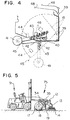
forklift vehicle 91 pushes large-scale cleaning vehicle 75 of the present invention. Asforklift vehicle 91 pushes large-scale cleaning vehicle 75, the rotation ofrear wheels 18 causes left and rightrotating brushes 14 to rotate. The rotation of rotatingbrush 14 collects debris toward the center of large-scale cleaning vehicle 75.Brush 17, which is also rotated by the rotation ofrear wheels 18, sweeps up the collected debris. Asbrush 17 sweeps up the collected debris, the swept debris is drawn todebris collection box 15 byfan 34, which is also rotated by the rotation ofrear wheels 18. Incasing 16, afilter 47 is attached to a position corresponding to the upper surface ofdebris collection box 15. Air containing the debris drawn in byfan 34 is cleaned byfilter 47, and the debris drops into debris collection box. The air which is drawn byfan 34, now free of debris, leavesfilter 47 and is dispersed outside via the open upper surface ofcasing 16. - Referring now to Figs. 1, 3a, and 3b, a fork-fitting
member 35 of large-scale cleaning vehicle 75 comprises: abox 36 into which the fork offorklift vehicle 91 is fitted and which has one of its side walls left open; and asupport plate 37 for mountingbox 36. The front ofsupport plate 37 and the front offrame 12 are rotatably connected by a pin. Fork-fittingmember 35 swings over side plates disposed on the left and right sides offrame 12. Also, a support plate is disposed onfork fitting member 35 across the width offrame 12 so thatfork fitting member 35 is prevented from arching upward. - Referring now to Figs. 1, 2, and 4, a
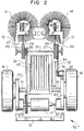
claw 45 is disposed on the open side ofdebris collecting box 15 toward sweepingbrush 17.Debris collecting box 15 is disposed withincasing 16 and attached to casing 16 so that it can swing freely around apin 40. The lower surface ofdebris collection box 15 is suspended by a hook-shapedratchet 39, and the upward and downward motions ofratchet 39 allowdebris collection box 15 to swing. -
Casters 41 are loosely inserted in the left and right gaps betweendebris collection box 15 andcasing 16.Casters 41 are attached so that they can pivot arounddebris collection box 15 andpin 42.Casters 41 are connected todebris collection box 15 via a coil spring so that upward tension is applied tocasters 41. Astopper 44 is disposed ondebris collection box 15 in order to keepcaster 41 at a fixed position as it is pulled up.Stopper 44 is disposed at a position that stopscaster 41 when its lower edge is slightly below (i.e. toward the ground) the bottom surface and claw 45 ofdebris collection box 15. Whendebris collection box 15 is pulled upward withratchet 39,stopper 44 pushescaster 41 downward. Ifratchet 39 is not pullingdebris collection box 15 upward, an upward force is acting oncaster 41 fromcoil spring 43. Referring specifically to Fig. 4, the force is applied clockwise. However, whenstopper 44 pushescaster 41 down to the fixed position, i.e. past the position wherecaster 41 andcoil spring 43 are parallel to each other,coil spring 43 applies a downward force tocaster 41. The force is applied counterclockwise.Stopper 46 is disposed ondebris collection box 15 so that whencaster 41 is being pulled it stops at a position where it is positioned roughly perpendicular to the ground. Thus, the lower end ofcaster 41 will always be further toward the ground than the bottom surface ofdebris collection box 15 andclaw 45. Thus, the bottom surface ofdebris collection box 15 and claw 45 are prevented from damage. - The following is a description of the embodiment of the present invention, wherein a rotating brush is attached so that it can swing freely.
- Referring to Fig. 5, large-
scale cleaning vehicle 75 pushed byforklift vehicle 91rotates rotating brush 14. Aframe 12 forms the upper section of the large-scale cleaning vehicle.Frame 12 is supported at three points by a pair ofrear wheels 18 and a singlefront wheel caster 19.Fork fitting member 35 is disposed onframe 12. The fork offorklift vehicle 91 is inserted intofork fitting member 35 to push large-scale cleaning vehicle 75 forward. - Referring now to Fig. 7, there is shown an enlarged perspective drawing of the main elements of large-
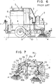
scale cleaning vehicle 75 of the present invention. Left and right rotatingbrush support plates 13 are attached downward below the left and right ends offrame 12. Upper andlower brackets 49 are fixed horizontally to the inner sides ofsupport plates 13. - A rotating
brush attachment member 50 is formed in the shape of a square "C". Rotatingbrush attachment member 50, to the front of which rotatingbrush 14 is attached pointing downward, is loosely inserted into upper andlower brackets 49. The base end of a connectingrod 51 is connected to rotatingbrush attachment member 50, and the end of connectingrod 51 is movably mounted into abolt 53 disposed toward the back of upper andlower brackets 49. Thus, rotatingbrush attachment member 50 and rotatingbrush 14 can be swung to the left and right aboutbolt 53. - Referring now also to Figs. 8 and 9,
openings lower brackets 49.Openings bolt 53 and are positioned at equivalent positions on upper andlower brackets 49. Holes 50a are also formed at corresponding positions in the upper and lower surfaces (i.e. the horizontal sides) of rotatingbrush attachment member 50. When hole 50a andhole 49a of are aligned, knockpin 54 is inserted and fitted through the aligned holes. Knockpin 54 fixesbrush attachment member 50 to rotatingbrush support plate 13. - When rotating
brush 14 is to be moved inward, knockpin 54 is disengaged from the aligned holes and rotatingbrush attachment member 50 is rotated inward aboutbolt 53 to align hole 50a andhole 49b. Then, knockpin 54 is inserted and fitted again to fixbrush attachment member 50 to rotatingbrush support plate 13. - A
primary drive pulley 55 is fixed to shaft 17a of sweepingbrush 17 disposed behindrear wheel 18. Drivenpulley 58 is attached in front of rotatingbrush attachment member 50 and serves to transfer the drive force to rotate rotatingbrush 14. The drive force from the rotation ofrear wheel 18 is transferred to rotatingbrush 14 viabelt 58, which bridgesprimary drive pulley 55 and drivenpulley 56. Referring momentarily to Fig. 9, atension pulley 57 is also shown. - Furthermore, the motion of rotating
brush 14 and rotatingbrush attachment member 50 causes drivenpulley 56 andtension pulley 57 to move. When this happens,belt 58 is prevented from becoming slack by disposing avertical rod 52 between the lower portion offrame 12 andbracket 49 and inward frombelt 58. - The following is a description of the foot lever for raising the rotating brush Referring to Fig. 1,
vehicle frame 12 of the cleaning vehicle is formed as a square and is supported at three points by a pair ofrear wheels 18 and asingle front wheel 19. - A
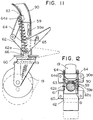
caster attachment leg 90 is attached downward at a central portion of the front ofvehicle frame 12. Ashaft 59 is inserted incaster attachment leg 90 from the bottom.Shaft 59 is fitted so that it can slide up and down and rotate freely.Front caster 19 is mounted downward at the lower portion ofshaft 59 and is fixed integrally to asupport plate 60, which forms a brim. - Referring to Fig. 10, there is shown a front-view drawing showing
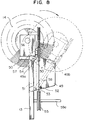
front wheel caster 19 and rotatingbrush 14 attached to the front part ofvehicle frame 12. A rotatingbrush 14 is attached facing down to each end ofvehicle frame 12, but only one rotating brush is shown in the drawing.Support plate 60, which is formed by overlapping two plates, andfront wheel caster 19 is rotatably mounted onlower support plate 60. A pair ofbrackets 61 is disposed on the upper surface ofupper support plate 60. - Referring now also to Fig. 11,
support plate 60 offront wheel caster 19 is fixed integrally to the lower surface ofshaft 59. A pair ofbrackets 61 is disposed on the upper surface ofsupport plate 60, which projects out from the perimeter ofshaft 59 like a brim. A bell-crank foot lever is movably mounted into these brackets with apin 62a.Foot lever 62 is U-shaped when viewed from the side. - One end of
foot lever 62 is connected to a connectingmember 63 via a connectingrod 64 and a connectingpin 64a. Connectingmember 63 is supported oncaster attachment leg 90. - A
tension spring 65 is disposed between a connectingpoint 64a and a connectingpoint 62a.Connecting point 64a is the connection between connectingmember 63 and connectingrod 64.Connecting point 62a is the connection between the bend infoot lever 67 andbracket 61. - Referring now to Fig. 12, to prevent rotation of
shaft 59, aninward projection 90a is formed on a section ofcaster attachment leg 90. Aflat end surface 59a is formed on a section ofshaft 59 to come into contact withinward projection 90a. - Referring again also to Fig. 11, the dotted line shows how the foot lever operates. When
foot lever 62 is kicked up or down,support plate 60, which is connected viabracket 61 tofoot lever 62, is moved up and down. Likewise,shaft 59 andfront wheel 19, which are fixed to supportplate 60, are also moved up and down. This causes rotatingbrush 14, which is integrally connected withcaster attachment leg 90 tovehicle frame 12, to move up and down. - The following is a description of the preferred embodiments of a large-scale trash removal device attached to a large-scale cleaning vehicle. Referring to Figs. 13-15 and 18-19, a large-scale
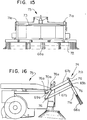
trash removal device 74 comprises: abrush 66a;arms support rods rod 70a; a vertical rod 71; a squeezingpiece 72; and a connectingrod 73. Referring to Fig. 14, large-scaletrash removal device 74, comprising these members, is attached to a large-scale cleaning vehicle 75 so that it projects toward the front of largescale cleaning vehicle 75. - Large-scale
trash removal device 74 and large-scale cleaning vehicle 75 are connected vialiftable arms shafts arm 67a andarm 67b are supported by supportingrods - The ends of
support rod 69a are fixed to large-scale cleaning vehicle 75 viashafts Arms rod 69a so that they can be lifted up and down.Arms support rod 69b are fixed toshafts 76c, 76d at the end opposite from the large-scale cleaning vehicle.Support rod 69b is fixed so that it overlaps withvertical rod 71a. -
Lower arm 67b is longer thanupper arm 67a, and ahooked hole 68 is disposed onlower arm 67b into which 76b is loosely inserted.Support 69b fixes the relative positioning ofarm 67a and one end ofarm 67b.Support arm 69a is fixed to large-scale cleaning vehicle 75. Thus, whenarms arm 67b to make it move to the right and up. -
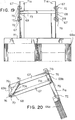
Arms 67a andarm 67b are also supported in a diagonal orientation by connectingrod 70a.Connecting rod 70a andarm 67a are rotatably attached aroundshalt 76e. Aslot 70b is disposed at a lower portion of connectingrod 70a, which supportsarms Shaft 76b is loosely inserted intoslot 70b. Since the relative positioning ofarm 67a and one end ofarm 67b is fixed bysupport rod 69b, connectingrod 70a is raised whenarms rod 70a. -
Vertical rod 71a on the right side andvertical rod 71a on the left side are connected in the shape of an "H" by connectingrod 73. The lower end of vertical rod 71 is opened downward. Vertical rod 71 is attached to a squeezingpiece 72, which is formed with a cavity oriented toward the large-scale cleaning vehicle on the side facing the ground. Abrush 66a is inserted into squeezingpiece 72. If anelastic plate 66b made from a rubber plate or the like is used,elastic plate 66b (not shown in Fig. 13-15 or 18-19) is inserted into squeezingpiece 72 in the same manner. -
Slots vertical rod 71a. By changing the fixing position betweenarms support rod 69b, it is possible to adjust the height ofbrush 66a. This makes it possible to have the brush position correspond with the height of the ground.Arms shafts 76c, 76d. - Referring to Figs. 16 and 20, when large-scale
trash removal device 74 is not being used, it is possible to draw it upward so thatbrush 66a is kept away from the ground. Whenarms shafts arm 67b is drawn diagonally, to the up and to the right in Fig. 20. The hooked section ofhooked hole 68 disposed onarm 67b is fitted withshaft 76b. This maintains the raised configuration. When large-scaletrash removal device 74 is to be lowered from the raised state,arm 67b is drawn up and the engagement between the hooked section ofhooked hole 68 and shaft 78b is disabled. This will cause large-scaletrash removal device 74 to return back to the ground from its own weight. - The description above covered the embodiment of large-scale
trash removal device 74. However, in another embodiment, there is noslot 71b disposed onvertical rod 71a. Thus, the height ofbrush 66a cannot be adjusted. Otherwise the structures of this embodiment are identical to those of the embodiment described above. - Referring to Fig. 17, in the large-scale
trash removal device 74, anelastic plate 66b made from a rubber plate is used instead ofbrush 66a. Otherwise the structures of this embodiment are identical to those of the above described embodiment. - Referring to the drawings, the following is a description of the large-scale trash removal device with a sprinkler device. Referring to Fig. 5, a
frame 12 forms the upper portion of large-scale cleaning vehicle 75 and is supported at three points by a pair ofrear wheels 18 and a single front-wheel caster 19. Rotating brushes 14 arc attached to the end of two rotatingbrush support plates 13, which are attached pointing downward to the front of the frame. The vehicle is moved forward by inserting a fork intofork fitting member 35, which is movably attached to the upper surface of the frame. - Referring to Figs. 21 and 22, a pair of
bases 79 is attached to the left and right sides ofupper surface 12a offrame 12, which forms the upper portion of large-scale cleaning vehicle 75. Awater tank 80 is mounted and fixed onbases 79. - A
hole 82 is formed toward the right end ofupper surface 12a of the frame. Awater pipe 81 is inserted in a water-tight manner intohole 82. Awater pipe 81 projects up fromhole 82. The upper end ofwater pipe 81 is inserted in a water-tight manner to the bottom ofwater tank 80. A prescribed number ofsprinkler pipes 83 continuous withwater pipe 81 is laid across the front of front-wheel caster 19, which supportsframe 12.Multiple nozzles 83a are disposed onsprinkler pipe 83, and acock valve 84 is attached towater pipe 81 to adjust the water flow. A left side ofwater pipes 83 is connected to aclosed pipe 85, such that water enteringwater pipes 83 must exit throughnozzles 83a. - The following is a description of the large-scale cleaning vehicle with a sound generating device. Referring to Fig. 5, a
frame 12 is supported by a pair ofrear wheels 18 and a single front-wheel caster 19. Rotatingbrush support plates 13 are attached facing down to the ends offrame 12 andsupport rotating brush 14. - Referring now also to Figs. 23 and 24, there is shown large-
scale cleaning vehicle 75 with asound generating device 91. Afork fitting member 35 is attached to frame 12.Fork fitting member 35 is able to move around ashaft 89, which supports front-wheel caster 19.Fork fitting member 35 comprises a fork-fittingsection 35a and ashaft 89, which are connected integrally via a connectingsection 35b. - An inner wall is disposed inside connecting
section 35b to form a sound generation chamber.Sound generating device 91, mounted in connectingsection 35b, comprises aspeaker 90 and an audio synthesizer IC or a melody IC.Speaker 90 is fixed so that it points toward a slit disposed on the side wall of connectingsection 35b. - A
sensor 93 is attached ontofork fitting section 35. Whensensor 93 detects the insertion or removal of the fork,sound generating device 91 is activated and plays back melodies or warnings such as "Now cleaning," "Please be careful". - The following is a list of advantages of the invention.
- 1. In the large-scale cleaning vehicle according to the present invention, it is possible to rotate rotating brushes, sweeping brushes, and fans without the use of an engine. The large-scale cleaning vehicle is also capable of tight maneuvers. Furthermore, the forklift operator can let out the debris collected in the debris collection box while still in the driver's seat. Also, the large-scale cleaning vehicle can be operated on uneven ground without damage resulting to the claw on the debris collection box or to the ground.
- 2. Also, if the width of the area to be cleaned is the width in which the large-scale cleaning vehicle can operate, the rotating brushes can be rotated and debris collection can be performed. Furthermore, the angle of the rotating brush support member can be changed so that the width between the rotating brushes is fixed to a prescribed width when collecting debris.
- 3. The rotating brushes can be raised when the large-scale cleaning vehicle is moving while the rotating brushes are not being used, or when the large-scale cleaning vehicle is stationary. Thus, since the ends of the rotating brushes are not in contact with the ground, they will not be deformed and debris collection can be performed over a long period while avoiding wear.
- 4. A foot-lever formed in the shape of a bell crank and the elastic force of a spring can be used to perform one-touch operation of the foot lever simply by kicking it down or up.
- 5. Large-scale trash that could not be removed with conventional large-scale cleaning vehicles can be pushed and removed. Also, when large-scale trash is not dispersed, it can be lifted up, and small-scale trash can be efficiently removed. Furthermore, the ground-contact height of the brush or an elastic plate made from a rubber plate or the like can be freely adjusted according to the unevenness of the ground.
- 6. Because water is sprinkled, the dust from the ground does not rise up, and the debris collection is made more efficient. Also, the operator does not breathe in dust, allowing a healthier environment. The removal of debris adhered to the ground is also made more easy by the sprinkled water. Furthermore, since the rotating brush brushes against the ground when it is wet with water, the ground is cleaned in addition to the debris being collected.
- 7. Cleaning work, which can become monotonous, is made more enjoyable and the cleaning operator's morale is improved. Also, since the safety of pedestrians is maintained through warnings, the operator can safely concentrate on the cleaning operation.
- Having described preferred embodiments of the invention with reference to the accompanying drawings, it is to be understood that the invention is not limited to those precise embodiments, and that various changes and modifications may be effected therein by one skilled in the art without departing from the scope or spirit of the invention as defined in the appended claims.
Claims (21)
- A large-scale cleaning vehicle pushed by a forklift vehicle comprising:a frame having roughly a cube shape;rotating brushes are attached downward at ends of a front portion of said frame;a rear wheel and a front wheel supporting said frame;a casing within said frame, said casing being roughly cube shaped and having a top surface and a rear side surface left open;a filter is connected to said top surface of said casing;a debris collection box is movably attached inside said casing, said debris collection box having a top surface and a rear side surface left open;a rotation of said rear wheel is transferred to said pair of rotating brushes disposed on the front of said large-scale cleaning vehicle, said rotation being transferred using a rotational transfer member;debris is swept toward a center and rear portion of a central portion of said large scale cleaning vehicle;said rotation of said rear wheel is also transferred to a sweeping brush disposed at the rear of said large-scale cleaning vehicle using another rotational transfer member;debris swept by said rotating brush disposed on the front of said large-scale cleaning vehicle is swept up by said sweeping brush;said rotation of said rear wheel is also transferred to a fan using a rotational transfer member;said fan drawing said swept-up debris toward said filter;air cleaned by said filter is sent outward from said top surface of said casing; andsaid debris is collected in said debris collection box disposed below said filter.
- A large-scale cleaning vehicle of claim 1, whereina lower surface of said debris collection box is suspended by a hooked portion of a hook-shaped ratchet attached to said casing so that it can move up and down;a wire is attached to an upper end of said ratchet to allow said debris collection box to move;casters are loosely inserted into left and right gaps between said debris collection box and said casing, and said casters are movably attached to said debris collection box;said debris collection box and said caster are connected by a coil spring; anda stopper is attached so that a lower edge of said caster is always kept at a position lower than a claw and a bottom surface of said debris collection surface, preventing damage to said claw and said bottom surface of said debris collection box.
- A large-scale cleaning vehicle according to claim 1, wherein:a fork fitting member is movably connected to another frame at said front of said frame of said large-scale cleaning vehicle, said fork fitting member comprising two cube-shaped boxes having one side wall left open, and a support plate connected to and on which is mounted said boxes.
- A large-scale cleaning vehicle comprising:a vehicle body frame is supported by a pair of rear wheels and a single front-wheel caster;a fork insertion member is movably attached to said frame;brackets for supporting rotating brush attachment members are attached pointing downward to the bottom of the ends of said frame;said rotating brush attachment member, to which said rotating brush is attached pointing downward, is attached integrally to a connecting rod;an end of said connecting rod is movably mounted to a back of said bracket for supporting said rotating brush attachment member;a plurality of holes is formed on said bracket and said rotating brush attachment member;prescribed holes are made continuous and a fixing pin is inserted through said holes; andon said bracket is disposed a vertical rod for applying tension to a belt disposed across pulleys for rotating said rotating brush.
- A large-scale cleaning vehicle as in claim 1 having a foot lever for raising a rotating brush, wherein:a hollow caster attachment leg is fixed onto a vehicle body frame so that it is pointing downward, said caster attachment leg being attached at a central position between rotating brushes attached downward from ends of said vehicle body frame at the front of a large-scale cleaning vehicle;a support plate on which is mounted a rotatable front-wheel caster is fixed to a lower end of a shaft;said shaft is inserted into a lower section of said caster attachment leg so that said shaft can slide up and down and can rotate;a bracket is disposed on said support plate and is movably mounted to a bent section of a foot lever shaped like a bell crank;one end of said foot lever is connected to said caster attachment leg via a connecting rod; anda tension spring connects a connecting point between said connecting rod and said caster attachment leg and a connecting point between said foot lever and said bracket.
- A large-scale trash removal device for attachment to a large-scale cleaning vehicle, comprising:a brush attached to said large-scale cleaning vehicle so that it can be raised or lowered, andsaid brush being mounted so that at a ground-contact surface, said brush is concave toward said large-scale cleaning vehicle.
- A large-scale trash removal device for large-scale cleaning vehicles comprising:an elastic plate brush made from a rubber plate is attached to said large-scale cleaning vehicle so that it can be raised or lowered, andsaid brush being mounted so that at a ground-contact surface, said brush is concave toward said large-scale cleaning vehicle.
- A large-scale trash removal device for large-scale cleaning vehicles as described in claim 6, wherein:a brush or an elastic plate material is attached so that its height can be adjusted.
- A large-scale cleaning vehicle with a water sprinkling device comprisinga vehicle body frame;a fork insertion member movably attached to said vehicle body frame supported by a pair of rear wheels and a single front wheel;a rotating brush support bracket is attached pointing downward on a bottom of said frame;a rotating brush attached to an end of said rotating brush support bracket;a water tank holding a volume of water mounted on said frame;a water sprinkler pipe is disposed across a front of said frame, said water sprinkler pipe having a plurality of nozzles; andsaid volume of water being connected to said water sprinkler pipe such that said water passes from said water tank through said water sprinkler pipe and out of said plurality of nozzles.
- A large-scale cleaning vehicle with a sound generating device comprising:a vehicle frame body;a fork insertion member movably attached to said vehicle body frame supported by a pair of rear wheels and a single front wheel;rotating brush support brackets attached pointing downward on the bottom of the ends of said frame; androtating brushes attached to an end of said brackets.
- A cleaning vehicle, comprising:a frame having a front end and a rear end;an insertion member pivotally connected at said front end of said frame, said insertion member being shaped to receive a connecting member from a second vehicle which supplies a motive force to said cleaning vehicle;said frame being supported by a rear wheel and a front wheel;a rotating brush assembly connected to said front end of said frame;at least one rotating brush rotatably connected to at least one rotating brush support plate, said at least one rotating brush support plate being pivotally connected to said rotating brush assembly, said at least one rotating brush support plate being pivotable between an outer position and an inner position to adjust a width of sweeping;a sweeping brush positioned toward a rear end of said frame;a debris collection box hingably connected at a bottom of said tray;a fan being operationally connected to said debris collection box such that rotation of said fan pulls debris swept by said sweeping brush into said debris collection box; andeach of said at least one rotating brush, said sweeping brush, and said fan being rotatably connected to said rear wheel such that said each of said at least one rotating; brush, said sweeping brush, and said fan rotates when said rear wheel is rotated.
- The cleaning vehicle of claim 11, wherein a vertical height of said rotating brush assembly is adjustable, said cleaning vehicle further comprising:said front wheel connected to a shaft;a hollow attachment leg on said frame receiving said shaft;a pedal pivotally connected to a lower portion of said shaft;said pedal also being connected to said hollow attachment leg;said pedal being movable between a first position and a second position;said first position corresponding to a lowered position of said rotating brush assembly where said at least one rotating brush contacts the ground on which the cleaning vehicle is standing; andsaid second position corresponding to an upper position of said rotating brush assembly where said at least one rotating brush is raised above the ground on which the cleaning vehicle is standing.
- The cleaning vehicle of claim 11, further including:a large scale trash removal brush mounted in front of said cleaning vehicle;said large scale trash removal brush being hingably mounted by two arms to said frame such that a height of said large scale trash removal brush is adjustable responsive to the height of the ground on which it rests.
- The cleaning vehicle of claim 13, further including:a hook insertable in one of said arms to hold said large scale trash removal brush in an upper position, above the ground.
- The cleaning vehicle of claim 13, wherein said large scale trash removal brush is one of a rubber or a plastic longitudinal strip.
- The cleaning vehicle of claim 11, further including a sprinkler assembly, wherein said sprinkler assembly further comprises:a water tank;water pipes horizontally connected accross said front end of said cleaning vehicle;said water pipes having a plurality of nozzles for directing; water to the ground below said cleaning vehicle.
- The cleaning vehicle of claim 11, further including an audible warning device.
- The cleaning device of claim 17, wherein said audible warning device includes:a sensor mounted in said insertion member having an output; anda sound generating device responsive to an output of said sensor.
- The cleaning device of claim 11, further including:casters pivotally and hingably connected to sides of said debris collection box; andsaid casters being arranged such that said casters contact the ground below said cleaning vehicle before said debris collection box does.
- The cleaning device of claim 11, further including:a vertically movable ratchet is connected to said frame;a bend in said ratchet being connected to a bottom of said debris collection box;another end of said ratchet being connected to a wire; andsaid ratchet being operable to release collected trash in said trach collection box responsive to a pulling of said wire.
- A cleaning vehicle, comprising:a frame having a front end and a rear end;an insertion member pivotally connected at said front end of said frame, said insertion member being shaped to receive a connecting member from a second vehicle which supplies a motive force to said cleaning vehicle.said frame being supported by a rear wheel and a front wheel;a rotating brush assembly connected to said front end of said frame;at least one rotating brush rotatably connected to at least one rotating brush support plate, said at least one rotating brush support plate being pivotally connected to said rotating brush assembly, said at least one rotating brush support plate being pivotable between an outer position and an inner position to adjust a width of sweeping;said rotating brush assembly being vertically adjustable between an upper position, where said at least one rotating brush is held above the ground below said cleaning machine, and a lower position, where said at least one rotating brush contacts the ground;a sweeping brush positioned toward a rear end of said frame;a debris collection box hingably connected at a bottom of said tray;a fan being operationally connected to said debris collection box such that rotation of said fan pulls debris swept by said sweeping brush into said debris collection box;each of said at least one rotating brush, said sweeping brush, and said fan being rotatably connected to said rear wheel such that said each of said at least one rotating brush, said sweeping brush, and said fan rotates when said rear wheel is rotated;a water sprinkler system, including a water tank connected to a nozzle assembly, mounted at said front end;an audible warning system responsive to a sensor mounted on said insertion member; anda large scale trash brush hingably mounted at said front end.
Applications Claiming Priority (22)
| Application Number | Priority Date | Filing Date | Title |
|---|---|---|---|
| JP11872896 | 1996-05-14 | ||
| JP11872896A JP2824570B2 (en) | 1996-05-14 | 1996-05-14 | Large sweeper |
| JP118728/96 | 1996-05-14 | ||
| JP118727/96 | 1996-05-14 | ||
| JP11872796A JP3657055B2 (en) | 1996-05-14 | 1996-05-14 | Clamp for lifting, clamp operating device and lock device used for the clamp |
| JP8138041A JP2764258B2 (en) | 1996-05-31 | 1996-05-31 | Foot lever for rotating brush pulling in large vacuum cleaner |
| JP13804196 | 1996-05-31 | ||
| JP138041/96 | 1996-05-31 | ||
| JP20693096 | 1996-08-06 | ||
| JP206930/96 | 1996-08-06 | ||
| JP8206930A JPH1046537A (en) | 1996-08-06 | 1996-08-06 | Large cleaning car with sprinkler device |
| JP222084/96 | 1996-08-23 | ||
| JP22208496A JP2881576B2 (en) | 1996-08-23 | 1996-08-23 | Large sweeper |
| JP22208496 | 1996-08-23 | ||
| JP34937596 | 1996-12-27 | ||
| JP349375/96 | 1996-12-27 | ||
| JP8349375A JP2995009B2 (en) | 1996-12-27 | 1996-12-27 | Large cleaning truck with sound generator |
| JP67909/97 | 1997-03-21 | ||
| JP6790997A JPH10258151A (en) | 1997-03-21 | 1997-03-21 | Selective numeral deciding device at numeral selecting type lottery ticket |
| JP6791097 | 1997-03-21 | ||
| JP9067910A JPH10266152A (en) | 1997-03-21 | 1997-03-21 | Large-sized waste removal device attached to large cleaning car |
| JP67910/97 | 1997-03-21 |
Publications (3)
| Publication Number | Publication Date |
|---|---|
| EP0807716A2 true EP0807716A2 (en) | 1997-11-19 |
| EP0807716A3 EP0807716A3 (en) | 1998-04-29 |
| EP0807716B1 EP0807716B1 (en) | 2003-07-23 |
Family
ID=27572596
Family Applications (1)
| Application Number | Title | Priority Date | Filing Date |
|---|---|---|---|
| EP97107835A Expired - Lifetime EP0807716B1 (en) | 1996-05-14 | 1997-05-14 | Large-scale cleaning vehicle |
Country Status (1)
| Country | Link |
|---|---|
| EP (1) | EP0807716B1 (en) |
Cited By (15)
| Publication number | Priority date | Publication date | Assignee | Title |
|---|---|---|---|---|
| KR20000058494A (en) * | 2000-06-03 | 2000-10-05 | 임항규 | Auto Broom |
| WO2009074629A1 (en) * | 2007-12-12 | 2009-06-18 | Etablissements Emily | Sweeper |
| CN104018452A (en) * | 2014-06-27 | 2014-09-03 | 怀远县路达公路养护有限公司 | Towed sweeper |
| CN104088241A (en) * | 2014-07-30 | 2014-10-08 | 芜湖爱瑞特环保科技有限公司 | Sweeping cleaning vehicle |
| CN107642061A (en) * | 2017-10-16 | 2018-01-30 | 厦门大学嘉庚学院 | A kind of sweeping vehicle for environmental sanitation and its application method |
| CN107724309A (en) * | 2017-10-25 | 2018-02-23 | 迟中焕 | Blowing and drawing type road cleaner |
| CN109056601A (en) * | 2018-08-07 | 2018-12-21 | 金寨县麻埠镇爱民保洁有限公司 | A kind of road cleaning Manual cleaning cart |
| CN109528103A (en) * | 2019-01-22 | 2019-03-29 | 苏州锐科兰电器有限公司 | Floor cleaning machine |
| CN109837850A (en) * | 2019-02-01 | 2019-06-04 | 南通绿能环保设备有限公司 | A kind of road sweeper being easily installed |
| CN110904897A (en) * | 2018-09-14 | 2020-03-24 | 王三保 | Double-wing sweeper |
| CN112502078A (en) * | 2020-11-30 | 2021-03-16 | 河南泽泰公路工程有限公司 | Municipal garden road leaf cleaning device |
| CN112807910A (en) * | 2020-12-25 | 2021-05-18 | 青岛百通路桥工程有限公司 | Automatic cleaning equipment for spraying, dust collecting and cleaning in construction site |
| CN115535896A (en) * | 2022-09-30 | 2022-12-30 | 中国建筑第五工程局有限公司 | A safe and energy-saving construction hoist |
| CN115769996A (en) * | 2021-09-06 | 2023-03-10 | 追觅创新科技(苏州)有限公司 | Cleaning device and cleaning equipment |
| US12490878B2 (en) | 2021-09-06 | 2025-12-09 | Dreame Innovation Technology (Suzhou) Co., Ltd. | Cleaning device, cleaning mechanism, sweeper and cleaning apparatus |
Families Citing this family (3)
| Publication number | Priority date | Publication date | Assignee | Title |
|---|---|---|---|---|
| CN103669264B (en) * | 2013-12-04 | 2015-12-02 | 冯政 | The manufacture of rope skipping formula side sweeping device, installation and using method |
| CN108937777A (en) * | 2018-07-24 | 2018-12-07 | 赵笑妍 | Class's instruments of labour fixator |
| CN112653981A (en) * | 2020-12-17 | 2021-04-13 | 柳琴琴 | Think political affairs teaching and use megaphone |
Family Cites Families (5)
| Publication number | Priority date | Publication date | Assignee | Title |
|---|---|---|---|---|
| DE2150496A1 (en) * | 1971-10-09 | 1973-04-12 | Croker Edgar Alfred | MOBILE CLEANING MACHINE |
| GB1524953A (en) * | 1975-12-02 | 1978-09-13 | Leeford London Ltd | Implement mounting assembly |
| AU533030B2 (en) * | 1981-03-27 | 1983-10-27 | Kyle, A.H. | Road sweeper |
| AU586891B2 (en) * | 1985-10-01 | 1989-07-27 | Forklift Engineering Australia Pty. Ltd. | Fork mounted sweeper |
| DE3673406D1 (en) * | 1986-04-21 | 1990-09-13 | Schmidt Alfred Ing Gmbh | SELF-RECOVERY SWEEPER. |
-
1997
- 1997-05-14 EP EP97107835A patent/EP0807716B1/en not_active Expired - Lifetime
Cited By (20)
| Publication number | Priority date | Publication date | Assignee | Title |
|---|---|---|---|---|
| KR20000058494A (en) * | 2000-06-03 | 2000-10-05 | 임항규 | Auto Broom |
| WO2009074629A1 (en) * | 2007-12-12 | 2009-06-18 | Etablissements Emily | Sweeper |
| FR2925081A1 (en) * | 2007-12-12 | 2009-06-19 | Emily Soc Par Actions Simplifi | SWEEPER |
| CN104018452A (en) * | 2014-06-27 | 2014-09-03 | 怀远县路达公路养护有限公司 | Towed sweeper |
| CN104088241A (en) * | 2014-07-30 | 2014-10-08 | 芜湖爱瑞特环保科技有限公司 | Sweeping cleaning vehicle |
| CN107642061A (en) * | 2017-10-16 | 2018-01-30 | 厦门大学嘉庚学院 | A kind of sweeping vehicle for environmental sanitation and its application method |
| CN107642061B (en) * | 2017-10-16 | 2023-11-03 | 厦门大学嘉庚学院 | Sanitation street sweeper and application method thereof |
| CN107724309A (en) * | 2017-10-25 | 2018-02-23 | 迟中焕 | Blowing and drawing type road cleaner |
| CN109056601A (en) * | 2018-08-07 | 2018-12-21 | 金寨县麻埠镇爱民保洁有限公司 | A kind of road cleaning Manual cleaning cart |
| CN110904897A (en) * | 2018-09-14 | 2020-03-24 | 王三保 | Double-wing sweeper |
| CN109528103B (en) * | 2019-01-22 | 2023-09-15 | 苏州锐科兰电器有限公司 | Floor mopping machine |
| CN109528103A (en) * | 2019-01-22 | 2019-03-29 | 苏州锐科兰电器有限公司 | Floor cleaning machine |
| CN109837850A (en) * | 2019-02-01 | 2019-06-04 | 南通绿能环保设备有限公司 | A kind of road sweeper being easily installed |
| CN109837850B (en) * | 2019-02-01 | 2024-02-20 | 南通绿能环保设备有限公司 | A sweeper that is easy to install |
| CN112502078A (en) * | 2020-11-30 | 2021-03-16 | 河南泽泰公路工程有限公司 | Municipal garden road leaf cleaning device |
| CN112807910A (en) * | 2020-12-25 | 2021-05-18 | 青岛百通路桥工程有限公司 | Automatic cleaning equipment for spraying, dust collecting and cleaning in construction site |
| CN115769996A (en) * | 2021-09-06 | 2023-03-10 | 追觅创新科技(苏州)有限公司 | Cleaning device and cleaning equipment |
| CN115769996B (en) * | 2021-09-06 | 2023-11-07 | 追觅创新科技(苏州)有限公司 | Cleaning device and cleaning equipment |
| US12490878B2 (en) | 2021-09-06 | 2025-12-09 | Dreame Innovation Technology (Suzhou) Co., Ltd. | Cleaning device, cleaning mechanism, sweeper and cleaning apparatus |
| CN115535896A (en) * | 2022-09-30 | 2022-12-30 | 中国建筑第五工程局有限公司 | A safe and energy-saving construction hoist |
Also Published As
| Publication number | Publication date |
|---|---|
| EP0807716A3 (en) | 1998-04-29 |
| EP0807716B1 (en) | 2003-07-23 |
Similar Documents
| Publication | Publication Date | Title |
|---|---|---|
| US5987699A (en) | Large-scale cleaning vehicle | |
| EP0807716B1 (en) | Large-scale cleaning vehicle | |
| AU741959B2 (en) | Large scale cleaning vehicle | |
| US5265805A (en) | Rotary lance cleaning apparatus | |
| US5367741A (en) | Vacuum cleaner with improved assembly | |
| JP4515500B2 (en) | Tool for surface treatment equipment | |
| CA1269211A (en) | Vaccuum refuse collector | |
| US3358316A (en) | Suction cleaner | |
| EP0803224B2 (en) | Nozzle arrangement for a self-guiding vacuum cleaner | |
| US5208940A (en) | Floor dryer and warning device | |
| CA2274437C (en) | Storage system for vacuum pickup hose | |
| US4036346A (en) | Coin operated vacuum apparatus | |
| US5255411A (en) | Lift-off mechanism for an upright vacuum cleaner | |
| JP3674039B2 (en) | Cyclone vacuum cleaner | |
| CN111631058A (en) | A kind of mulching film equipment for agricultural planting | |
| US6098242A (en) | Upright vacuum cleaner | |
| JP2787436B2 (en) | Automatic cleaning device for heat exchanger of ceiling mounted air conditioner | |
| JP2832687B2 (en) | Cleaning device for heat exchanger of ceiling mounted air conditioner | |
| JP2610131B2 (en) | Filter device for pulse jet type dust collector | |
| GB2152362A (en) | Suction cleaning apparatus | |
| JP2000175563A (en) | Sulky type machine for cleaning surface of lawn | |
| US3676891A (en) | Vacuum machine for street cleaning | |
| US3805319A (en) | Vacuum cleaner suction tool with movable nozzles for cleaning deep pile shag rugs | |
| JPH04163240A (en) | Large scavenging cart | |
| JPH085368B2 (en) | Vacuum cleaner for cleaning the interior of automobiles |
Legal Events
| Date | Code | Title | Description |
|---|---|---|---|
| PUAI | Public reference made under article 153(3) epc to a published international application that has entered the european phase |
Free format text: ORIGINAL CODE: 0009012 |
|
| AK | Designated contracting states |
Kind code of ref document: A2 Designated state(s): BE CH DE FR GB IT LI NL |
|
| PUAL | Search report despatched |
Free format text: ORIGINAL CODE: 0009013 |
|
| AK | Designated contracting states |
Kind code of ref document: A3 Designated state(s): BE CH DE FR GB IT LI NL |
|
| 17P | Request for examination filed |
Effective date: 19981023 |
|
| 17Q | First examination report despatched |
Effective date: 20010423 |
|
| GRAH | Despatch of communication of intention to grant a patent |
Free format text: ORIGINAL CODE: EPIDOS IGRA |
|
| GRAH | Despatch of communication of intention to grant a patent |
Free format text: ORIGINAL CODE: EPIDOS IGRA |
|
| GRAA | (expected) grant |
Free format text: ORIGINAL CODE: 0009210 |
|
| AK | Designated contracting states |
Designated state(s): BE CH DE FR GB IT LI NL |
|
| PG25 | Lapsed in a contracting state [announced via postgrant information from national office to epo] |
Ref country code: NL Free format text: LAPSE BECAUSE OF FAILURE TO SUBMIT A TRANSLATION OF THE DESCRIPTION OR TO PAY THE FEE WITHIN THE PRESCRIBED TIME-LIMIT Effective date: 20030723 Ref country code: LI Free format text: LAPSE BECAUSE OF FAILURE TO SUBMIT A TRANSLATION OF THE DESCRIPTION OR TO PAY THE FEE WITHIN THE PRESCRIBED TIME-LIMIT Effective date: 20030723 Ref country code: CH Free format text: LAPSE BECAUSE OF FAILURE TO SUBMIT A TRANSLATION OF THE DESCRIPTION OR TO PAY THE FEE WITHIN THE PRESCRIBED TIME-LIMIT Effective date: 20030723 Ref country code: BE Free format text: LAPSE BECAUSE OF FAILURE TO SUBMIT A TRANSLATION OF THE DESCRIPTION OR TO PAY THE FEE WITHIN THE PRESCRIBED TIME-LIMIT Effective date: 20030723 |
|
| REG | Reference to a national code |
Ref country code: GB Ref legal event code: FG4D |
|
| REG | Reference to a national code |
Ref country code: CH Ref legal event code: EP |
|
| REF | Corresponds to: |
Ref document number: 69723614 Country of ref document: DE Date of ref document: 20030828 Kind code of ref document: P |
|
| NLV1 | Nl: lapsed or annulled due to failure to fulfill the requirements of art. 29p and 29m of the patents act | ||
| REG | Reference to a national code |
Ref country code: CH Ref legal event code: PL |
|
| ET | Fr: translation filed | ||
| PLBE | No opposition filed within time limit |
Free format text: ORIGINAL CODE: 0009261 |
|
| STAA | Information on the status of an ep patent application or granted ep patent |
Free format text: STATUS: NO OPPOSITION FILED WITHIN TIME LIMIT |
|
| 26N | No opposition filed |
Effective date: 20040426 |
|
| PGFP | Annual fee paid to national office [announced via postgrant information from national office to epo] |
Ref country code: DE Payment date: 20120529 Year of fee payment: 16 |
|
| PGFP | Annual fee paid to national office [announced via postgrant information from national office to epo] |
Ref country code: GB Payment date: 20120525 Year of fee payment: 16 Ref country code: FR Payment date: 20120607 Year of fee payment: 16 |
|
| PGFP | Annual fee paid to national office [announced via postgrant information from national office to epo] |
Ref country code: IT Payment date: 20120524 Year of fee payment: 16 |
|
| GBPC | Gb: european patent ceased through non-payment of renewal fee |
Effective date: 20130514 |
|
| PG25 | Lapsed in a contracting state [announced via postgrant information from national office to epo] |
Ref country code: DE Free format text: LAPSE BECAUSE OF NON-PAYMENT OF DUE FEES Effective date: 20131203 |
|
| PG25 | Lapsed in a contracting state [announced via postgrant information from national office to epo] |
Ref country code: IT Free format text: LAPSE BECAUSE OF NON-PAYMENT OF DUE FEES Effective date: 20130514 |
|
| REG | Reference to a national code |
Ref country code: DE Ref legal event code: R119 Ref document number: 69723614 Country of ref document: DE Effective date: 20131203 |
|
| REG | Reference to a national code |
Ref country code: FR Ref legal event code: ST Effective date: 20140131 |
|
| PG25 | Lapsed in a contracting state [announced via postgrant information from national office to epo] |
Ref country code: GB Free format text: LAPSE BECAUSE OF NON-PAYMENT OF DUE FEES Effective date: 20130514 |
|
| PG25 | Lapsed in a contracting state [announced via postgrant information from national office to epo] |
Ref country code: FR Free format text: LAPSE BECAUSE OF NON-PAYMENT OF DUE FEES Effective date: 20130531 |