EP0807705B1 - Improved industrial-use sewing machine adapted to perform two sequential seams, and to vary either leftwardly or rightwardly the stitch felling direction - Google Patents
Improved industrial-use sewing machine adapted to perform two sequential seams, and to vary either leftwardly or rightwardly the stitch felling direction Download PDFInfo
- Publication number
- EP0807705B1 EP0807705B1 EP97830214A EP97830214A EP0807705B1 EP 0807705 B1 EP0807705 B1 EP 0807705B1 EP 97830214 A EP97830214 A EP 97830214A EP 97830214 A EP97830214 A EP 97830214A EP 0807705 B1 EP0807705 B1 EP 0807705B1
- Authority
- EP
- European Patent Office
- Prior art keywords
- sewing machine
- cloth
- parts
- seamed
- sewing
- Prior art date
- Legal status (The legal status is an assumption and is not a legal conclusion. Google has not performed a legal analysis and makes no representation as to the accuracy of the status listed.)
- Expired - Lifetime
Links
- 238000009958 sewing Methods 0.000 title claims description 87
- 239000004744 fabric Substances 0.000 claims description 78
- 238000004826 seaming Methods 0.000 claims description 16
- 238000005452 bending Methods 0.000 claims description 10
- 230000033001 locomotion Effects 0.000 description 3
- 230000005540 biological transmission Effects 0.000 description 2
- 238000011144 upstream manufacturing Methods 0.000 description 2
- 239000011248 coating agent Substances 0.000 description 1
- 238000000576 coating method Methods 0.000 description 1
- 230000008878 coupling Effects 0.000 description 1
- 238000010168 coupling process Methods 0.000 description 1
- 238000005859 coupling reaction Methods 0.000 description 1
- 238000006073 displacement reaction Methods 0.000 description 1
- 238000004519 manufacturing process Methods 0.000 description 1
- 238000012986 modification Methods 0.000 description 1
- 230000004048 modification Effects 0.000 description 1
- 230000001360 synchronised effect Effects 0.000 description 1
Images


Classifications
-
- D—TEXTILES; PAPER
- D05—SEWING; EMBROIDERING; TUFTING
- D05B—SEWING
- D05B35/00—Work-feeding or -handling elements not otherwise provided for
- D05B35/02—Work-feeding or -handling elements not otherwise provided for for facilitating seaming; Hem-turning elements; Hemmers
Definitions
- the present invention relates to an improved industrial-use sewing machine adapted to perform two sequential seams, and to vary either leftwardly or rightwardly the stitch felling direction.
- This seaming operation usually consists of coupling to one another by a first seam, two parts of a cloth article to be seamed, and then bending the thus seamed parts, under either one or the other of the two portions of the cloth article extending from the two seamed parts of borders.
- Prior industrial sewing machines for performing the above mentioned operations conventionally operate in two subsequent operating steps, i.e. by using two different sewing machines, or by using a single sewing machine which, however, requires that several parts of the machine be replaced, depending on a leftwardly or rightwardly felling operation to be performed, or depending on the seamed cloth article parts seamed by the first seaming operation be bent under either one or the other of the two portions of the cloth article seamed at the two mentioned parts of borders.
- the aim of the present invention is to overcome the above mentioned drawback, by providing an improved industrial use sewing machine which is specifically designed for performing two immediately sequential seams, with the additional capability of changing the felling direction, either rightwardly or leftwardly, without requiring any replacing or fitting operations.
- a main object of the present invention is to provide such a sewing machine which, since it does not require any fitting operations for performing felling seaming operation, independently from the direction of the latter, provides a very high production yield, while reducing to a minimum the operation cost.
- Another object of the present invention is to provide such a sewing machine which is very safe and reliable in operation.
- Yet another object of the present invention is to provide such a sewing machine providing very accurate sequential seams, independently from the felling operation direction.
- an industrial-use sewing machine adapted to perform two sequential seams, and to vary either leftwardly or rightwardly the stitch felling direction
- said sewing machine comprises two sewing units, respectively a horizontal needle bar sewing unit and a vertical needle bar sewing unit, sequentially arranged along a cloth article feeding direction, along said cloth article feeding direction being moreover provided, under a cloth article bearing panel, a first guide defining a first passage for the two parts or borders of the cloth article to be seamed, which parts can be mutually arranged in a facing relationship on a substantially vertical plane, near the horizontal needle bar, and a second guide, arranged between said horizontal needle bar sewing unit and said vertical needle bar sewing unit, said second guide defining a second passage for the two parts of said cloth article, seamed by said horizontal needle bar sewing unit, and being provided moreover with means for bending said two seamed cloth article parts, in a direction transversal of
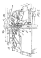
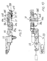
- the sewing machine according to the present invention which has been generally indicated by the reference number 1, comprises two sewing units, respectively a horizontal needle bar sewing unit 2 and a vertical needle bar central sewing unit 3, which are sequentially arranged, or cascade arranged, along the cloth article to be seamed feeding direction 4.
- the sewing units 2 and 3 can comprise two sewing units, respectively of a horizontal needle bar type and a vertical needle bar type, of conventional type, for example of the type comprising a main shaft 5, rotatively driven about its rotary axis, for example by an electric motor which, through a suitable transmission, including, for example, driving belts 6 and 7, drives two driven shafts 8 and 9 which, in turn, by known types of linkage and cam systems, which have been only partially shown in the figures of the accompanying drawings, will drive the horizontal needle bar 10 of the sewing unit 2 and the vertical needle bar 11 of the sewing unit 3.
- a suitable transmission including, for example, driving belts 6 and 7, drives two driven shafts 8 and 9 which, in turn, by known types of linkage and cam systems, which have been only partially shown in the figures of the accompanying drawings, will drive the horizontal needle bar 10 of the sewing unit 2 and the vertical needle bar 11 of the sewing unit 3.
- the two driven shafts 8 and 9 instead of being coupled to a single and same main shaft 5, can also be driven by individual electric motors, suitable synchronized with one another so as to provide a desired timing of the driving of the horizontal needle bar 10 with the vertical needle bar 11, as well as of the several component elements of the two sewing units 2 and 3, so as to progressively cause the cloth article to be seamed to advance along the cloth article feeding direction 4.
- the sewing unit 2 is preferably arranged under a cloth article bearing panel 12, which is substantially horizontally arranged, for the two parts or borders 13a and 13b of the cloth article to be seamed to one another.
- the bearing panel 12 is constituted by covering plates 14 and 15, having any suitable configurations, which are affixed to the bearing framework of the sewing machine.
- the feeding of the cloth article to be seamed along the feeding direction 4 is obtained, in a per se known manner, for example by using feeding grippers, conventionally included in conventional horizontal needle bar sewing units and vertical needle bar sewing units.
- the horizontal needle bar 10 can be provided with either one or more sewing needles 16, which are driven by the driven shaft 8, with a reciprocating translation motion along a substantially horizontal direction and transversal of the feeding direction 4.
- the needle or needles 16 cooperate with one or more crochets, not shown in the drawings, of conventional types, in order to form the seaming stitches.
- the sewing machine comprises moreover, near the working region of the horizontal needle bar 10, a first guide defining, in parallel to the feeding direction 4, a first passage 18 for the two parts or borders 20a and 20b of the cloth portions 13a and 13b to be seamed, which parts are arranged with a mutually facing relationship in a substantially vertical plane.
- the first guide 17 comprises a needle plate 21, defining a bearing surface, which is substantially vertical and parallel to said feeding direction 4, for the two cloth parts or borders 20a and 20b and a foot element 22, facing the bearing plane or surface defined by the needle plate 21.
- the needle plate 21 and the foot element 22 define therebetween a passage 18 for the two cloth parts or borders 20a and 20b.
- the foot element 22 can swing about a vertical axis 23, which is laterally spaced from the needle plate 21, away from the needle plate 18 and against the biassing of a biassing spring 24, so as to fit the different thicknesses of the cloth parts 20a and 20b.
- the needle plate 21 can be formed passage means for the cloth article feeding grippers, as the cloth article is seamed.
- the covering plates 14 and 15, which define the bearing panel 12 for the cloth article to be seamed, also define the inlet of the first guide 17, which inlet substantially comprises two side walls 25a and 25b, which are progressively driven toward one another, according to the feeding direction 4, so as to greatly facilitate the introduction of the cloth parts 20a and 20b, in a substantially vertical direction, inside the passage 18.
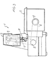
- the sewing machine according to the present invention comprises moreover a second guide 30, which is arranged in the machine region between the horizontal needle bar 10 and the vertical needle bar 11, along the feeding direction 4.
- the second guide 30 defines a second passage 31 for the two cloth parts 20a and 20b, seamed to one another by the sewing unit 2, and said second guide is provided with bending means 32 for bending the two cloth parts 20a and 20b in a cross direction with respect to the mentioned feeding direction 4.
- the following sewing unit 3 can perform a felling seaming operation of the two cloth parts 20a and 20b under either one or the other of the cloth portions 13a and 13b, depending on a rightwardly or leftwardly felling operation to be performed.
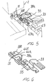
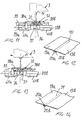
- the second guide 30 comprises a supporting arm element 33, which is connected to the sewing machine supporting framework and which slidably supports, along a direction substantially perpendicular to the feeding direction 4, a plate-like element 35, in which is defined a guide groove 36 for the two cloth parts 20a and 20b.
- a cut-out 37 which extends at the bottom the guide groove or channel 36.
- top small plates 38a and 38b which are mutually facing along the feeding direction 4 and which define therebetween the second passage 31.
- the top small plates 38a and 38b are connected to further small plates 39a and 39b which can slide either toward one another or away from one another, i.e. transversely of the feeding direction 4, in a sliding seat defined by a portion 40 of the supporting arm element 33 and by further bottom small plates 41a and 41b which are connected to the portion 40.
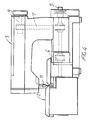
- the plate-like element 35 in which is defined said guide channel or groove 36, can be driven, transversely of the feeding direction 4, by a pneumatic cylinder 43, which has a cylinder body pivoted to the sewing machine framework and the stem rod 43a of the piston of which operates on the plate-like element 35, as is shown in a more clearly manner in figures 7 and 8.
- the small plates 38a and 38b are provided, on the end portions thereof facing the sewing unit 2, with lead-in bent portions 44a and 44b for the cloth parts 20a and 20b.
- the sewing unit 2 is preferably mounted on a slide, which can be controllably driven, for example by a pneumatic cylinder provided with limit elements, or by a nut-nutscrew assembly, in a direction transversal of the feeding direction 4, with respect the sewing unit 2.
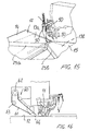
- the subject sewing machine comprises moreover pneumatic means for allowing the cloth portions 13a and 13b to be held properly spread apart on the bearing panel 12, said portions 13a and 13b extending from the two cloth parts 20a and 20b being seamed during the felling seaming operation.
- the above mentioned pneumatic means comprise pressurized air jet delivery nozzle 50 which are supported, immediately upstream of the working region of the vertical needle bar 11, and which are faced to the top of the bearing panel 12, so as to cause the cloth portions 13a and 13b to be held spread apart on said bearing panel 12, during the seaming operation.
- entraining means Downstream of the vertical needle bar 11, according to the feeding direction 14, are provided entraining means for entraining or driving the seamed cloth article, said entraining or driving means being indicated by the reference number 60.
- the mentioned driving means in particular, comprise a driving belt 61 entrained about a driving pulley 62 and two transmission pulleys 63 and 64, as well as a further tension pulley 65, according to a closed loop, extending, at least for a portion thereof, near the bearing panel 12, so as to engage by the top face thereof with the cloth article, upon seaming thereof, in order to cooperate with said grippers for causing said cloth article to be fed along the feeding direction 4.
- the two cloth parts or borders 20a and 20b of the cloth portions 13a and 13b to be seamed are introduced by the operator, in a mutually facing relationship in a substantially vertical plane, into the first passage 18 defined by the first guide 17.
- the thus engaged cloth parts 20a and 20b are driven along the feeding direction 4 and are subjected to the first seamed operation, performed by the horizontal needle bar 10.
- the thus seamed cloth parts 20a and 20b will enter the second passage 31 of the second guide 30, the end portions of the two cloth parts 20a and 20b being arranged in the guide channel 36.
- a corresponding displacement or driving movement is also applied to the seaming or sewing unit 3 which will perform, by means of the vertical needle bar 11, a felling seaming operation 70, as is clearly shown in figure 12.
- the plate-like element 35 will be driven, by the mentioned driving pneumatic cylinder 43, in an opposite direction, so as to cause the cloth parts 20a and 20b to be bent under the cloth portion 13a to be affixed to this portion by the seam performed by the sewing unit 3, which will be displaced or driven transversely of the cloth article feeding direction 4 in the same direction as the driving direction applied to the plate-like element 35 in order to perform the felling seam 71, as clearly shown in figure 14.
- a sewing machine which is specifically designed for performing either a rightwardly or leftwardly felling seaming operation, without requiring any replacing operations on parts of the sewing machine and, accordingly, without interrupting the operation of the sewing machine.
Landscapes
- Engineering & Computer Science (AREA)
- Textile Engineering (AREA)
- Sewing Machines And Sewing (AREA)
Applications Claiming Priority (2)
| Application Number | Priority Date | Filing Date | Title |
|---|---|---|---|
| IT96MI000988A IT1283025B1 (it) | 1996-05-16 | 1996-05-16 | Macchina da cucire perfezionata per uso industriale in grado di ese- guire due cuciture in sequenza immediata, con la possibilita' di vari- |
| ITMI960988 | 1996-05-16 |
Publications (3)
| Publication Number | Publication Date |
|---|---|
| EP0807705A2 EP0807705A2 (en) | 1997-11-19 |
| EP0807705A3 EP0807705A3 (en) | 1998-03-18 |
| EP0807705B1 true EP0807705B1 (en) | 2002-08-07 |
Family
ID=11374274
Family Applications (1)
| Application Number | Title | Priority Date | Filing Date |
|---|---|---|---|
| EP97830214A Expired - Lifetime EP0807705B1 (en) | 1996-05-16 | 1997-05-09 | Improved industrial-use sewing machine adapted to perform two sequential seams, and to vary either leftwardly or rightwardly the stitch felling direction |
Country Status (4)
| Country | Link |
|---|---|
| EP (1) | EP0807705B1 (it) |
| JP (1) | JPH1043450A (it) |
| DE (1) | DE69714510D1 (it) |
| IT (1) | IT1283025B1 (it) |
Families Citing this family (3)
| Publication number | Priority date | Publication date | Assignee | Title |
|---|---|---|---|---|
| CN107130370B (zh) * | 2017-06-08 | 2023-01-20 | 际华橡胶工业有限公司 | 一种用于鞋后帮缝制的批缝器 |
| CN112746399A (zh) * | 2019-10-30 | 2021-05-04 | 精机机械厂股份有限公司 | 缝纫机的缝骨翻折装置 |
| CN111424386B (zh) * | 2020-04-07 | 2021-10-22 | 建德市恒欣家纺有限公司 | 一种纺织用缝纫机 |
Family Cites Families (3)
| Publication number | Priority date | Publication date | Assignee | Title |
|---|---|---|---|---|
| US2176643A (en) * | 1938-01-31 | 1939-10-17 | Man Sew Pinking Attachment Cor | Method of making french seams |
| IT1246756B (it) * | 1990-12-28 | 1994-11-26 | Macpi Pressing Div | Macchina da cucire, per uso industriale, a struttura perfezionata, atta a permettere l'esecuzione sumultanea di piu' cuciture, di tipo differenziato. |
| IT1256321B (it) * | 1992-11-20 | 1995-11-30 | Rimoldi Srl | Metodo e macchina per l'esecuzione di cuciture su lembi di tessuti, e cucitura ottenuta |
-
1996
- 1996-05-16 IT IT96MI000988A patent/IT1283025B1/it active IP Right Grant
-
1997
- 1997-05-09 EP EP97830214A patent/EP0807705B1/en not_active Expired - Lifetime
- 1997-05-09 DE DE69714510T patent/DE69714510D1/de not_active Expired - Lifetime
- 1997-05-15 JP JP9125125A patent/JPH1043450A/ja active Pending
Also Published As
| Publication number | Publication date |
|---|---|
| EP0807705A2 (en) | 1997-11-19 |
| ITMI960988A0 (it) | 1996-05-16 |
| ITMI960988A1 (it) | 1997-11-16 |
| DE69714510D1 (de) | 2002-09-12 |
| JPH1043450A (ja) | 1998-02-17 |
| EP0807705A3 (en) | 1998-03-18 |
| IT1283025B1 (it) | 1998-04-03 |
Similar Documents
| Publication | Publication Date | Title |
|---|---|---|
| US5588384A (en) | Method and apparatus of folding opposite ends of a piece of tape | |
| US4068603A (en) | Apparatus for feeding material for forming a double tuck on the cut edges thereof | |
| CN110662862B (zh) | 遮布的缝边装置 | |
| US4572094A (en) | Sewing machine with workpiece differential transport device | |
| CA2617303A1 (en) | Device and method for handling tubular knitted articles, such as stockings and socks or the like | |
| EP0807705B1 (en) | Improved industrial-use sewing machine adapted to perform two sequential seams, and to vary either leftwardly or rightwardly the stitch felling direction | |
| US4043283A (en) | Sewing apparatus employing twin needles | |
| US4459733A (en) | Method and devices for assembly of helixes into face structures | |
| JP2003053080A (ja) | 上糸クランプ・カッターを有するミシン | |
| US4296696A (en) | Device for producing sewing seam patterns of stitch groups | |
| US4173191A (en) | Sewing unit with sectionwise shiftable clamping device | |
| CN211079553U (zh) | 一种医用防护服用四线机 | |
| US5931108A (en) | Process and automatic sewing machine for sewing a flap with a rough closing edge and a pocket on a fabric part in one operation | |
| US6105523A (en) | Belt-loop supply apparatus | |
| US6095070A (en) | Driving device for feeding material to be sewn in a sewing machine | |
| EP0494052B1 (en) | Industrial sewing machine for simultaneously making different seaming patterns | |
| EP0353208B1 (en) | Industrial sewing machine for simultaneously performing a plurality of improved seaming lines | |
| KR20080088436A (ko) | 단추 구멍 사뜨기 재봉틀 | |
| JP3392712B2 (ja) | 生地素材にシームを作るための方法と装置 | |
| JP4069268B2 (ja) | ベルトループ供給装置 | |
| US5269241A (en) | Industrial sewing machine for simultaneously making different seaming patterns | |
| US4688500A (en) | Device for holding a fabric in blind stich sewing | |
| CN212197746U (zh) | 收料机构及智能袖口罗纹机 | |
| CN220703991U (zh) | 下料机构 | |
| CN218842550U (zh) | 一种缝纫机上对裤子上腰折边机构 |
Legal Events
| Date | Code | Title | Description |
|---|---|---|---|
| PUAI | Public reference made under article 153(3) epc to a published international application that has entered the european phase |
Free format text: ORIGINAL CODE: 0009012 |
|
| AK | Designated contracting states |
Kind code of ref document: A2 Designated state(s): DE ES FR GB |
|
| PUAL | Search report despatched |
Free format text: ORIGINAL CODE: 0009013 |
|
| AK | Designated contracting states |
Kind code of ref document: A3 Designated state(s): DE ES FR GB |
|
| 17P | Request for examination filed |
Effective date: 19980714 |
|
| AKX | Designation fees paid |
Free format text: DE ES FR GB |
|
| RBV | Designated contracting states (corrected) |
Designated state(s): DE ES FR GB |
|
| 17Q | First examination report despatched |
Effective date: 20000921 |
|
| GRAG | Despatch of communication of intention to grant |
Free format text: ORIGINAL CODE: EPIDOS AGRA |
|
| GRAG | Despatch of communication of intention to grant |
Free format text: ORIGINAL CODE: EPIDOS AGRA |
|
| GRAH | Despatch of communication of intention to grant a patent |
Free format text: ORIGINAL CODE: EPIDOS IGRA |
|
| GRAH | Despatch of communication of intention to grant a patent |
Free format text: ORIGINAL CODE: EPIDOS IGRA |
|
| GRAA | (expected) grant |
Free format text: ORIGINAL CODE: 0009210 |
|
| AK | Designated contracting states |
Kind code of ref document: B1 Designated state(s): DE ES FR GB |
|
| PG25 | Lapsed in a contracting state [announced via postgrant information from national office to epo] |
Ref country code: FR Free format text: LAPSE BECAUSE OF NON-PAYMENT OF DUE FEES Effective date: 20020807 |
|
| REG | Reference to a national code |
Ref country code: GB Ref legal event code: FG4D |
|
| REF | Corresponds to: |
Ref document number: 69714510 Country of ref document: DE Date of ref document: 20020912 |
|
| PG25 | Lapsed in a contracting state [announced via postgrant information from national office to epo] |
Ref country code: DE Free format text: LAPSE BECAUSE OF FAILURE TO SUBMIT A TRANSLATION OF THE DESCRIPTION OR TO PAY THE FEE WITHIN THE PRESCRIBED TIME-LIMIT Effective date: 20021108 |
|
| PG25 | Lapsed in a contracting state [announced via postgrant information from national office to epo] |
Ref country code: ES Free format text: LAPSE BECAUSE OF FAILURE TO SUBMIT A TRANSLATION OF THE DESCRIPTION OR TO PAY THE FEE WITHIN THE PRESCRIBED TIME-LIMIT Effective date: 20030228 |
|
| PG25 | Lapsed in a contracting state [announced via postgrant information from national office to epo] |
Ref country code: GB Free format text: LAPSE BECAUSE OF NON-PAYMENT OF DUE FEES Effective date: 20030509 |
|
| PLBE | No opposition filed within time limit |
Free format text: ORIGINAL CODE: 0009261 |
|
| STAA | Information on the status of an ep patent application or granted ep patent |
Free format text: STATUS: NO OPPOSITION FILED WITHIN TIME LIMIT |
|
| 26N | No opposition filed |
Effective date: 20030508 |
|
| GBPC | Gb: european patent ceased through non-payment of renewal fee |
Effective date: 20030509 |