EP0807705A2 - Improved industrial-use sewing machine adapted to perform two sequential seams, and to vary either leftwardly or rightwardly the stitch felling direction - Google Patents
Improved industrial-use sewing machine adapted to perform two sequential seams, and to vary either leftwardly or rightwardly the stitch felling direction Download PDFInfo
- Publication number
- EP0807705A2 EP0807705A2 EP97830214A EP97830214A EP0807705A2 EP 0807705 A2 EP0807705 A2 EP 0807705A2 EP 97830214 A EP97830214 A EP 97830214A EP 97830214 A EP97830214 A EP 97830214A EP 0807705 A2 EP0807705 A2 EP 0807705A2
- Authority
- EP
- European Patent Office
- Prior art keywords
- parts
- sewing machine
- cloth
- seamed
- needle bar
- Prior art date
- Legal status (The legal status is an assumption and is not a legal conclusion. Google has not performed a legal analysis and makes no representation as to the accuracy of the status listed.)
- Granted
Links
- 238000009958 sewing Methods 0.000 title claims abstract description 96
- 239000004744 fabric Substances 0.000 claims abstract description 83
- 238000004826 seaming Methods 0.000 claims abstract description 16
- 238000005452 bending Methods 0.000 claims abstract description 11
- 230000033001 locomotion Effects 0.000 description 3
- 230000005540 biological transmission Effects 0.000 description 2
- 238000011144 upstream manufacturing Methods 0.000 description 2
- 239000011248 coating agent Substances 0.000 description 1
- 238000000576 coating method Methods 0.000 description 1
- 230000008878 coupling Effects 0.000 description 1
- 238000010168 coupling process Methods 0.000 description 1
- 238000005859 coupling reaction Methods 0.000 description 1
- 238000006073 displacement reaction Methods 0.000 description 1
- 238000004519 manufacturing process Methods 0.000 description 1
- 238000012986 modification Methods 0.000 description 1
- 230000004048 modification Effects 0.000 description 1
- 230000001360 synchronised effect Effects 0.000 description 1
Images


Classifications
-
- D—TEXTILES; PAPER
- D05—SEWING; EMBROIDERING; TUFTING
- D05B—SEWING
- D05B35/00—Work-feeding or -handling elements not otherwise provided for
- D05B35/02—Work-feeding or -handling elements not otherwise provided for for facilitating seaming; Hem-turning elements; Hemmers
Definitions
- the present invention relates to an improved industrial-use sewing machine adapted to perform two sequential seams, and to vary either leftwardly or rightwardly the stitch felling direction.
- This seaming operation usually consists of coupling to one another by a first seam, two parts of a cloth article to be seamed, and then bending the thus seamed parts, under either one or the other of the two portions of the cloth article extending from the two seamed parts of borders.
- Prior industrial sewing machines for performing the above mentioned operations conventionally operate in two subsequent operating steps, i.e. by using two different sewing machines, or by using a single sewing machine which, however, requires that several parts of the machine be replaced, depending on a leftwardly or rightwardly felling operation to be performed, or depending on the seamed cloth article parts seamed by the first seaming operation be bent under either one or the other of the two portions of the cloth article seamed at the two mentioned parts of borders.
- the aim of the present invention is to overcome the above mentioned drawback, by providing an improved industrial use sewing machine which is specifically designed for performing two immediately sequential seams, with the additional capability of changing the felling direction, either rightwardly or leftwardly, without requiring any replacing or fitting operations.
- a main object of the present invention is to provide such a sewing machine which, since it does not require any fitting operations for performing felling seaming operation, independently from the direction of the latter, provides a very high production yield, while reducing to a minimum the operation cost.
- Another object of the present invention is to provide such a sewing machine which is very safe and reliable in operation.
- Yet another object of the present invention is to provide such a sewing machine providing very accurate sequential seams, independently from the felling operation direction.
- an improved industrial-use sewing machine adapted to perform two sequential seams, and to vary either leftwardly or rightwardly the stitch felling direction
- said sewing machine comprises two sewing units, respectively a horizontal needle bar sewing unit and a vertical needle bar sewing unit, sequentially arranged along a cloth article feeding direction, along said cloth article feeding direction being moreover provided, under a cloth article bearing panel, a first guide defining a first passage for the two parts or borders of the cloth article to be seamed, which parts can be mutually arranged in a facing relationship on a substantially vertical plane, near the horizontal needle bar, and a second guide, arranged between said horizontal needle bar sewing unit and said vertical needle bar sewing unit, said second guide defining a second passage for the two parts of said cloth article, seamed by said horizontal needle bar sewing unit, and being provided moreover with means for bending said two seamed cloth article parts, in a direction transversal
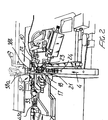
- the sewing machine according to the present invention which has been generally indicated by the reference number 1, comprises two sewing units, respectively a horizontal needle bar sewing unit 2 and a vertical needle bar central sewing unit 3, which are sequentially arranged, or cascade arranged, along the cloth article to be seamed feeding direction 4.
- the sewing units 2 and 3 can comprise two sewing units, respectively of a horizontal needle bar type and a vertical needle bar type, of conventional type, for example of the type comprising a main shaft 5, rotatively driven about its rotary axis, for example by an electric motor which, through a suitable transmission, including, for example, driving belts 6 and 7, drives two driven shafts 8 and 9 which, in turn, by known types of linkage and cam systems, which have been only partially shown in the figures of the accompanying drawings, will drive the horizontal needle bar 10 of the sewing unit 2 and the vertical needle bar 11 of the sewing unit 3.
- a suitable transmission including, for example, driving belts 6 and 7, drives two driven shafts 8 and 9 which, in turn, by known types of linkage and cam systems, which have been only partially shown in the figures of the accompanying drawings, will drive the horizontal needle bar 10 of the sewing unit 2 and the vertical needle bar 11 of the sewing unit 3.
- the two driven shafts 8 and 9 instead of being coupled to a single and same main shaft 5, can also be driven by individual electric motors, suitable synchronized with one another so as to provide a desired timing of the driving of the horizontal needle bar 10 with the vertical needle bar 11, as well as of the several component elements of the two sewing units 2 and 3, so as to progressively cause the cloth article to be seamed to advance along the cloth article feeding direction 4.
- the sewing unit 2 is preferably arranged under a cloth article bearing panel 12, which is substantially horizontally arranged, for the two parts or borders 13a and 13b of the cloth article to be seamed to one another.
- the bearing panel 12 is constituted by covering plates 14 and 15, having any suitable configurations, which are affixed to the bearing framework of the sewing machine.
- the feeding of the cloth article to be seamed along the feeding direction 4 is obtained, in a per se known manner, for example by using feeding grippers, conventionally included in conventional horizontal needle bar sewing units and vertical needle bar sewing units.
- the horizontal needle bar 10 can be provided with either one or more sewing needles 16, which are driven by the driven shaft 8, with a reciprocating translation motion along a substantially horizontal direction and transversal of the feeding direction 4.
- the needle or needles 16 cooperate with one or more crochets, not shown in the drawings, of conventional types, in order to form the seaming stitches.
- the sewing machine comprises moreover, near the working region of the horizontal needle bar 10, a first guide defining, in parallel to the feeding direction 4, a first passage 18 for the two parts or borders 20a and 20b of the cloth portions 13a and 13b to be seamed, which parts are arranged with a mutually facing relationship in a substantially vertical plane.
- the first guide 17 comprises a needle plate 21, defining a bearing surface, which is substantially vertical and parallel to said feeding direction 4, for the two cloth parts or borders 20a and 20b and a foot element 22, facing the bearing plane or surface defined by the needle plate 21.
- the needle plate 21 and the foot element 22 define therebetween a passage 18 for the two cloth parts or borders 20a and 20b.
- the foot element 22 can swing about a vertical axis 23, which is laterally spaced from the needle plate 21, away from the needle plate 18 and against the biassing of a biassing spring 24, so as to fit the different thicknesses of the cloth parts 20a and 20b.
- the needle plate 21 can be formed passage means for the cloth article feeding grippers, as the cloth article is seamed.
- the covering plates 14 and 15, which define the bearing panel 12 for the cloth article to be seamed, also define the inlet of the first guide 17, which inlet substantially comprises two side walls 25a and 25b, which are progressively driven toward one another, according to the feeding direction 4, so as to greatly facilitate the introduction of the cloth parts 20a and 20b, in a substantially vertical direction, inside the passage 18.
- the sewing machine according to the present invention comprises moreover a second guide 30, which is arranged in the machine region between the horizontal needle bar 10 and the vertical needle bar 11, along the feeding direction 4.
- the second guide 30 defines a second passage 31 for the two cloth parts 20a and 20b, seamed to one another by the sewing unit 2, and said second guide is provided with bending means 32 for bending the two cloth parts 20a and 20b in a cross direction with respect to the mentioned feeding direction 4.
- the following sewing unit 3 can perform a felling seaming operation of the two cloth parts 20a and 20b under either one or the other of the cloth portions 13a and 13b, depending on a rightwardly or leftwardly felling operation to be performed.
- the second guide 30 comprises a supporting arm element 33, which is connected to the sewing machine supporting framework and which slidably supports, along a direction substantially perpendicular to the feeding direction 4, a plate-like element 35, in which is defined a guide groove 36 for the two cloth parts 20a and 20b.
- a cut-out 37 which extends at the bottom the guide groove or channel 36.
- top small plates 38a and 38b which are mutually facing along the feeding direction 4 and which define therebetween the second passage 31.
- the top small plates 38a and 38b are connected to further small plates 39a and 39b which can slide either toward one another or away from one another, i.e. transversely of the feeding direction 4, in a sliding seat defined by a portion 40 of the supporting arm element 33 and by further bottom small plates 41a and 41b which are connected to the portion 40.
- the plate-like element 35 in which is defined said guide channel or groove 36, can be driven, transversely of the feeding direction 4, by a pneumatic cylinder 43, which has a cylinder body pivoted to the sewing machine framework and the stem rod 43a of the piston of which operates on the plate-like element 35, as is shown in a more clearly manner in figures 7 and 8.
- the small plates 38a and 38b are provided, on the end portions thereof facing the sewing unit 2, with lead-in bent portions 44a and 44b for the cloth parts 20a and 20b.
- the sewing unit 2 is preferably mounted on a slide, which can be controllably driven, for example by a pneumatic cylinder provided with limit elements, or by a nut-nutscrew assembly, in a direction transversal of the feeding direction 4, with respect the sewing unit 2.
- the subject sewing machine comprises moreover pneumatic means for allowing the cloth portions 13a and 13b to be held properly spread apart on the bearing panel 12, said portions 13a and 13b extending from the two cloth parts 20a and 20b being seamed during the felling seaming operation.
- the above mentioned pneumatic means comprise pressurized air jet delivery nozzle 50 which are supported, immediately upstream of the working region of the vertical needle bar 11, and which are faced to the top of the bearing panel 12, so as to cause the cloth portions 13a and 13b to be held spread apart on said bearing panel 12, during the seaming operation.
- entraining means Downstream of the vertical needle bar 11, according to the feeding direction 14, are provided entraining means for entraining or driving the seamed cloth article, said entraining or driving means being indicated by the reference number 60.
- the mentioned driving means in particular, comprise a driving belt 61 entrained about a driving pulley 62 and two transmission pulleys 63 and 64, as well as a further tension pulley 65, according to a closed loop, extending, at least for a portion thereof, near the bearing panel 12, so as to engage by the top face thereof with the cloth article, upon seaming thereof, in order to cooperate with said grippers for causing said cloth article to be fed along the feeding direction 4.
- the two cloth parts or borders 20a and 20b of the cloth portions 13a and 13b to be seamed are introduced by the operator, in a mutually facing relationship in a substantially vertical plane, into the first passage 18 defined by the first guide 17.
- the thus engaged cloth parts 20a and 20b are driven along the feeding direction 4 and are subjected to the first seamed operation, performed by the horizontal needle bar 10.
- the thus seamed cloth parts 20a and 20b will enter the second passage 31 of the second guide 30, the end portions of the two cloth parts 20a and 20b being arranged in the guide channel 36.
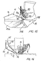
- a corresponding displacement or driving movement is also applied to the seaming or sewing unit 3 which will perform, by means of the vertical needle bar 11, a felling seaming operation 70, as is clearly shown in figure 12.
- the plate-like element 35 will be driven, by the mentioned driving pneumatic cylinder 43, in an opposite direction, so as to cause the cloth parts 20a and 20b to be bent under the cloth portion 13a to be affixed to this portion by the seam performed by the sewing unit 3, which will be displaced or driven transversely of the cloth article feeding direction 4 in the same direction as the driving direction applied to the plate-like element 35 in order to perform the felling seam 71, as clearly shown in figure 14.
- a sewing machine which is specifically designed for performing either a rightwardly or leftwardly felling seaming operation, without requiring any replacing operations on parts of the sewing machine and, accordingly, without interrupting the operation of the sewing machine.
Landscapes
- Engineering & Computer Science (AREA)
- Textile Engineering (AREA)
- Sewing Machines And Sewing (AREA)
Abstract
Description
- The present invention relates to an improved industrial-use sewing machine adapted to perform two sequential seams, and to vary either leftwardly or rightwardly the stitch felling direction.
- As is known, one of the types of seams frequently used in the cloth making industry is the so-called "fell seam".
- This seaming operation usually consists of coupling to one another by a first seam, two parts of a cloth article to be seamed, and then bending the thus seamed parts, under either one or the other of the two portions of the cloth article extending from the two seamed parts of borders.
- Then, by a second seaming operation, the thus bent parts or borders are affixed to the overlaying portion of the cloth article.
- Prior industrial sewing machines for performing the above mentioned operations, conventionally operate in two subsequent operating steps, i.e. by using two different sewing machines, or by using a single sewing machine which, however, requires that several parts of the machine be replaced, depending on a leftwardly or rightwardly felling operation to be performed, or depending on the seamed cloth article parts seamed by the first seaming operation be bent under either one or the other of the two portions of the cloth article seamed at the two mentioned parts of borders.
- These replacing operations, as it should be apparent, will require to use skilled operators and, moreover, they will interrupt the operation of the sewing machine, thereby greatly increasing the cloth article making cost.
- Accordingly, the aim of the present invention is to overcome the above mentioned drawback, by providing an improved industrial use sewing machine which is specifically designed for performing two immediately sequential seams, with the additional capability of changing the felling direction, either rightwardly or leftwardly, without requiring any replacing or fitting operations.
- Within the scope of the above mentioned aim, a main object of the present invention is to provide such a sewing machine which, since it does not require any fitting operations for performing felling seaming operation, independently from the direction of the latter, provides a very high production yield, while reducing to a minimum the operation cost.
- Another object of the present invention is to provide such a sewing machine which is very safe and reliable in operation.
- Yet another object of the present invention is to provide such a sewing machine providing very accurate sequential seams, independently from the felling operation direction.
- According to one aspect of the present invention, the above mentioned aim and objects, as well as yet other objects, which will become more apparent hereinafter, are achieved by an improved industrial-use sewing machine adapted to perform two sequential seams, and to vary either leftwardly or rightwardly the stitch felling direction, characterized in that said sewing machine comprises two sewing units, respectively a horizontal needle bar sewing unit and a vertical needle bar sewing unit, sequentially arranged along a cloth article feeding direction, along said cloth article feeding direction being moreover provided, under a cloth article bearing panel, a first guide defining a first passage for the two parts or borders of the cloth article to be seamed, which parts can be mutually arranged in a facing relationship on a substantially vertical plane, near the horizontal needle bar, and a second guide, arranged between said horizontal needle bar sewing unit and said vertical needle bar sewing unit, said second guide defining a second passage for the two parts of said cloth article, seamed by said horizontal needle bar sewing unit, and being provided moreover with means for bending said two seamed cloth article parts, in a direction transversal of said feeding direction so as to bring said seamed cloth article parts under either one or the other of the two cloth article portions extending from said cloth article parts and arranged above said second guide in a substantially horizontal plane on opposite sides of said second passage, for fell seaming said two cloth article parts, under either one or the other said two article portions as performed by said vertical needle bar sewing unit.
- Further characteristics and advantages of the sewing machine according to the present invention will become more apparent hereinafter from the following detailed disclosure of a preferred, though not exclusive, embodiment, of said sewing machine which is illustrated, by way of an indicative, but not limitative, example, in the accompanying drawings, where:
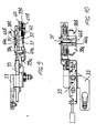
- Figure 1 is a front perspective view illustrating the sewing machine according to the present invention, the coating plates defining the bearing panel for the cloth article to be seamed being omitted;
- Figure 2 illustrates an enlarged portion of the sewing machine shown in figure 1;
- Figure 3 is a schematic elevation view illustrating the sewing machine according to the present invention;
- Figure 4 is a schematic front elevation view illustrating the sewing machine according to the present invention;
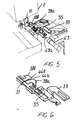
- Figure 5 is a side perspective view illustrating a portion of the sewing machine according to the present invention, related to a second guide thereof;
- Figure 6 is a further perspective view illustrating the second guide;
- Figures 7 and 8 are top plan views respectively illustrating the second guide with the bending means in two different positions;
- Figure 9 is a front elevation view illustrating the second guide;
- Figure 10 is a top plan view illustrating the second guide;
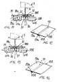
- Figure 11 is a cross-sectional view of figure 7, substantially taken along the section line XI-XI;
- Figure 12 illustrates a felling seam which can be made by properly arranging the bending means shown in figure 11;
- Figure 13 is a cross-sectional view of figure 8, substantially taken along the section line XIII-XIII;
- Figure 14 illustrates the felling or fell seam performed by properly arranging the bending means as shown in figure 13;
- Figure 15 is a front perspective view illustrating that portion of the subject sewing machine arranged immediately upstream of the vertical needle bar sewing unit; and
- Figure 16 is a side elevation view illustrating a detail of the sewing machine according to the present invention.
- With reference to the number references of the above mentioned figures, the sewing machine according to the present invention, which has been generally indicated by the
reference number 1, comprises two sewing units, respectively a horizontal needlebar sewing unit 2 and a vertical needle barcentral sewing unit 3, which are sequentially arranged, or cascade arranged, along the cloth article to be seamedfeeding direction 4. - More specifically, the
sewing units main shaft 5, rotatively driven about its rotary axis, for example by an electric motor which, through a suitable transmission, including, for example,driving belts shafts horizontal needle bar 10 of thesewing unit 2 and thevertical needle bar 11 of thesewing unit 3. - In this connection it should be apparent that the two driven
shafts main shaft 5, can also be driven by individual electric motors, suitable synchronized with one another so as to provide a desired timing of the driving of thehorizontal needle bar 10 with thevertical needle bar 11, as well as of the several component elements of the twosewing units article feeding direction 4. - The
sewing unit 2, as shown, is preferably arranged under a clotharticle bearing panel 12, which is substantially horizontally arranged, for the two parts orborders - More specifically, the
bearing panel 12 is constituted by coveringplates - In particular, the feeding of the cloth article to be seamed along the
feeding direction 4 is obtained, in a per se known manner, for example by using feeding grippers, conventionally included in conventional horizontal needle bar sewing units and vertical needle bar sewing units. - The
horizontal needle bar 10 can be provided with either one ormore sewing needles 16, which are driven by the drivenshaft 8, with a reciprocating translation motion along a substantially horizontal direction and transversal of thefeeding direction 4. - The needle or
needles 16 cooperate with one or more crochets, not shown in the drawings, of conventional types, in order to form the seaming stitches. - The sewing machine according to the present invention comprises moreover, near the working region of the
horizontal needle bar 10, a first guide defining, in parallel to thefeeding direction 4, afirst passage 18 for the two parts or borders 20a and 20b of thecloth portions - More particularly, the
first guide 17 comprises aneedle plate 21, defining a bearing surface, which is substantially vertical and parallel to saidfeeding direction 4, for the two cloth parts or borders 20a and 20b and a foot element 22, facing the bearing plane or surface defined by theneedle plate 21. - The
needle plate 21 and the foot element 22 define therebetween apassage 18 for the two cloth parts or borders 20a and 20b. - As shown, the foot element 22 can swing about a
vertical axis 23, which is laterally spaced from theneedle plate 21, away from theneedle plate 18 and against the biassing of a biassingspring 24, so as to fit the different thicknesses of the cloth parts 20a and 20b. - In the
needle plate 21, moreover, can be formed passage means for the cloth article feeding grippers, as the cloth article is seamed. - The
covering plates bearing panel 12 for the cloth article to be seamed, also define the inlet of thefirst guide 17, which inlet substantially comprises twoside walls 25a and 25b, which are progressively driven toward one another, according to thefeeding direction 4, so as to greatly facilitate the introduction of the cloth parts 20a and 20b, in a substantially vertical direction, inside thepassage 18. - The sewing machine according to the present invention comprises moreover a
second guide 30, which is arranged in the machine region between thehorizontal needle bar 10 and thevertical needle bar 11, along thefeeding direction 4. - The
second guide 30 defines asecond passage 31 for the two cloth parts 20a and 20b, seamed to one another by thesewing unit 2, and said second guide is provided withbending means 32 for bending the two cloth parts 20a and 20b in a cross direction with respect to the mentionedfeeding direction 4. - Thus, it will be possible to bring the two seamed cloth parts under either one or the other of the two
cloth portions second guide 30 in a substantially horizontal plane and being arranged on opposite sides with respect to thepassage 31. - Thus, the following
sewing unit 3 can perform a felling seaming operation of the two cloth parts 20a and 20b under either one or the other of thecloth portions - More specifically, the
second guide 30 comprises a supportingarm element 33, which is connected to the sewing machine supporting framework and which slidably supports, along a direction substantially perpendicular to thefeeding direction 4, a plate-like element 35, in which is defined aguide groove 36 for the two cloth parts 20a and 20b. - Under the guide groove or
channel 36, in the supportingarm element 33 is defined a cut-out 37 which extends at the bottom the guide groove orchannel 36. - On the top of the guide groove or
channel 36, are arranged two topsmall plates feeding direction 4 and which define therebetween thesecond passage 31. - The top
small plates small plates 39a and 39b which can slide either toward one another or away from one another, i.e. transversely of thefeeding direction 4, in a sliding seat defined by aportion 40 of the supportingarm element 33 and by further bottomsmall plates 41a and 41b which are connected to theportion 40. - In particular, the sliding movement of the
small plates 39a and 39b away from one another is counter-biassed byreturn springs 42. - Thus, by causing the
small plates 39a and 39b and, accordingly, thesmall plates - The plate-
like element 35, in which is defined said guide channel orgroove 36, can be driven, transversely of thefeeding direction 4, by apneumatic cylinder 43, which has a cylinder body pivoted to the sewing machine framework and thestem rod 43a of the piston of which operates on the plate-like element 35, as is shown in a more clearly manner in figures 7 and 8. - The
small plates sewing unit 2, with lead-inbent portions - The
sewing unit 2 is preferably mounted on a slide, which can be controllably driven, for example by a pneumatic cylinder provided with limit elements, or by a nut-nutscrew assembly, in a direction transversal of thefeeding direction 4, with respect thesewing unit 2. - The subject sewing machine comprises moreover pneumatic means for allowing the
cloth portions bearing panel 12, saidportions - As shown, the above mentioned pneumatic means comprise pressurized air
jet delivery nozzle 50 which are supported, immediately upstream of the working region of thevertical needle bar 11, and which are faced to the top of thebearing panel 12, so as to cause thecloth portions panel 12, during the seaming operation. - Downstream of the
vertical needle bar 11, according to thefeeding direction 14, are provided entraining means for entraining or driving the seamed cloth article, said entraining or driving means being indicated by thereference number 60. - The mentioned driving means, in particular, comprise a
driving belt 61 entrained about adriving pulley 62 and twotransmission pulleys bearing panel 12, so as to engage by the top face thereof with the cloth article, upon seaming thereof, in order to cooperate with said grippers for causing said cloth article to be fed along thefeeding direction 4. - The operation of the sewing machine according to the present invention, and as above disclosed, is the following.
- The two cloth parts or borders 20a and 20b of the
cloth portions first passage 18 defined by thefirst guide 17. - The thus engaged cloth parts 20a and 20b are driven along the
feeding direction 4 and are subjected to the first seamed operation, performed by thehorizontal needle bar 10. - At the outlet of the
first passage 18, the thus seamed cloth parts 20a and 20b will enter thesecond passage 31 of thesecond guide 30, the end portions of the two cloth parts 20a and 20b being arranged in theguide channel 36. - If a rightwardly felling operation is required, then the plate-
like element 35 will be driven, by the drivingpneumatic cylinder 43, rightwardly, as is clearly shown in figure 11. - Thus, the two cloth parts or borders 20a and 20b will be bent under the
cloth portion 13b to be seamed. - A corresponding displacement or driving movement is also applied to the seaming or
sewing unit 3 which will perform, by means of thevertical needle bar 11, a felling seamingoperation 70, as is clearly shown in figure 12. - As, on the contrary, a leftwardly felling operation is required, then the plate-
like element 35 will be driven, by the mentioned drivingpneumatic cylinder 43, in an opposite direction, so as to cause the cloth parts 20a and 20b to be bent under thecloth portion 13a to be affixed to this portion by the seam performed by thesewing unit 3, which will be displaced or driven transversely of the clotharticle feeding direction 4 in the same direction as the driving direction applied to the plate-like element 35 in order to perform the felling seam 71, as clearly shown in figure 14. - From the above disclosure and from an observation of the figures of the accompanying drawings, it should be apparent that the sewing machine according to the present invention fully achieves the intended aim and objects.
- In particular, the fact is to be pointed out that a sewing machine has been provided which is specifically designed for performing either a rightwardly or leftwardly felling seaming operation, without requiring any replacing operations on parts of the sewing machine and, accordingly, without interrupting the operation of the sewing machine.
- While the sewing machine according to the present invention has been disclosed and illustrated with reference to preferred embodiments thereof, it should be apparent that the disclosed embodiments are susceptible to several modifications and variations, all of which will come within the scope of the appended claims.
Claims (14)
- An improved industrial-use sewing machine adapted to perform two sequential seams, and to vary either leftwardly or rightwardly the stitch felling direction, characterized in that said sewing machine comprises two sewing units, respectively a horizontal needle bar sewing unit and a vertical needle bar sewing unit, sequentially arranged along a cloth article feeding direction, along said cloth article feeding direction being moreover provided, under a cloth article bearing panel, a first guide defining a first passage for the two parts or borders of the cloth article to be seamed, which parts can be mutually arranged in a facing relationship on a substantially vertical plane, near the horizontal needle bar, and a second guide, arranged between said horizontal needle bar sewing unit and said vertical needle bar sewing unit, said second guide defining a second passage for the two parts of said cloth article, seamed by said horizontal needle bar sewing unit, and being provided moreover with means for bending said two seamed cloth article parts, in a direction transversal of said feeding direction so as to bring said seamed cloth article parts under either one or the other of the two cloth article portions extending from said cloth article parts and arranged above said second guide in a substantially horizontal plane on opposite sides of said second passage, for fell seaming said two cloth article parts, under either one or the other said two article portions as performed by said vertical needle bar sewing unit.
- A sewing machine, according to Claim 1, characterized in that said vertical needle bar sewing unit can be controllably driven transversely of said cloth article feeding direction with respect to said horizontal needle bar sewing unit.
- A sewing machine, according to Claims 1 and 2, characterized in that said first guide comprises a needle plate, defining a cloth bearing surface, which is substantially vertical and parallel to said feeding direction, for supporting said two cloth parts to be seamed, as well as a foot element facing the first bearing surface, said needle plate and said foot element defining therebetween the passage for said two cloth parts to be seamed.
- A sewing machine, according to one or more of the preceding claims, characterized in that said foot element can be driven away from said needle plate against the biassing of resilient biassing means for fitting a different thickness of said two cloth parts to be seamed.
- A sewing machine, according to one or more of the preceding claims, characterized in that said first guide is provided with a lead-in portion which is progressively narrowed along said feeding direction.
- A sewing machine, according to one or more of the preceding claims, characterized in that said foot element can swing about a substantially vertical swinging axis laterally spaced from said needle plate, either against said resilient means or by operation of said resilient means.
- A sewing machine, according to one or more of the preceding claims, characterized in that said second guide comprises two top small plates, which are arranged in a mutually facing relationship along said feeding direction and define therebetween said second passage for the two parts of the seamed cloth article; said bending means comprising a plate-like element in which is defined a guide channel arranged under said top small plates, being moreover provided driving means for driving said plate-like element transversely of said feeding direction with respect to said top small plates, for laterally bending, either in a direction or in the other, said two seamed cloth parts.
- A sewing machine, according to one or more of the preceding claims, characterized in that said driving means comprises a driving pneumatic cylinder controllably operating on said plate-like element.
- A sewing machine, according to one or more of the preceding claims, characterized in that said top small plates can be driven away from one another, transversely of said feeding direction, against the biassing of resilient biassing return means.
- A sewing machine, according to one or more of the preceding claims, characterized in that said machine comprises moreover pneumatic means for holding in a spread out relationship on said bearing panel the two portions of said cloth article extending from said two seamed cloth parts, during a felling seaming operation.
- A sewing machine, according to one or more of the preceding claims, characterized in that said pneumatic means comprise pressurized air jet nozzles arranged on the top of said bearing panel and directed toward said bearing panel.
- A sewing machine, according to one or more of the preceding claims, characterized in that said sewing machine comprises moreover, downstream of said vertical needle bar sewing unit, entraining means for entraining said seamed cloth article, which entraining means are arranged according to said feeding direction.
- A sewing machine, according to one or more of the preceding claims, characterized in that said entraining means comprises a driving belt engaging with pulley elements defining a closed loop for said belt, which closed loop extends at least for a portion thereof in a facing relationship with respect to said bearing panel.
- An improved industrial-use sewing machine, adapted to perform two sequential seams, and to vary either leftwardly or rightwardly the stitch felling direction, according to one or more of the preceding claims, and substantially as broadly disclosed and illustrated and for the intended aim and objects.
Applications Claiming Priority (2)
| Application Number | Priority Date | Filing Date | Title |
|---|---|---|---|
| IT96MI000988A IT1283025B1 (en) | 1996-05-16 | 1996-05-16 | SEWING MACHINE PERFECTED FOR INDUSTRIAL USE ABLE TO PERFORM TWO SEAMS IN IMMEDIATE SEQUENCE, WITH THE POSSIBILITY OF VARIATION |
| ITMI960988 | 1996-05-16 |
Publications (3)
| Publication Number | Publication Date |
|---|---|
| EP0807705A2 true EP0807705A2 (en) | 1997-11-19 |
| EP0807705A3 EP0807705A3 (en) | 1998-03-18 |
| EP0807705B1 EP0807705B1 (en) | 2002-08-07 |
Family
ID=11374274
Family Applications (1)
| Application Number | Title | Priority Date | Filing Date |
|---|---|---|---|
| EP97830214A Expired - Lifetime EP0807705B1 (en) | 1996-05-16 | 1997-05-09 | Improved industrial-use sewing machine adapted to perform two sequential seams, and to vary either leftwardly or rightwardly the stitch felling direction |
Country Status (4)
| Country | Link |
|---|---|
| EP (1) | EP0807705B1 (en) |
| JP (1) | JPH1043450A (en) |
| DE (1) | DE69714510D1 (en) |
| IT (1) | IT1283025B1 (en) |
Cited By (2)
| Publication number | Priority date | Publication date | Assignee | Title |
|---|---|---|---|---|
| CN110331525A (en) * | 2019-08-13 | 2019-10-15 | 东莞市友航五金科技有限公司 | A kind of sewing machine falls bone device automatically |
| CN112746399A (en) * | 2019-10-30 | 2021-05-04 | 精机机械厂股份有限公司 | Seam folding device of sewing machine |
Families Citing this family (2)
| Publication number | Priority date | Publication date | Assignee | Title |
|---|---|---|---|---|
| CN107130370B (en) * | 2017-06-08 | 2023-01-20 | 际华橡胶工业有限公司 | Stitching device for sewing counter |
| CN111424386B (en) * | 2020-04-07 | 2021-10-22 | 建德市恒欣家纺有限公司 | Sewing machine for spinning |
Family Cites Families (3)
| Publication number | Priority date | Publication date | Assignee | Title |
|---|---|---|---|---|
| US2176643A (en) * | 1938-01-31 | 1939-10-17 | Man Sew Pinking Attachment Cor | Method of making french seams |
| IT1246756B (en) * | 1990-12-28 | 1994-11-26 | Macpi Pressing Div | SEWING MACHINE, FOR INDUSTRIAL USE, WITH A PERFECT STRUCTURE, SUITABLE TO ALLOW THE SUMULTANEOUS EXECUTION OF SEVERAL SEAMS, OF A DIFFERENTIATED TYPE. |
| IT1256321B (en) * | 1992-11-20 | 1995-11-30 | Rimoldi Srl | METHOD AND MACHINE FOR THE EXECUTION OF SEAMS ON FABRIC LINES, AND SEWING OBTAINED |
-
1996
- 1996-05-16 IT IT96MI000988A patent/IT1283025B1/en active IP Right Grant
-
1997
- 1997-05-09 DE DE69714510T patent/DE69714510D1/en not_active Expired - Lifetime
- 1997-05-09 EP EP97830214A patent/EP0807705B1/en not_active Expired - Lifetime
- 1997-05-15 JP JP9125125A patent/JPH1043450A/en active Pending
Cited By (2)
| Publication number | Priority date | Publication date | Assignee | Title |
|---|---|---|---|---|
| CN110331525A (en) * | 2019-08-13 | 2019-10-15 | 东莞市友航五金科技有限公司 | A kind of sewing machine falls bone device automatically |
| CN112746399A (en) * | 2019-10-30 | 2021-05-04 | 精机机械厂股份有限公司 | Seam folding device of sewing machine |
Also Published As
| Publication number | Publication date |
|---|---|
| EP0807705B1 (en) | 2002-08-07 |
| DE69714510D1 (en) | 2002-09-12 |
| ITMI960988A0 (en) | 1996-05-16 |
| IT1283025B1 (en) | 1998-04-03 |
| EP0807705A3 (en) | 1998-03-18 |
| ITMI960988A1 (en) | 1997-11-16 |
| JPH1043450A (en) | 1998-02-17 |
Similar Documents
| Publication | Publication Date | Title |
|---|---|---|
| US4068603A (en) | Apparatus for feeding material for forming a double tuck on the cut edges thereof | |
| US5588384A (en) | Method and apparatus of folding opposite ends of a piece of tape | |
| US4848252A (en) | Automatic machine for sewing different kinds of articles, especially articles made of leather | |
| JP2017221644A (en) | Covering chain stitch sewing machine | |
| US4572094A (en) | Sewing machine with workpiece differential transport device | |
| US4043283A (en) | Sewing apparatus employing twin needles | |
| EP0807705B1 (en) | Improved industrial-use sewing machine adapted to perform two sequential seams, and to vary either leftwardly or rightwardly the stitch felling direction | |
| JP3950758B2 (en) | Sewing machine with upper thread clamp and cutter | |
| US4462320A (en) | Workholder for an automatic sewing machine | |
| US4173191A (en) | Sewing unit with sectionwise shiftable clamping device | |
| US5931108A (en) | Process and automatic sewing machine for sewing a flap with a rough closing edge and a pocket on a fabric part in one operation | |
| US4459733A (en) | Method and devices for assembly of helixes into face structures | |
| US4296696A (en) | Device for producing sewing seam patterns of stitch groups | |
| US4459925A (en) | Cycle sewing machine | |
| CA1068989A (en) | Stitch shortening and tacking assembly | |
| CN101173425A (en) | Buttonhole Sewing Machine | |
| EP0494052B1 (en) | Industrial sewing machine for simultaneously making different seaming patterns | |
| US6105523A (en) | Belt-loop supply apparatus | |
| CN211079553U (en) | Four-wire machine for medical protective clothing | |
| US20220290346A1 (en) | Sewing method and device for same | |
| EP0353208B1 (en) | Industrial sewing machine for simultaneously performing a plurality of improved seaming lines | |
| US2914009A (en) | Fabric trimming and thread laying mechanism for sewing machines | |
| JP3392712B2 (en) | Method and apparatus for making seams in dough material | |
| CN107488942A (en) | Flat seam sewing machine | |
| US4559883A (en) | Sewing machine for forming a plurality of seams |
Legal Events
| Date | Code | Title | Description |
|---|---|---|---|
| PUAI | Public reference made under article 153(3) epc to a published international application that has entered the european phase |
Free format text: ORIGINAL CODE: 0009012 |
|
| AK | Designated contracting states |
Kind code of ref document: A2 Designated state(s): DE ES FR GB |
|
| PUAL | Search report despatched |
Free format text: ORIGINAL CODE: 0009013 |
|
| AK | Designated contracting states |
Kind code of ref document: A3 Designated state(s): DE ES FR GB |
|
| 17P | Request for examination filed |
Effective date: 19980714 |
|
| AKX | Designation fees paid |
Free format text: DE ES FR GB |
|
| RBV | Designated contracting states (corrected) |
Designated state(s): DE ES FR GB |
|
| 17Q | First examination report despatched |
Effective date: 20000921 |
|
| GRAG | Despatch of communication of intention to grant |
Free format text: ORIGINAL CODE: EPIDOS AGRA |
|
| GRAG | Despatch of communication of intention to grant |
Free format text: ORIGINAL CODE: EPIDOS AGRA |
|
| GRAH | Despatch of communication of intention to grant a patent |
Free format text: ORIGINAL CODE: EPIDOS IGRA |
|
| GRAH | Despatch of communication of intention to grant a patent |
Free format text: ORIGINAL CODE: EPIDOS IGRA |
|
| GRAA | (expected) grant |
Free format text: ORIGINAL CODE: 0009210 |
|
| AK | Designated contracting states |
Kind code of ref document: B1 Designated state(s): DE ES FR GB |
|
| PG25 | Lapsed in a contracting state [announced via postgrant information from national office to epo] |
Ref country code: FR Free format text: LAPSE BECAUSE OF NON-PAYMENT OF DUE FEES Effective date: 20020807 |
|
| REG | Reference to a national code |
Ref country code: GB Ref legal event code: FG4D |
|
| REF | Corresponds to: |
Ref document number: 69714510 Country of ref document: DE Date of ref document: 20020912 |
|
| PG25 | Lapsed in a contracting state [announced via postgrant information from national office to epo] |
Ref country code: DE Free format text: LAPSE BECAUSE OF FAILURE TO SUBMIT A TRANSLATION OF THE DESCRIPTION OR TO PAY THE FEE WITHIN THE PRESCRIBED TIME-LIMIT Effective date: 20021108 |
|
| PG25 | Lapsed in a contracting state [announced via postgrant information from national office to epo] |
Ref country code: ES Free format text: LAPSE BECAUSE OF FAILURE TO SUBMIT A TRANSLATION OF THE DESCRIPTION OR TO PAY THE FEE WITHIN THE PRESCRIBED TIME-LIMIT Effective date: 20030228 |
|
| PG25 | Lapsed in a contracting state [announced via postgrant information from national office to epo] |
Ref country code: GB Free format text: LAPSE BECAUSE OF NON-PAYMENT OF DUE FEES Effective date: 20030509 |
|
| PLBE | No opposition filed within time limit |
Free format text: ORIGINAL CODE: 0009261 |
|
| STAA | Information on the status of an ep patent application or granted ep patent |
Free format text: STATUS: NO OPPOSITION FILED WITHIN TIME LIMIT |
|
| 26N | No opposition filed |
Effective date: 20030508 |
|
| GBPC | Gb: european patent ceased through non-payment of renewal fee |
Effective date: 20030509 |