EP0807566B1 - Structure de plancher de chargement d'un véhicule automobile - Google Patents
Structure de plancher de chargement d'un véhicule automobile Download PDFInfo
- Publication number
- EP0807566B1 EP0807566B1 EP97107872A EP97107872A EP0807566B1 EP 0807566 B1 EP0807566 B1 EP 0807566B1 EP 97107872 A EP97107872 A EP 97107872A EP 97107872 A EP97107872 A EP 97107872A EP 0807566 B1 EP0807566 B1 EP 0807566B1
- Authority
- EP
- European Patent Office
- Prior art keywords
- truck
- floor
- floor panel
- floor structure
- longitudinal
- Prior art date
- Legal status (The legal status is an assumption and is not a legal conclusion. Google has not performed a legal analysis and makes no representation as to the accuracy of the status listed.)
- Expired - Lifetime
Links
Images


Classifications
-
- B—PERFORMING OPERATIONS; TRANSPORTING
- B62—LAND VEHICLES FOR TRAVELLING OTHERWISE THAN ON RAILS
- B62D—MOTOR VEHICLES; TRAILERS
- B62D25/00—Superstructure or monocoque structure sub-units; Parts or details thereof not otherwise provided for
- B62D25/20—Floors or bottom sub-units
- B62D25/2054—Load carrying floors for commercial vehicles
-
- B—PERFORMING OPERATIONS; TRANSPORTING
- B62—LAND VEHICLES FOR TRAVELLING OTHERWISE THAN ON RAILS
- B62D—MOTOR VEHICLES; TRAILERS
- B62D29/00—Superstructures, understructures, or sub-units thereof, characterised by the material thereof
- B62D29/04—Superstructures, understructures, or sub-units thereof, characterised by the material thereof predominantly of synthetic material
- B62D29/043—Superstructures
Definitions
- the present invention relates to a floor structure for a truck's load-carrying platform, and more particularly to a floor structure which is applicable to any type of load-carrying platform such as a van's platform (i.e., closed box-type platform), a platform which opens in three directions (e.g., a pick-up truck's platform), a platform equipped with a single gate which opens in a backward direction and a wing-body type platform which has one or more pairs of swing doors adapted to open like bird's wings in a width direction of a truck, and more particular to a floor structure according to the characteristics of the preamble of independent claim 1.
- a van's platform i.e., closed box-type platform
- a platform which opens in three directions e.g., a pick-up truck's platform
- a platform equipped with a single gate which opens in a backward direction
- a wing-body type platform which has one or more pairs of swing doors adapted to open like bird's wings
- a wing body-type platform equipped with a single pair of swing doors or roofs 202 is illustrated as an example of typical truck's load-carrying platforms.
- This platform has relatively large dimensions and fixed on a frame work of a truck.
- the platform has gates 201 along lateral edges of the truck and the wing roofs 202 over the gates.
- At a rear end of the platform provided is a pair of biparting rear doors 203.
- a front end of the platform is closed by a front wall 204.
- a cab (not shown) is situated in front of the front wall 204.
- the gates 201, wing roofs 202, rear doors 203 and front wall 204 are supported from a conventional floor structure 205 of the truck's platform respectively.
- FIG. 20 of the accompanying drawings illustrated is a perspective view of part of the floor structure 205 in an enlarged scale partly in cross section.
- the floor structure 205 is secured on a pair of side frames 206 (only one of them is depicted) of a ladder-like truck frame via spacers 207 by suitable fastening members such as U-bolts (not shown).
- the side frames 206 extend in a longitudinal direction of the truck.
- the floor structure 205 includes longitudinal sills or joists 208 extending along the side rails 206 and secured on the side rails 206, transversal sills 209 extending in a direction perpendicular to the longitudinal sills 208 across the width of the platform and secured on the longitudinal sills 208 and the floor plate 210 placed on the transverse sills 209.
- the floor plate 210 forms a platform floor.
- Each of the longitudinal and transversal sills 208 and 209 is a steel member having a U-shaped cross section.
- the longitudinal and transversal sills 208 and 209 form in combination a frame work to support the floor plate 210 which is situated on the frame work. The rigidity of the floor structure 205 is insured by this frame work.
- the floor plate 210 is generally made of wood.
- the conventional floor structure 205 is made by the longitudinal and transversal sills 208 and 209 assembled like a lattice and the floor plate 210 placed on them. Therefore, the floor structure 205 has a thickness Tz which is relatively large.
- Tz thickness which is relatively large.
- the conventional floor structure 205 is also heavy in weight since it includes the steel frame members 208 and 209 and the woody floor plate 210.
- the floor structure 205 itself must have sufficient rigidity or strength since it helps insure or partly determines the truck's overall bending/flexural rigidity as well as torsional rigidity.
- a typical truck has wheels below the platform floor and outside the side rails of the truck's frame, and the wheels are frequently caused to move up and down due to projections and recesses on and in a road surface and/or cornering (or rolling) movements of the truck. Therefore, if the floor structure of the truck's platform is positioned at a lower height from the ground or road surface, the wheels may collide with the floor panel when the wheels move upward.
- a floor structure according to the first part of claim 1 is known from EP-A-0 061 919.
- EP-A-0 635 418 discloses a floor structure for a load-carrying platform of a truck.
- the floor is formed by two parallel outer layers of glass reinforced plastics spaced apart by an intermediate layer of polyurethane foam and has two straight longitudinal sills which extend on the underside of the floor in parallel transversely spaced positions.
- a similar structure is known from BE-A-679 917.
- An object of the present invention is to provide a floor structure for a vehicle's platform which can eliminate the above-described problems which the prior art structure has.
- the floor plate member under which the wheels of the vehicle are positioned, is reduced in thickness. Specifically the undersurface of the floor plate member is recessed or cut out. Consequently, collision or contact between the vehicle's wheels and the floor plate member is reliably avoided even if the wheels move up and down while the vehicle is running on a road.
- the floor plate member may only be reduced in thickness in areas close to the lateral edges of the floor plate member since collision of the wheels against the floor plate member mostly occurs in these areas only.
- the floor plate member and the longitudinal sills may be simultaneously manufactured as one piece unit or may be separately prepared and jointed later.
- the hollow FRP floor structure encapsulating foam material reduces the weight of the floor structure but exerts high rigidity.
- the transversal sills are dispensed with from this floor structure so that the thickness of the floor structure is also reduced. Accordingly, it is possible to provide a platform having a lower floor.
- the longitudinal sills on which the floor plate member is supported insures sufficient bend-ing/flexural rigidity as well as torsional rigidity of the vehicle.
- Figure 2 illustrates the bottom view of a floor structure 101 of this embodiment
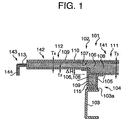
- Figure 1 illustrates the sectional view as taken along the line A-A of Figure 2
- Figure 3 the sectional view as taken along the line B-B.
- the top of the drawing sheet for Figure 2 corresponds to the front of the truck.
- the floor structure 101 is employed in, for example, a wing-body type platform.
- the floor structure 101 includes a floor panel 102 which defines a floor of the platform and a pair of longitudinal sills 104 extending along the side rails 103 of the truck under the floor panel 102.
- the floor panel 102 is a single thin and hollow element made from a glass fiber reinforced plastic (GFRP) 105.
- the floor panel 102 therefore has an enclosed construction.
- the longitudinal sills 4 are also made from GFRP.
- Each of the longitudinal sills 4 has a generally U-shaped cross section.
- the floor structure 101 has a hollow box shape having a GFRP outer shell 107 of generally uniform thickness t2. Accordingly, the floor structure 101 is lightweight and possesses high rigidity.
- the floor structure 101 therefore has a thin wall construction as a whole so that the floor height of the platform from the ground may be lowered.
- the longitudinal sills 104 add to rigidity of the floor panel 102 against bending and twisting (or torsion) in a pitching direction. Consequently, the floor structure 101 can prevent deformation of a truck frame, which deformation would be otherwise caused while the truck is running on a road, and can raise the rigidity of the truck frame.
- the interior of the outer shell 107 is filled with a foam 106 such as urethane foam or resin foam.
- the foam material 106 defines a core 108 of the floor structure 101 to improve compression strength of the floor structure 101.
- the two side rails 103 of the truck are longitudinal members of a ladder-like frame work of the truck and extend the length of the floor structure 101.
- the side rails 103 are spaced from each other in the width direction of the truck.
- a plurality of cross members (not shown) spans the side rails 103. In Figure 1, only the left side rail 103 is depicted.
- the floor structure 101 is secured on the side rails 103 via spacers 103a by suitable fastening elements such as bolts and nuts.
- the floor structure 101 is therefore supported from the side rails 103 upon fixing of the longitudinal sills 104 to the spacers 103a.
- the floor panel 102 and the longitudinal sills 104 are separately prepared and joined later.
- One method of manufacturing the floor panel 102 is to first prepare the foam 106 and then attach the GFRP 105 on the surface of the foam 106 to surround or enclose the foam 106. After that, a pair of foam materials 106, which is the basic material for the longitudinal sills 104, is attached to the under face of the floor panel 102 and the GFRP 105 is attached over the foam materials 106 to form the longitudinal sills 104.
- the floor panel 102 and longitudinal sills 104 are united to a single unit.
- an additional material 110 made from CFRP 109 is attached to the whole upper surface of the floor panel 102 and a similar material 115 made from CFRP 109 is attached to an inner wall of a lower portion of each sill 104.
- CFRP 109 is a material having a high longitudinal elasticity.
- the floor panel 102 extends the length and width of the platform and has a thickness T3 in most part thereof and a thickness T4 in those parts which face truck's wheels.
- positions of the truck's wheels under the platform are designated by C1, C21, C22, C31 and C32.
- the outer portions 112 of the floor panel 102 are made only thinner (thickness T4 in Figure 1) in areas above the axles C1, C21, C22, C31 and C32.
- Other portions of the floor panel 102 have the same thickness T3 ( Figure 1) as the center portion 111 of the floor panel 102.
- the floor panel 102 has the larger thickness T3 between the longitudinal sills 4 (or in a center portion 111 of the floor panel 102) and the smaller,thickness T4 in the outer portions 112 of the floor panel 102.
- the floor panel 102 includes the thicker portion 141 having the thickness T3 and the thinner portions 142 having the thickness T4, but the thicker portion 141 and thinner portions 142 form in combination a planar upper surface of the floor panel 102.
- the lower surface of the thinner portions 142 is higher than the thicker portion 141 by delta H.
- the floor panel 102 is recessed in its lower surface above the truck's wheels.
- the truck's wheels are positioned under the recessed portions of the outer portions 112 of the floor panel 102.
- the floor structure 101 is applicable to various types of truck having different wheel bases. Specifically, if the truck is a four-axle vehicle, then an axle extending transversely below a cab of the truck (not shown) is a front front axle or first front axle which determines the steering of the truck, the axle C1 represents a front rear axle or second front axle which also determines the steering, the axle C22 represents a rear front axle or first rear axle and the axle C32 represents a rear rear axle or second rear axle. If the truck is a three-axle vehicle, then the truck includes the first front axle under the cab (not shown), the first rear axle C21 and the second rear axle C31.
- the four- and three-axle trucks may have rear axles at different positions. Further, the three-axle trucks may have different rear axle positions depending upon specifications of the truck, load balance, weight of the cab and the like to realize an appropriate truck design.
- the floor structure 101 has the following construction.
- the thinner portions 142 are formed in certain areas above the second front axle C1, the first rear axles C21 and C22 and the second rear axles C31 and C32 respectively and each recessed portion 142 has a width equal to that of the associated outer portion 112 of the floor panel 102.
- each outer portion 112 of the floor panel 102 has a support 143 for a gate (not shown) along a lateral edge thereof.
- the gate support 143 has greater rigidity than other portions to bear the weight of the gate.
- the gate support 143 has a generally rectangular cross section along the thicker portions 141 of the floor panel 102 as illustrated in Figure 3 and has a generally inverted L-shaped cross section along the thinner portions 142 as illustrated in Figure 1.
- An inverted L-shaped core material 144 made from for example aluminum is embedded in the gate support 143 extending from the thinner portion 142.
- the gate is pivotably mounted on the associated gate support 143 using hinges or the like such that the gate can stand vertically in an upright position and pivot downwardly clockwise or counterclockwise. In the upright position, the gate stands on a stepwise portion 113 of the gate support 143.
- the floor panel 102 since the floor panel 102 has the thinner portions 142 above the wheels 145 of the truck, the height of the floor panel 102 from the ground is raised at the thinner portions 142 only. Accordingly, the floor structure 101 is generally a low floor structure while maintaining sufficient rigidity. Even if the wheels 145 are forced upward, top portions 146 of the wheels 145 still do not collide with the floor panel 102 since a relatively large clearance is formed between the floor panel 102 and the wheel top 146.
- the length of the thinner portions 142 in the longitudinal direction of the truck for the rear front wheels (C21, C22) and the rear rear wheels (C31, C32) is unnecessarily long such that the illustrated floor structure 101 can be used for any of trucks having various types of wheel base. If the truck has the axles C1, C21 and C31 in addition to the axle under,the cab, which may be referred to as a short wheel base truck, it is not necessary to consider interference or collision between the wheel top portions 146 and the floor panel 102 above the positions of the axles C22 and C32 since the truck does not have the axles C22 and C32. These portions are designated at 147. In other words, the portions 147 are unnecessarily thin and has low rigidity.
- reinforcing ribs 148 are attached to the lower surfaces of the thinner portions 147 after the floor structure 101 is manufactured.
- Each rib 148 extends transversally. Therefore, the thinner portions 147 are raised in rigidity and undesired low rigidity portions are eliminated. A detailed structure about the rib 148 will be described later.
- the thinner portions 142 above the axles C21 and C31 may be able to have the same thickness T3 as the thicker portions 141.
- These portions are designated at 149 in Figure 2. Similar reinforcing ribs 150 are attached to the lower surfaces of the portions 149 in this case.
- the reinforcing ribs 150 may be attached to the lower surfaces of the thinner portions 142 above the second front axle C1.
- the floor structure 101 can be manufactured at lower cost and easily.
- Figure 5 illustrates the bottom view of a floor structure 101 according to a first modification and Figure 6 illustrates the cross section taken along the line C-C of Figure 5.
- the floor panel 102 has a center portion 111 of thickness T3 and outer portions 112 of thickness T4. This floor panel 102 also has the thicker portion 141 and the thinner portions 142. A number of ribs 151 is attached to the lower surface of each outer portion 112. Each rib 151 extends in the width direction of the truck. The ribs 151 are provided at predetermined intervals in the length direction of the. truck. As best illustrated in Figure 5, the outer portions 112 have the thickness T4 across their length and width entirely. In Figure 2, on the contrary, the outer portions 112 have the thickness T4 only in the axle areas and other portions have the larger thickness T3. Therefore, this modification provides a thinner floor panel 102 as a whole than that shown in Figure 2.
- the ribs 152 may be attached to the lower surfaces of the floor panel 102 above the C21, C22, C31 and C32 as desired, like attachment of the ribs 148 and 150.
- FIG. 7a illustrates an example having a rectangular cross section.
- Each rib 151/152 is made from combination of the outer GFRP layer 107 and the inner foam 106.
- the ribs are provided on the lower surface of the outer portions 112 of the floor panel 102 in the same manner as utilized for provision of the longitudinal sills 104 onto the floor panel 102.
- the outer layer 107 may be made from CFRP 109.
- the outer layer 107 may be formed from combination of GFRP layer 105 and CFRP layer 109.
- Figure 7b illustrates an example of T-shaped one
- Figure 7c illustrates an example of I-shaped one
- Figure 7d illustrates an inverted L-shaped one.
- the ribs 151/152 are made from GFRP 105 and attached to the lower surface of the floor panel 102. It should be noted here that the material 105 may be replaced with CFRP 109 or the rib may be formed from combination of GFRP layer 105 and CFRP layer 109. It is of course that other particular shapes and materials may be equally employed for the ribs 151/152.
- the ribs 151 and 152 connect the associated longitudinal sill 104 with the associated gate support 143 and bear a vertical load applied to the gate support 143 from the mounted gate and related parts.
- the ribs 151 and 152 significantly raise flexural rigidity of the outer portions 112 of the floor panel 102.
- ribs 148 and 150 are similar to the ribs 151 and 152.
- Ribs designated at 151a may be used as the ribs 151 and brackets for mounting of accessory parts such as side bumpers, splash boards and mudguards.
- Figure 8 illustrates a bottom view of a floor structure 101 according to a second modification
- Figure 9 illustrates a cross sectional view taken along the line E-E.
- the floor structure 101 includes a floor panel 102 having a center portion 111 and outer portions 112.
- the thickness of the center portion 111 is T3 entirely and the thickness of the outer portions 112 is mostly T3.
- part 142 of the outer portions 112 has a smaller thickness T4.
- a majority of the floor panel 102 is made from a thicker panel portion 141, and the remainder of the floor panel is made from the thinner panel portions 142.
- the thinner panel portions 142 are provided at positions corresponding to a second set of front wheels (axle C1), a first set of rear wheels (axle C21/C22) and a second set of rear wheels (axle C31/C33) as illustrated in Figure 8.
- the thinner portion 142 do not extend the width of the associated outer portion 112 from the lateral edge of the floor panel 102: it rather terminates before reaching the longitudinal sill 104.
- the width of the thinner portions 142 of this modification is smaller than that of the thinner portions 142 shown in Figures 2 and 5 (i.e., reduced to approximately half).
- the width of the thinner or recessed portions 142 is determined to be sufficiently large such that the truck's wheels (not shown) do not collide with the lower surface of the floor panel 102. Referring back to Figure 4, specifically, the collision between the wheel top portions 146 and the overextending recessed portion 142 only occurs under about an outer quarter of the recessed portion 142.
- the floor panel 102 is only reduced in thickness in such an area. Since other part of the floor panel 102 is made from the thicker portion 141, the rigidity of the floor panel 102 is improved. As depicted in Figure 8, the thinner portions 142 above the second front wheels supported on the axle C1 are wider than those above the first and second rear wheels supported on the axles C21 to C33 since the second front wheels are caused to turn right and left upon a steering operation by a driver of the truck and the interference between the floor panel 102 and the second front wheels should be avoided during such a steering operation.
- ribs 153 On the under surface of the outer portions 112 of the floor panel 102, provided is a number of ribs 153 for mounting of accessory parts such as side bumpers.
- the ribs 153 are attached to the thicker portion 141 having relatively high rigidity so that the number of the ribs 153 can be reduced to as small as possible, as far as the ribs 153 can support the side bumpers safely thereon.
- the above described ribs 148, 150 and 152 may be provided on the thinner portions 142.
- a vertically extending sharp connection 154 is formed between the thinner portion 142 and the thicker portion 141 in this modification.
- the thinner and thicker portions 142 and 141 may be connected by a gentle transition 155 as illustrated in Figure 10.
- the manufacturing of the floor panel 102 is easier in Figure 10 than in Figure 9.
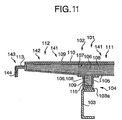
- the outer portions 112 of the floor panel 102 may be reduced in thickness gradually linearly toward the lateral edges of the floor panel to form the thinner portion 142 as illustrated in Figure 11.
- Figures 12 to 18 correspond to Figures 1, 3, 6, 7 and 9 to 11 respectively.
- the floor panel portion 102 and the longitudinal sill portions 104 are made simultaneously as a one piece element whereas in Figures 1, 3, 6, 7 and 9 to 11, these portions are separately manufactured and jointed later.
- the foam 106 is first prepared to have a shape of combined floor panel portion 102 and longitudinal sill portions 104.
- the GFRP 105 is applied over the whole outer surface of the foam 106 such that the floor panel portion 102 and longitudinal sill portions 104 are enclosed by a single outer shell 107 made from the GFRP 105.
- the floor panel portion 102 and longitudinal sill portions 104 also share a mutual core 108 made from the foam 106.
- the laminated layer 110 made from the CFRP 109 covers not only the upper surface of the floor panel portion 102 but also the gate supports 143 and the lower surface of the outer portions 112 of the floor panel portions 102, thereby defining additional layers 156 and 157 continuously.
- the lower surface of the center portion 111 of the floor panel portion 111 is also covered with a layer 158 made from the CFRP 109.
- the rigidity of the floor structure 101 is further improved.
Landscapes
- Engineering & Computer Science (AREA)
- Chemical & Material Sciences (AREA)
- Combustion & Propulsion (AREA)
- Transportation (AREA)
- Mechanical Engineering (AREA)
- Architecture (AREA)
- Structural Engineering (AREA)
- Body Structure For Vehicles (AREA)
Claims (11)
- Structure de plancher (101) pour une plate-forme de support de charge d'un camion, le camion comportant une paire de longerons parallèles (103) s'étendant dans une direction longitudinale du camion et comportant une pluralité de roues (145), la structure de plancher (101) comportant une partie de panneau de plancher (102) constituée d'une matière plastique renforcée par des fibres (105) et encapsulant un matériau de mousse, la partie de panneau de plancher comportant une paroi supérieure, une paroi inférieure et des parties de bord latérales reliant les parois supérieure et inférieure l'une à l'autre, une épaisseur de la partie de panneau de plancher (102) étant définie par une distance entre les parois supérieure et inférieure, et une paire de poutrelles longitudinales (104) s'étendant le long de la paire de longerons (103) sous la partie de panneau de plancher (102), chaque poutrelle longitudinale étant réalisée à partir de matière plastique renforcée par des fibres (105) et encapsulant un matériau de mousse, caractérisée en ce que l'épaisseur de la partie de panneau de plancher (102) est réduite en une pluralité de premières zones (142, 147, 149) au-dessus de la pluralité de roues (145) et est également réduite en une pluralité de secondes zones (149, 147) à proximité des premières zones (147, 149) dans la direction longitudinale du camion, des premières nervures (148, 150) étant fixées à la paroi inférieure de la partie de panneau de plancher (102) dans les secondes zones (149, 147), chacune des premières nervures s'étendant dans la direction de la largeur du camion.
- Structure de plancher selon la revendication 1, caractérisée en ce que la partie de panneau de plancher (102) est réduite en épaisseur dans sensiblement la totalité des zones (112) à l'extérieur des poutrelles longitudinales (104) et une pluralité de secondes nervures (151, 151a) est fixée à la paroi inférieure de la partie de panneau de plancher dans des zones réduites en épaisseur (142), les secondes nervures étant espacées dans la direction longitudinale du camion et chaque seconde nervure s'étendant dans la direction de la largeur du camion.
- Structure de plancher selon la revendication 1, caractérisée en ce que la partie de panneau de plancher (102) est réduite en épaisseur dans des zones prédéterminées (157) proches des parties latérales.
- Structure de plancher selon l'une quelconque des revendications 1 à 3, caractérisée en ce qu'un premier matériau à couches stratifiées (110) est placé sur la paroi supérieure de la partie de panneau de plancher (102).
- Structure de plancher selon l'une quelconque des revendications 1 à 4, caractérisée en ce qu'un second matériau stratifié (115) est fixé à une surface extérieure et/ou intérieure de chaque poutrelle longitudinale.
- Structure de plancher selon la revendication 5, caractérisée en ce que chaque poutrelle longitudinale (104) présente une section transversale en forme de U et est définie par des première à troisième parois s'étendant dans la direction longitudinale du camion respectivement, la première paroi étant dirigée horizontalement vers l'extérieur dans le sens de la largeur du camion, la seconde paroi étant dirigée horizontalement vers l'intérieur dans le sens de la largeur du camion, et la troisième paroi étant dirigée verticalement vers le bas et reliant les première et seconde parois l'une à l'autre au niveau de leurs extrémités inférieures afin de définir la section transversale en forme de U, et le second matériau à couches stratifiées (115) est fixé à une surface extérieure et/ou intérieure de la troisième paroi de chaque poutrelle longitudinale (104).
- Structure de plancher selon la revendication 5 ou 6, caractérisée en ce que le second matériau à couches stratifiées (115) est également fixé à la seconde paroi de chaque poutrelle longitudinale.
- Structure de plancher selon l'une quelconque des revendications 1 à 7, caractérisée en ce qu'un troisième matériau à couches stratifiées (158) est fixé sur la paroi inférieure de la partie de panneau de plancher (102) entre les poutrelles longitudinales (104).
- Structure de plancher selon l'une quelconque des revendications 4 à 8, caractérisée en ce que chacun des premier à troisième matériaux à couches stratifiées (115, 158) est réalisé à partir d'une matière plastique renforcée par des fibres de carbone (109).
- Structure de plancher selon l'une quelconque des revendications 1 à 9, caractérisée en ce que chacune des poutrelles longitudinales (4 ; 104) est réalisée à partir de matière plastique renforcée par des fibres de carbone (109).
- Structure de plancher selon la revendication 10, caractérisée en ce que la paroi inférieure de la partie de panneau de plancher (102) entre les poutrelles longitudinales (104) est réalisée à partir d'une matière plastique renforcée par des fibres de carbone et est dans le prolongement des poutrelles longitudinales (104).
Applications Claiming Priority (6)
| Application Number | Priority Date | Filing Date | Title |
|---|---|---|---|
| JP119162/96 | 1996-05-14 | ||
| JP11916296A JPH09301225A (ja) | 1996-05-14 | 1996-05-14 | トラック用荷台の床板材 |
| JP11916296 | 1996-05-14 | ||
| JP24221496A JPH1086857A (ja) | 1996-09-12 | 1996-09-12 | トラック用荷台の床板材 |
| JP242214/96 | 1996-09-12 | ||
| JP24221496 | 1996-09-12 |
Publications (3)
| Publication Number | Publication Date |
|---|---|
| EP0807566A2 EP0807566A2 (fr) | 1997-11-19 |
| EP0807566A3 EP0807566A3 (fr) | 1998-05-20 |
| EP0807566B1 true EP0807566B1 (fr) | 2003-04-09 |
Family
ID=26456949
Family Applications (1)
| Application Number | Title | Priority Date | Filing Date |
|---|---|---|---|
| EP97107872A Expired - Lifetime EP0807566B1 (fr) | 1996-05-14 | 1997-05-14 | Structure de plancher de chargement d'un véhicule automobile |
Country Status (3)
| Country | Link |
|---|---|
| US (1) | US6092862A (fr) |
| EP (1) | EP0807566B1 (fr) |
| DE (1) | DE69720585T2 (fr) |
Families Citing this family (25)
| Publication number | Priority date | Publication date | Assignee | Title |
|---|---|---|---|---|
| US6109684A (en) * | 1998-03-16 | 2000-08-29 | Reitnouer; Miles A. | Unitized flatbed trailer structure and container truck floor structure |
| US6189930B1 (en) * | 1999-08-03 | 2001-02-20 | Dana Corporation | Joint between side rail and cross member in a vehicle frame assembly |
| FR2802501B1 (fr) * | 1999-12-16 | 2002-03-01 | Auzou Constructeur Polyester | Structure de chargement a plateau composite pour vehicule utilitaire |
| US6296298B1 (en) | 2000-03-14 | 2001-10-02 | L&L Products, Inc. | Structural reinforcement member for wheel well |
| US7041355B2 (en) * | 2001-11-29 | 2006-05-09 | Dow Global Technologies Inc. | Structural reinforcement parts for automotive assembly |
| CN100467243C (zh) * | 2002-01-22 | 2009-03-11 | 陶氏环球技术公司 | 加固的结构主体及其制造方法 |
| BR0309088A (pt) * | 2002-04-15 | 2005-02-09 | Dow Global Technologies Inc | Membros estruturais veiculares melhorados e método para manufaturar tais membros |
| FR2841865B1 (fr) * | 2002-07-03 | 2005-10-28 | Delcroix | Paroi inferieure de caisse destinee a equiper un vehicule de transport, caisse et vehicule de transport equipes de la dite caisse |
| CA2501869C (fr) * | 2002-10-11 | 2010-08-17 | Robert B. Douglas | Structure modulaire permettant de construire des panneaux et leurs procedes de production et d'utilisation |
| WO2004060984A1 (fr) * | 2002-12-27 | 2004-07-22 | Dow Global Technologies Inc. | Colle epoxyde activee par la chaleur et son utilisation dans un insert en mousse structuree |
| JP2004210178A (ja) * | 2003-01-07 | 2004-07-29 | Honda Motor Co Ltd | 車体フレーム |
| JP4938445B2 (ja) * | 2003-03-05 | 2012-05-23 | ダウ グローバル テクノロジーズ エルエルシー | 構造用強化物品及びその製造方法 |
| DE102004034033A1 (de) * | 2004-07-16 | 2006-02-09 | Lüdke, Peter | Reisemobil/Motorhome |
| US7390052B2 (en) * | 2005-07-11 | 2008-06-24 | Fleetwood Enterprises, Inc. | Light weight chassis and hull |
| JP4625528B2 (ja) * | 2009-02-27 | 2011-02-02 | 株式会社シーデーエスニュースチールホームズインターナショナル | 建物の単位構造部材と該単位構造部材を用いた床構造 |
| JPWO2012105717A1 (ja) | 2011-02-03 | 2014-07-03 | 帝人株式会社 | 車両骨格部材 |
| WO2013028630A2 (fr) * | 2011-08-19 | 2013-02-28 | Leroy Hagenbuch | Conception améliorée d'un plancher de benne de camion de chantier |
| DE102013209095A1 (de) * | 2013-05-16 | 2014-11-20 | Bayerische Motoren Werke Aktiengesellschaft | Crashstruktur für ein Fahrzeug |
| SE537683C2 (sv) * | 2013-05-30 | 2015-09-29 | Ssab Technology Ab | Sandwichelement och lastgolv utformat som ett sådant |
| US9114730B1 (en) * | 2014-02-19 | 2015-08-25 | International Truck Intellectual Property Company, Llc | Seat mounting structure in vehicle floor frame |
| DE102016204731A1 (de) * | 2015-04-22 | 2016-10-27 | Bayerische Motoren Werke Aktiengesellschaft | Kraftfahrzeug |
| US10150519B2 (en) | 2016-07-01 | 2018-12-11 | Toyota Motor Engineering & Manufacturing North America, Inc. | Apparatus and method for designing deck sill and rear post |
| DE102018200999A1 (de) * | 2018-01-23 | 2019-07-25 | Volkswagen Ag | Bodenelement für ein Kraftfahrzeug |
| US10343727B1 (en) | 2018-01-31 | 2019-07-09 | Toyota Motor Engineering & Manufacturing North America, Inc. | Two-piece deck post |
| US11235637B1 (en) | 2018-06-28 | 2022-02-01 | Grand Design RV, LLC | Recreational vehicle with underbody insulation |
Family Cites Families (13)
| Publication number | Priority date | Publication date | Assignee | Title |
|---|---|---|---|---|
| FR679917A (fr) * | 1929-08-05 | 1930-04-23 | Cie Generale Des Machines Parl | Perfectionnements aux machines parlantes |
| FR846208A (fr) * | 1938-11-18 | 1939-09-12 | Châssis de voiture automobile | |
| US2504658A (en) * | 1945-03-02 | 1950-04-18 | Budd Co | Body construction, especially for railway cars |
| AT181202B (de) * | 1953-10-08 | 1955-02-25 | Steyr Daimler Puch Ag | Ladepritsche für Nutzfahrzeuge |
| BE679917A (fr) * | 1965-07-23 | 1966-10-03 | ||
| JPS52137816A (en) * | 1976-05-14 | 1977-11-17 | Mitsubishi Chem Ind Ltd | Floor plate of luggage carrier for vehicle |
| GB2095628A (en) * | 1981-03-31 | 1982-10-06 | Rawlings Michael Townley | Vehicle body floor |
| JPS60135374A (ja) * | 1983-12-24 | 1985-07-18 | Nissan Shatai Co Ltd | 平床用車体構造 |
| NL8800695A (nl) * | 1988-03-21 | 1989-10-16 | Plastisol Bv | Werkwijze voor het vervaardigen van een kunststof carrosserie, carrosserie vervaardigd volgens de werkwijze, en voertuig voorzien van de carrosserie. |
| US5403063A (en) * | 1993-05-21 | 1995-04-04 | Sjostedt; Robbie J. | Modular integral floor construction for vehicle body |
| IT231451Y1 (it) * | 1993-07-20 | 1999-08-03 | Veicar S R L | Contenitore in materiale plastico associabile ad un telaio di un veicolo industriale |
| US5730485A (en) * | 1995-06-07 | 1998-03-24 | Stoughton Composites, Inc. | Cargo transport vehicle floor assembly |
| CN1082001C (zh) * | 1995-08-22 | 2002-04-03 | 东丽株式会社 | 货车用板及货物箱 |
-
1997
- 1997-05-12 US US08/854,431 patent/US6092862A/en not_active Expired - Fee Related
- 1997-05-14 DE DE69720585T patent/DE69720585T2/de not_active Expired - Fee Related
- 1997-05-14 EP EP97107872A patent/EP0807566B1/fr not_active Expired - Lifetime
Also Published As
| Publication number | Publication date |
|---|---|
| US6092862A (en) | 2000-07-25 |
| DE69720585D1 (de) | 2003-05-15 |
| DE69720585T2 (de) | 2004-04-08 |
| EP0807566A2 (fr) | 1997-11-19 |
| EP0807566A3 (fr) | 1998-05-20 |
Similar Documents
| Publication | Publication Date | Title |
|---|---|---|
| EP0807566B1 (fr) | Structure de plancher de chargement d'un véhicule automobile | |
| US4045075A (en) | Automobile body frame and envelope construction | |
| US10640068B2 (en) | Rear impact guard | |
| US5392717A (en) | Railway car | |
| US5735565A (en) | bedliner conversion unit for pickup truck | |
| US4938524A (en) | Semi-truck trailer gooseneck and curtain side improvements | |
| US6685254B2 (en) | Low floor mass transit vehicle | |
| CA2638205C (fr) | Caisse de camion avec cadre structurel d'entreposage externe | |
| CA1307554C (fr) | Systeme de fixation d'une plate-forme au chassis d'un camion | |
| MX2007009150A (es) | Bastidor o sub-bastidor para tractor-remolque. | |
| US5195800A (en) | Plate wall trailer | |
| GB1567650A (en) | Automobile structure | |
| US6742832B1 (en) | Vehicle bed assembly and a method for making a vehicle bed assembly | |
| US7004533B2 (en) | Composite floor for utility vehicle | |
| US6682129B2 (en) | Flare module truck sleeper cab assembly | |
| JPS6361224B2 (fr) | ||
| US11110972B2 (en) | Stamped rear frame bolster | |
| US2864647A (en) | Vehicle body-frame construction | |
| JP6802297B2 (ja) | シャーシアセンブリ及び陸上車両 | |
| EP1171339A1 (fr) | Dispositif de transport de charge pour vehicule | |
| NL8220456A (nl) | Platform. | |
| US2029756A (en) | Vehicle body | |
| WO2004000634A1 (fr) | Caisse en plastique renforce par des fibres, essentiellement pour autobus | |
| GB2276128A (en) | Goods vehicles with separable cab and load space sections. | |
| US5829823A (en) | Post carriage for a box-shaped cargo body of a truck |
Legal Events
| Date | Code | Title | Description |
|---|---|---|---|
| PUAI | Public reference made under article 153(3) epc to a published international application that has entered the european phase |
Free format text: ORIGINAL CODE: 0009012 |
|
| AK | Designated contracting states |
Kind code of ref document: A2 Designated state(s): DE FR GB |
|
| AX | Request for extension of the european patent |
Free format text: AL;LT;LV;RO;SI |
|
| RBV | Designated contracting states (corrected) |
Designated state(s): DE FR GB |
|
| PUAL | Search report despatched |
Free format text: ORIGINAL CODE: 0009013 |
|
| AK | Designated contracting states |
Kind code of ref document: A3 Designated state(s): DE FR GB |
|
| RHK1 | Main classification (correction) |
Ipc: B62D 29/04 |
|
| 17P | Request for examination filed |
Effective date: 19981030 |
|
| RAP1 | Party data changed (applicant data changed or rights of an application transferred) |
Owner name: TORAY INDUSTRIES, INC. Owner name: ISUZU MOTORS LIMITED |
|
| 17Q | First examination report despatched |
Effective date: 20001208 |
|
| GRAH | Despatch of communication of intention to grant a patent |
Free format text: ORIGINAL CODE: EPIDOS IGRA |
|
| GRAH | Despatch of communication of intention to grant a patent |
Free format text: ORIGINAL CODE: EPIDOS IGRA |
|
| GRAA | (expected) grant |
Free format text: ORIGINAL CODE: 0009210 |
|
| AK | Designated contracting states |
Designated state(s): DE FR GB |
|
| REG | Reference to a national code |
Ref country code: GB Ref legal event code: FG4D |
|
| ET | Fr: translation filed | ||
| PLBE | No opposition filed within time limit |
Free format text: ORIGINAL CODE: 0009261 |
|
| STAA | Information on the status of an ep patent application or granted ep patent |
Free format text: STATUS: NO OPPOSITION FILED WITHIN TIME LIMIT |
|
| 26N | No opposition filed |
Effective date: 20040112 |
|
| REG | Reference to a national code |
Ref country code: GB Ref legal event code: 732E |
|
| REG | Reference to a national code |
Ref country code: FR Ref legal event code: TP |
|
| PGFP | Annual fee paid to national office [announced via postgrant information from national office to epo] |
Ref country code: FR Payment date: 20090515 Year of fee payment: 13 Ref country code: DE Payment date: 20090511 Year of fee payment: 13 |
|
| PGFP | Annual fee paid to national office [announced via postgrant information from national office to epo] |
Ref country code: GB Payment date: 20090513 Year of fee payment: 13 |
|
| GBPC | Gb: european patent ceased through non-payment of renewal fee |
Effective date: 20100514 |
|
| REG | Reference to a national code |
Ref country code: FR Ref legal event code: ST Effective date: 20110131 |
|
| PG25 | Lapsed in a contracting state [announced via postgrant information from national office to epo] |
Ref country code: DE Free format text: LAPSE BECAUSE OF NON-PAYMENT OF DUE FEES Effective date: 20101201 |
|
| PG25 | Lapsed in a contracting state [announced via postgrant information from national office to epo] |
Ref country code: FR Free format text: LAPSE BECAUSE OF NON-PAYMENT OF DUE FEES Effective date: 20100531 |
|
| PG25 | Lapsed in a contracting state [announced via postgrant information from national office to epo] |
Ref country code: GB Free format text: LAPSE BECAUSE OF NON-PAYMENT OF DUE FEES Effective date: 20100514 |