EP0807555A2 - Dispositif de protection pour véhicules de type break - Google Patents
Dispositif de protection pour véhicules de type break Download PDFInfo
- Publication number
- EP0807555A2 EP0807555A2 EP97105006A EP97105006A EP0807555A2 EP 0807555 A2 EP0807555 A2 EP 0807555A2 EP 97105006 A EP97105006 A EP 97105006A EP 97105006 A EP97105006 A EP 97105006A EP 0807555 A2 EP0807555 A2 EP 0807555A2
- Authority
- EP
- European Patent Office
- Prior art keywords
- vehicle
- frame
- roof
- cross tube
- bolt
- Prior art date
- Legal status (The legal status is an assumption and is not a legal conclusion. Google has not performed a legal analysis and makes no representation as to the accuracy of the status listed.)
- Withdrawn
Links
Images


Classifications
-
- B—PERFORMING OPERATIONS; TRANSPORTING
- B60—VEHICLES IN GENERAL
- B60R—VEHICLES, VEHICLE FITTINGS, OR VEHICLE PARTS, NOT OTHERWISE PROVIDED FOR
- B60R21/00—Arrangements or fittings on vehicles for protecting or preventing injuries to occupants or pedestrians in case of accidents or other traffic risks
- B60R21/02—Occupant safety arrangements or fittings, e.g. crash pads
- B60R21/06—Safety nets, transparent sheets, curtains, or the like, e.g. between occupants and glass
Definitions
- the invention relates to a protective device for combination vehicles for separating a seated passenger compartment from a loading space located behind it in the direction of travel according to the preamble of patent claim 1.
- the upper cross tube carries two mushroom-like heads at the ends, with which it is suspended on both sides in corresponding pockets of the two C-pillars behind the rear seat of the combination vehicle.
- the lower cross tube is anchored via two adjustable buckles in brackets, which are located on the floor of the loading space or in the backrest of the rear seat.
- Length compensation means in the form of sewn-in folds are provided to absorb voltage peaks on the two lateral edges of the safety net, which occur in the event of a crash due to deformation of the body or the anchoring devices of the safety net, and which tear open and elongate while consuming force of the safety net.
- the forces absorbed by the safety net are introduced via the upper cross tube into the C-pillars and via the lower cross tube and the fasteners and brackets into the vehicle floor of the body, which places a heavy load on the respective anchor points.
- the invention is based on the object of improving a protective device of the type mentioned at the outset so that it can be used in combination vehicles regardless of their roof design (high roof / low roof) and introduces the forces which occur when the protective device is loaded into the body in such a distributed manner, that the anchor points are less loaded.
- the protective device has the advantage that the tubular frame, to the upper frame part of which the safety net is fastened and from whose lower frame part the safety net is merely deflected, and which is itself held by means of the fastening elements on the vehicle roof frame, when the load slipping forward in the event of a crash is prevented is not subjected to any bending stress.
- the safety net which is loaded by the mass forces of the cargo, deforms and stands out from the lower frame part. The deforming safety net pulls the upper frame part forward, pushing it further upwards and supporting it at the top of the vehicle roof. The supporting forces are thus absorbed by the roof panel or roof cladding and the roof frame.
- the self-aligning fasteners give way, so that only small forces are introduced from the lower frame part into the roof frame and the anchorage points provided in the roof frame do not have to be made high-strength.
- the forces acting on the safety net are directly from the lower cross tube via the belt straps or via the Seat feet of the vehicle seating, which are anchored to the floor, introduced into the vehicle floor.
- the protective device remains lightweight and can be assembled and disassembled quickly and easily, since only the elastic elements on the lower frame part of the tubular frame are hooked into corresponding eyes or eyes provided on the vehicle and the belt straps have to be tensioned on the vehicle floor by means of the belt tensioner.
- the protective device is equally well suited for the low or high roof version of the station wagon, since the tubular frame is attached to the roof frame with the lower frame part and angled in the direction of the loading space. Depending on the roof height, the angle of the tubular frame relative to the vertical is greater or smaller. In both cases, the upper frame part is supported on the roof cladding or the headlining when the network is loaded.
- the fastening elements are wire ropes with snap hooks designed for hanging in eye bolts or eyelets provided on the roof frame of the station wagon on both long sides.
- holding units are used as fastening elements, which allow the tubular frame to be rotated around its lower frame part.
- These consist of a bracket fixed to the roof frame, a bracket that can be swiveled in the bracket in the vertical direction, i.e. towards the vehicle roof, and a bolt held in the bracket, which protrudes with a horizontally extending bolt end into the open end of the lower frame part of the tubular frame with rotational play .
- the size of the loading space can be individually varied by including rows of seats with no seating in the loading space .
- the protective device can be opened directly behind the driver and front passenger seats. Holding units not required for mounting are simply folded onto the roof frame after removing the bolt.
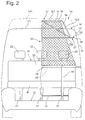
- a combination vehicle or small van is shown in longitudinal section. You can see the body side wall 10 on the right in the direction of travel with side windows 11 and 12. Roof frame 13, vehicle roof 14, vehicle floor 15 and seating 16. The roof line of the vehicle roof 14 in the low roof version is 141 and the roof line in the vehicle roof 14 version is a high roof is marked with 142.
- the seating 16 arranged in the so-called passenger compartment 17 is shown in FIGS 2 to see the last three-seat bench 18 of a plurality of benches lined up one behind the other in the vehicle longitudinal direction.
- the seat 18, which consists of the seat part 19 and the backrest 20 in a known manner, is anchored to the vehicle floor 15 via three seat feet 21.
- Each seat of the three-seat bench 18 is equipped with a headrest 22. Behind the last seat 18, the passenger compartment 17 is adjoined without separation by a loading space 23 for receiving loads of any kind.
- the passenger compartment 17 is separated from the cargo space 23 by a flexible and detachable protective device 30 which is quick and easy to use Combined vehicle can be assembled and disassembled.
- the protective device 30 has a safety net 31 which is stretched between the passenger compartment 17 and the cargo space 23 between the vehicle roof 14 and the vehicle floor 15 and spans at least the area between the upper edge of the backrest 20 of the seat 18 and the vehicle roof 14.
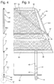
- the protective device 30 is shown in FIGS. 2 and 3 on one side in plan view and in FIGS. 1 and 4 in side view.
- the protective device 30 has a trapezoidal tubular frame 32, which is composed of an upper frame part 321, a lower frame part 322 and two obliquely extending side rails 323 connecting the frame parts 321, 322, and a lower cross tube 33, which is located behind the Backrest 20, approximately 200 mm below the upper edge of the backrest 20, extends from one body side wall 10 to the other body side wall 10.
- the height of the tubular frame 32 is made larger than the distance between the roof frame 13 and the roof line 142 in the design of the vehicle roof 14 as a high roof.
- Two cross struts 34 are used to stiffen the tubular frame 32, each extending approximately from the center of the upper frame part 321 to the junction of the lower frame part 322 with the two side rails 323.
- the safety net 31 is fastened to the upper frame part 321 via sewn-on upper loops 35 and to the lower cross tube 33 via the same lower loops 36.
- the lower frame part 322 carries self-aligning fastening elements 37, which are used to fasten the tubular frame 32 to the roof frame 13.
- the fastening elements 37 are designed as wire ropes 38 with snap hooks 39.
- eyelets 24 or so-called eyebolts are fastened to the roof frame 13, into which the snap hooks 39 can be hung.
- Two eyebolts or eyelets 24 are provided opposite each other in the vehicle transverse direction behind each seat 18 on the roof frame 13, so that the protective device 30 can be attached to different places in the vehicle and thus the zones of the passenger compartment 17 and the cargo space 23 defined by it are variable in size can be designed.
- Two belt straps 40 with belt tensioners 41 engage on the lower cross tube 33 and are anchored directly or indirectly to the vehicle floor 15 at the end remote from the cross tube (FIGS. 1-4).
- the tubular frame 32 is hooked onto the roof frame 13 with the snap hooks 39 fastened to the lower frame part 322 by means of the wire cables 38 in the two eyelets 24 located opposite one another in the transverse direction of the vehicle.
- the safety net 31 fastened at the end to the upper frame part 321 lies loosely on the lower frame part 322 and is deflected by the latter.
- the lower Frame part 322 faces load space 23, while safety net 31 covers lower frame part 322 as seen from passenger compartment 17.
- the lower cross tube 33 lies below the upper edge of the backrest 20 of the seat 18 on the backrest 20, the two belt straps 40 are anchored at the ends in the vehicle floor 15 in the middle or in the middle, and the safety net 31 is tensioned in the belt straps 40 by the two belt tensioners 41 .
- the resulting tensile forces force the tubular frame 32 to pivot about its self-aligning roof suspension points formed by the two wire ropes 38 and snap hooks 39 until the upper frame part 321 bears against the vehicle roof 14 or the roof cladding underneath.
- the protective device 30 can be installed and functions independently of whether the combination vehicle is designed with a high roof (roof line 142) or with a low roof (roof line 141).
- the belt tensioner 41 is supported in the belt straps when the safety net is tensioned 40 and by the load on the safety net 31 due to the forward pushing load of the tubular frame 32 on the vehicle roof 14.
- the low-roof version it is a bit flatter, in the high-roof version it is set a little steeper. The latter is indicated in Fig. 1 by dash-dotted representation of the tubular frame 32.
- the fixing of the two belt straps 40 acting on the lower cross tube 33 on the vehicle floor side can be designed differently.
- the two webbing straps 40 engaging the cross tube 33 are fixed at the end to an anchoring tube 42 which runs below the cross tube 33 in parallel and at a distance from it.
- This anchoring tube 42 is either fixed directly in the vehicle floor 15 at correspondingly provided anchoring points by means of anchoring elements or in corresponding anchoring points in the seat feet of the seat 18, which in turn are anchored to the vehicle floor 15.
- the anchoring elements 43 are designed as hooks 44, which are connected to the anchoring tube 42 via tension bands 45.
- the anchoring of a hook 44 in the vehicle floor 13 is shown enlarged in FIG. 5.
- wire brackets 46 executed, which are welded to the anchoring tube 42.
- wire brackets 46 are welded on as there are seat feet 21 on the seat 18 located in front of the protective device 30.
- shaped holes 27 are provided in the rear upper region, into which the wire brackets 46 are hung with angled wire ends on both sides of the seat base 21.
- the anchoring elements 43 described above for the anchoring tube 42 can alternatively be used. If, for example, not a three-seat bench 18 but only a two-seat bench is arranged in front of the protective device 30, the two described embodiments of the anchoring elements 43 are also used additively.
- the anchoring tube 42 is then hooked into the form holes 27 on the seat base 21 via the wire brackets 46, and on the right, the anchoring tube is anchored in the vehicle floor 15 via a drawstring 45 and hook 44. If the protective device 30 is arranged directly behind the driver and front passenger seats, the anchoring tube 42 is fastened to the seat boxes of the front seats via drawstrings 45 and hooks 44.
- This fastening element 37 is formed by a two-part holding unit, which enables the tubular frame 32 to pivot about the axis of its lower frame part 322 and thus to be supported on the vehicle roof 14 with its upper frame part 321.
- one part of the holding unit is composed of a bracket 47 fixed to the roof frame 13 of the vehicle and a bracket 48 which can be pivoted in the bracket 47 in the vertical direction.
- the tab 47 is a bent sheet metal part with a bent eye 471 and the bracket is bent as an approximately T-shaped wire bracket, the cross part 481 of which lies pivotably in the eye 471 and the middle part 482 has an opening 50.
- the central part 482 and the cross part 481 are angled at an obtuse angle of approximately 100 °.
- a through hole 51 alternatively two through holes arranged at a distance from one another, is provided in the tab 47, through which a cap screw 52 can be inserted.
- the head screw 52 indicated by dot-dash lines in FIG. 7 is screwed into a corresponding threaded hole in the roof frame 13.
- the second part of the holding unit consists of a bolt 49 with a bolt head 492 and a bolt end 491 bent at a right angle.
- the bolt 49 is inserted through the opening 50 in the middle part 482 of the bracket 48 and rests with its bolt head 492 on the top of the middle part 482.
- the right-angled bolt end 491 protrudes into the open end of the lower frame part 322 of the tubular frame 32 with rotational play, so that the lower frame part 322 can rotate on the two bolt ends 491 of two fastening elements 37 protruding left and right into the end ends.
- the protective device is dispensed with or if the device is clamped behind another row of seats between the two holding units, the two bolts 49 are pulled out of the two no longer required holding devices and the bracket 48 in the tab 47 is folded against the roof frame 13.
Landscapes
- Engineering & Computer Science (AREA)
- Mechanical Engineering (AREA)
- Body Structure For Vehicles (AREA)
Applications Claiming Priority (2)
| Application Number | Priority Date | Filing Date | Title |
|---|---|---|---|
| DE19619642A DE19619642C1 (de) | 1996-05-15 | 1996-05-15 | Schutzvorrichtung für Kombifahrzeuge |
| DE19619642 | 1996-05-15 |
Publications (2)
| Publication Number | Publication Date |
|---|---|
| EP0807555A2 true EP0807555A2 (fr) | 1997-11-19 |
| EP0807555A3 EP0807555A3 (fr) | 2000-10-04 |
Family
ID=7794432
Family Applications (1)
| Application Number | Title | Priority Date | Filing Date |
|---|---|---|---|
| EP97105006A Withdrawn EP0807555A3 (fr) | 1996-05-15 | 1997-03-25 | Dispositif de protection pour véhicules de type break |
Country Status (3)
| Country | Link |
|---|---|
| US (1) | US5839757A (fr) |
| EP (1) | EP0807555A3 (fr) |
| DE (1) | DE19619642C1 (fr) |
Families Citing this family (20)
| Publication number | Priority date | Publication date | Assignee | Title |
|---|---|---|---|---|
| DE19728550B4 (de) * | 1996-07-16 | 2009-02-05 | Volkswagen Ag | Ladegutsicherungsvorrichtung für einen Laderaum eines Kraftfahrzeugs |
| SE514855C2 (sv) * | 1998-04-20 | 2001-05-07 | Volvo Ab | Skyddsanordning för fordon |
| SE514565C2 (sv) * | 1999-07-15 | 2001-03-12 | Klippan Safety Ab | Kojarrangemang i en lastbilshytt |
| US6345944B1 (en) | 1999-09-29 | 2002-02-12 | Steven Florence | Cargo net for passenger vehicle |
| US20020056980A1 (en) | 2000-05-17 | 2002-05-16 | Saczalski Todd K. | Vehicle occupant safety net |
| US6502859B1 (en) * | 2001-06-18 | 2003-01-07 | Robert W. Svetlik | Automotive safety net system |
| DE10229815B4 (de) * | 2002-06-28 | 2006-12-14 | Bos Gmbh & Co. Kg | System zum Laderaumschutz von Fahrzeugen |
| DE10358425B4 (de) * | 2003-12-13 | 2007-08-30 | GM Global Technology Operations, Inc., Detroit | Längenvariable Befestigungsvorrichtung |
| US7637705B2 (en) * | 2004-02-27 | 2009-12-29 | Valeda Company | Track fitting with visual indicia of engagement |
| US7229238B2 (en) * | 2004-03-25 | 2007-06-12 | Valeda Company Llc | Wheelchair docking system |
| US20070018442A1 (en) * | 2005-07-22 | 2007-01-25 | Kwok Ming Y | Vehicle driver and passenger restraining device |
| US7287796B2 (en) * | 2006-02-22 | 2007-10-30 | Ford Global Technologies, Llc | Integrated cargo net for a vehicle |
| US8348332B2 (en) * | 2009-12-11 | 2013-01-08 | Honda Motor Co., Ltd. | Partition structure and installation structure for installation part |
| US20110188980A1 (en) * | 2010-01-31 | 2011-08-04 | Pumroy Joann | Gettie up thar |
| US9511734B2 (en) * | 2015-01-29 | 2016-12-06 | Ford Global Technologies, Llc | Passenger protection system |
| US10843799B2 (en) * | 2016-04-04 | 2020-11-24 | B/E Aerospace, Inc. | Contoured class divider |
| US10676194B2 (en) | 2016-04-04 | 2020-06-09 | B/E Aerospace, Inc. | Contoured class divider |
| US11066171B2 (en) * | 2016-04-04 | 2021-07-20 | B/E Aerospace, Inc. | Contoured class divider |
| US10919631B2 (en) * | 2018-10-29 | 2021-02-16 | Safran Cabin Inc. | Aircraft with multiple doors and multiple zones |
| US11034452B2 (en) * | 2018-10-29 | 2021-06-15 | Safran Cabin Inc. | Aircraft with staggered seating arrangement |
Family Cites Families (5)
| Publication number | Priority date | Publication date | Assignee | Title |
|---|---|---|---|---|
| US3423121A (en) * | 1967-02-10 | 1969-01-21 | Martin Lipkin | Protective partition against deceleration |
| DE4239472C1 (de) * | 1992-11-24 | 1994-03-31 | Butz Peter Verwaltung | Bahnförmige Rückhaltevorrichtung für den Innenraum von Kraftfahrzeugen |
| DE4328746C2 (de) * | 1993-08-26 | 1995-08-24 | Baumeister & Ostler Gmbh Co | Sicherheitsnetzanordnung |
| DE4438910C1 (de) * | 1994-11-03 | 1996-03-21 | Butz Peter Verwaltung | Rückhaltevorrichtung für den Laderaum von Kraftfahrzeugen, wie z. B. für Kombinationskraftwagen oder Großraum-Personenkraftwagen |
| DE4441610C2 (de) * | 1994-11-23 | 1997-10-02 | Baumeister & Ostler Gmbh Co | Sicherheitsnetzanordnung |
-
1996
- 1996-05-15 DE DE19619642A patent/DE19619642C1/de not_active Expired - Fee Related
-
1997
- 1997-03-25 EP EP97105006A patent/EP0807555A3/fr not_active Withdrawn
- 1997-05-14 US US08/856,027 patent/US5839757A/en not_active Expired - Fee Related
Also Published As
| Publication number | Publication date |
|---|---|
| DE19619642C1 (de) | 1997-05-22 |
| EP0807555A3 (fr) | 2000-10-04 |
| US5839757A (en) | 1998-11-24 |
Similar Documents
| Publication | Publication Date | Title |
|---|---|---|
| DE19619642C1 (de) | Schutzvorrichtung für Kombifahrzeuge | |
| EP0765252B1 (fr) | Banquette pour vehicules a moteur, notamment autocaravanes | |
| DE60305110T2 (de) | Einbaustruktur für Kindersitze | |
| DE102007002372B3 (de) | Sicherheitssitz ohne Seiteneinbauten | |
| EP2231473B1 (fr) | Siège de sécurité suspendu à des boucles de sangle de maintien s'étendant verticalement | |
| DE102007002371B3 (de) | Mit einem Schultergurtzeug versehener Sicherheitssitz ohne Seiteneinbauten | |
| EP2505428B1 (fr) | Fixation de ceinture sur le tube principal arrière du dossier, dans l'idéal sur le pied inférieur arrière | |
| DE19800072A1 (de) | Rückhaltesystem für einen in einem Kraftfahrzeug mitgeführten Kindersitz | |
| DE102019119131B4 (de) | Trennnetz | |
| DE19634104C1 (de) | Netz zur Lagesicherung von Ladegut auf Ladeflächen von Fahrzeugen | |
| DE19522686C1 (de) | Dreipunktgurtsystem für ein Kraftfahrzeug | |
| EP3321126B1 (fr) | Support de ceinture pour un siège de véhicule | |
| EP3398840A1 (fr) | Dispositif destiné à agencer un système de retenue des personnes dans un véhicule | |
| DE69924444T3 (de) | Schutzvorrichtung insbesondere Sicherheitsnetz für Kraftfahrzeuge | |
| DE202019003285U1 (de) | Befestigungsvorrichtung eines Rückhaltenetzes für Lasten in einem Kraftfahrzeug | |
| DE2656249C3 (de) | Aufprallschutzvorrichtung für die Insassen von Fahrzeugen, insbesondere von Personenkraftfahrzeugen | |
| DE10358425B4 (de) | Längenvariable Befestigungsvorrichtung | |
| EP4223596B1 (fr) | Cadre de ceinture pour siège de véhicule | |
| DE10114409B4 (de) | Einrichtung und Verfahren zum Befestigen eines Transportguts auf der Ladefläche eines Transportfahrzeugs | |
| DE202017007028U1 (de) | Gurtgestell für einen Fahrzeugsitz | |
| DE9311587U1 (de) | Vorrichtung zum Schutz von Fahrzeuginsassen | |
| EP4371824A1 (fr) | Dispositif de séparation d'espace et véhicule automobile | |
| DE202016105188U1 (de) | Spanneinrichtung und Ladungssicherungssystem | |
| DE102010047120A1 (de) | Struktur für einen Fahrzeugsitz | |
| DE20215934U1 (de) | Schutzvorrichtung für Kraftfahrzeuge zum Schutz vor Ladegut |
Legal Events
| Date | Code | Title | Description |
|---|---|---|---|
| PUAI | Public reference made under article 153(3) epc to a published international application that has entered the european phase |
Free format text: ORIGINAL CODE: 0009012 |
|
| AK | Designated contracting states |
Kind code of ref document: A2 Designated state(s): DE ES FR GB IT |
|
| RAP1 | Party data changed (applicant data changed or rights of an application transferred) |
Owner name: DAIMLERCHRYSLER AG |
|
| PUAL | Search report despatched |
Free format text: ORIGINAL CODE: 0009013 |
|
| AK | Designated contracting states |
Kind code of ref document: A3 Designated state(s): DE ES FR GB IT |
|
| 17P | Request for examination filed |
Effective date: 20010315 |
|
| GRAG | Despatch of communication of intention to grant |
Free format text: ORIGINAL CODE: EPIDOS AGRA |
|
| GRAG | Despatch of communication of intention to grant |
Free format text: ORIGINAL CODE: EPIDOS AGRA |
|
| STAA | Information on the status of an ep patent application or granted ep patent |
Free format text: STATUS: THE APPLICATION HAS BEEN WITHDRAWN |
|
| 17Q | First examination report despatched |
Effective date: 20010627 |
|
| 18W | Application withdrawn |
Withdrawal date: 20010721 |