EP0807453A1 - Vorderbackensystem für Schuhe auf Skis - Google Patents
Vorderbackensystem für Schuhe auf Skis Download PDFInfo
- Publication number
- EP0807453A1 EP0807453A1 EP97106532A EP97106532A EP0807453A1 EP 0807453 A1 EP0807453 A1 EP 0807453A1 EP 97106532 A EP97106532 A EP 97106532A EP 97106532 A EP97106532 A EP 97106532A EP 0807453 A1 EP0807453 A1 EP 0807453A1
- Authority
- EP
- European Patent Office
- Prior art keywords
- wing
- shoulder
- transmission member
- return
- flap
- Prior art date
- Legal status (The legal status is an assumption and is not a legal conclusion. Google has not performed a legal analysis and makes no representation as to the accuracy of the status listed.)
- Granted
Links
Images


Classifications
-
- A—HUMAN NECESSITIES
- A63—SPORTS; GAMES; AMUSEMENTS
- A63C—SKATES; SKIS; ROLLER SKATES; DESIGN OR LAYOUT OF COURTS, RINKS OR THE LIKE
- A63C9/00—Ski bindings
- A63C9/08—Ski bindings yieldable or self-releasing in the event of an accident, i.e. safety bindings
- A63C9/085—Ski bindings yieldable or self-releasing in the event of an accident, i.e. safety bindings with sole hold-downs, e.g. swingable
- A63C9/08507—Ski bindings yieldable or self-releasing in the event of an accident, i.e. safety bindings with sole hold-downs, e.g. swingable with a plurality of mobile jaws
- A63C9/08521—Ski bindings yieldable or self-releasing in the event of an accident, i.e. safety bindings with sole hold-downs, e.g. swingable with a plurality of mobile jaws pivoting about a vertical axis, e.g. side release
-
- A—HUMAN NECESSITIES
- A63—SPORTS; GAMES; AMUSEMENTS
- A63C—SKATES; SKIS; ROLLER SKATES; DESIGN OR LAYOUT OF COURTS, RINKS OR THE LIKE
- A63C9/00—Ski bindings
- A63C9/08—Ski bindings yieldable or self-releasing in the event of an accident, i.e. safety bindings
- A63C9/085—Ski bindings yieldable or self-releasing in the event of an accident, i.e. safety bindings with sole hold-downs, e.g. swingable
- A63C9/08557—Details of the release mechanism
- A63C9/08564—Details of the release mechanism using cam or slide surface
Definitions
- the invention relates to a shoe retention element on a ski.
- the invention relates to a front retaining element which is designed to releasably retain the front of a shoe.
- the element has a jaw which is movable against the restoring force opposed to it by an elastic return means, for example a spring.
- the invention relates to those whose triggering is asymmetrical, that is to say that they release the shoe more easily on one side than on the other. It is known in fact that the leg of a skier is capable of enduring higher torsions for a rotation of the front of the foot towards the outside than for a rotation towards the other foot. It therefore appeared interesting to produce retaining elements which take this asymmetry into account.
- Patent applications published under the numbers FR 1 503 849, FR 1 503 847 describe such elements which release the shoe asymmetrically.
- An object of the invention is to improve this type of retaining element by making its operation asymmetrical by simple modifications of its construction.
- the retaining element comprises a base designed to be secured to the ski, a body connected to the base, the body having two articulation axes for two retaining wings, the retaining wings having a return of wing beyond the hinge axis, a return spring housed in the body, a connecting member between the spring and the wing returns. It also includes an asymmetrical member in the connection chain between the spring and the wings.
- Figure 1 shows a side traditional retention element of the type concerned by the invention.
- FIG. 2 is a side view in section of the retaining element of FIG. 1.
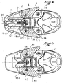
- Figure 3 shows two half views of the retainer of Figure 1 cut by section planes located at different altitudes.
- Figure 4 illustrates in top view and in section a retaining element according to a first embodiment of the invention.
- FIG. 5 relates to another embodiment of the invention.
- FIG. 6 illustrates the operating mode of the element shown in FIG. 5.
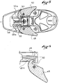
- Figure 7 relates to another embodiment of the invention.
- FIG. 8 represents in perspective the intermediate flap of FIG. 6.
- FIG. 9 illustrates the operating mode of the element in FIG. 7.
- the front fixing element 1 represented in FIGS. 1 to 3 is essentially known from the French patent application published under the number FR 2 640 516.
- the base has a "U" shape open towards the rear, with two lateral branches 3a and 3b.
- the body is movable vertically relative to the base by a deformable link, located in zone 9 at the junction between the body and the base.
- the body and the base are connected continuously by this deformable zone and form a one-piece element.
- the body 2 carries a jaw 4 for retaining the front end of the shoe.
- the jaw 4 comprises two lateral retaining wings 5 and 6, respectively articulated to the body 2 around axes 7 and 8.
- the jaw 4 also includes a sole clamp 12 for vertical retention of the shoe.
- the wings 5 and 6 are movable in response to the stresses of the shoe, against the restoring force applied to them by a spring 15.
- the spring 15 is housed in the body. It acts on a piston 16 also housed and guided in the body for a longitudinal translational movement.
- the figures show that the piston is housed and guided in a housing 17 of the body, and that the spring is engaged inside the piston. Its front end bears against the bottom of the piston, located on the front side of the fixing element.
- a screw 20, the head of which is retained at the front of the body moreover passes through the piston and the spring, and has a nut 21 towards the rear which retains the rear end of the spring.
- a rotation of the screw drives the spring in translation, which makes it possible to adjust the initial compression of the spring.
- the wings 5 and 6 have, beyond their axis of articulation to the body 7 and 8, a return 5a, 6a, which drives the piston 16 backwards, bearing against a shoulder 23 situated in the upper rear part of the piston 16.
- the element 1 has a compensation mechanism which reduces the restoring force that the spring 15 exerts on the wings 5 and 6.
- This mechanism comprises an articulated rocker 30 which is partly housed between the branches 3a and 3b of the base 3.
- the rocker is articulated around an axis 32 carried by these branches.
- the rocker 30 has an approximately horizontal arm 33 which is accessible on the rear of the fixing element between the branches 3a and 3b of the base.
- the rocker 30 also has an approximately vertical arm formed by two lateral pads which pass on each side of the piston 16, and which each carry on a shoulder 37 which the piston presents under the shoulder 23 of the wings. Only the shoe 35 is partially visible in the figures.
- a connecting rod 36 also connects the rocker 30 to the rear part of the body 2.
- the articulation of the rod 36 to the rocker 30 is located in front of the axis 32.
- the rod transmits to the rocker 30, and therefore to the piston 16 , the elevation movements of the body which occur in particular when the shoe is vertically stressed in the jaw.
- the element has behind the jaw a support plate 40 intended to receive the front of the shoe sole.
- the front part of the pedal is movable vertically, and overhangs the horizontal arm 33 of the rocker 30.
- a spring 51 ensures the elastic return towards the top of the front of the pedal.
- FIG. 4 illustrates a first embodiment of the invention.
- one of the two wings has a shorter return than the other so that the wings stress the piston with different lifting arms.
- FIG. 4 a retaining element is shown with the return 45a of the wing 45 shorter than the return of the other wing 46.
- the wing 45 attacks the piston with a shorter lifting arm, from which it follows that this wing 45 will be easier to open than the other wing 46.
- the axis offset could also have two components, inward and forward, to both increase the lever arm with which the shoe requests the wing, and decrease the lever arm with which the wing attacks the piston.
- FIG. 5 illustrates another variant implementation of the invention.
- the wing which has the lowest resistance to opening in this case the wing 48, has a wing return 48a whose bearing face against the shoulder of the piston is cut as a bevelled ramp which has an oblique bearing face with respect to a longitudinal direction.
- Piston 49 has a support shoulder 50 which is designed to cooperate with the support face of the ramp so that the contact surface between the wing return and the shoulder moves along the beveled ramp during the wing rotation.
- the shape of the support shoulder takes into account the shape of the wing ramp, and also takes into account the fact that the wing return moves in a circular motion, but that it animates the shoulder d 'a movement directed in a longitudinal direction.
- the shoulder has a leading edge for the return of a relatively thin and rounded wing.
- the wing return slides on the shoulder of the piston, and, therefore, in a longitudinal direction, the wing return has a linear movement. greater amplitude than the linear movement of the piston that the return causes.
- the release of the boot on the side of the wing 48 is obtained for a compression of the spring weaker than on the side of the other wing.
- Figure 6 shows the wing 48 in the open position, with its return 48a which has slid along the shoulder due to its rotation about the axis of the wing.
- any other suitable shape is suitable for the contact surfaces of the wing beak and the shoulder, provided that, in a longitudinal direction, a relative movement of the return is obtained with respect to the piston.
- the other wing 52 of the retaining element has a traditional support with a wing return 52a bearing against a transverse shoulder 53 of the piston.
- Figures 7 to 9 show another embodiment of the invention.
- the piston 60 has in its upper part a transverse support shoulder 61, which provides support for the two returns 62a and 63a of the wings 62 and 63. Between the transverse shoulder and the returns wing is interposed a movable flap 65.
- the flap is more particularly visible in Figure 8.
- On the wing return side it has a bearing face with two bearing zones 66 and 67, substantially in the extension on the other, one for each wing return.
- the flap On the other side, the flap carries two support zones 68 and 69, which form between them a dihedral of angle greater than a flat angle, so that a portion of the flap is bevelled.
- the faces 67 and 69 are substantially parallel to one another.
- the flap carries an edge 70 or any other appropriate means of bearing against the transverse shoulder 53 of the piston, and of articulation around a vertical direction.
- the edge is offset on the side where the flap is bevelled without however exceeding the level of the support of the wing return 62a against zone 66.
- the shoulder has a groove or all other suitable means to receive edge 70 from shutter. Any other means of support and articulation between these two elements is also suitable.
- the wings 62 and 63 each have a support stop which defines their rest position.
- This stop is formed for example by the supports of the internal face 72, 73 of the wings against stops integral with the body. These stops are not shown in the figures. In known manner, these stops can be formed by vertical partitions which connect the upper part and the lower part of the body.
- the spring In the rest position, the spring returns the wings to their rest position.
- the flap 65 is held with its face 69 in abutment against the transverse shoulder 61.
- the wing return 63a carries with it the flap, the two parallel faces 67 and 69 of which are pinched between the wing return and the shoulder transverse. The movement of the wing return in a longitudinal direction is transmitted directly to the piston.
- the displacement of the piston and the resistance force that the piston opposes to the opening of the wing are reduced by the ratio of the lever arms between the various supports of the flap.
- the wing 63 which is located on the side of the bevel of the flap opens more easily than the other wing.
- the position of the edge relative to the bearing zones of the two wing returns determines the ratio of the lever arms and therefore the ratio of reduction in forces.
- the bevel angle of the flap determines with the position of the edge 70 the opening stroke of the wing 62 beyond which the face 68 of the flap 65 comes to bear against the shoulder. At this stage of tilting of the flap, the movement of the flap becomes equal to that of the piston.
- the face 68 of the flap could be entirely or partially curved, so as to have a variable speed reduction between the linear speed of the wing return and that of the piston.
- the face 66 could also be curved or have a ramp shape to compensate for the tilting of the flap 65 and the relative movement between the wing return 62a and the flap 65 during the opening of the wing.
- the piston could be replaced by a tie rod or any other suitable member for transmitting force guided relative to the body.
- each of the elements has an asymmetry of the same nature, which is exerted in reverse, that is to say, for example, which reduces the effort retaining external wings.
Landscapes
- Footwear And Its Accessory, Manufacturing Method And Apparatuses (AREA)
Applications Claiming Priority (2)
| Application Number | Priority Date | Filing Date | Title |
|---|---|---|---|
| FR9606327 | 1996-05-15 | ||
| FR9606327A FR2748668B1 (fr) | 1996-05-15 | 1996-05-15 | Element de retenue de l'avant d'une chaussure sur un ski |
Publications (2)
| Publication Number | Publication Date |
|---|---|
| EP0807453A1 true EP0807453A1 (de) | 1997-11-19 |
| EP0807453B1 EP0807453B1 (de) | 2003-04-09 |
Family
ID=9492337
Family Applications (1)
| Application Number | Title | Priority Date | Filing Date |
|---|---|---|---|
| EP97106532A Expired - Lifetime EP0807453B1 (de) | 1996-05-15 | 1997-04-21 | Vorderbackensystem für Schuhe auf Skis |
Country Status (4)
| Country | Link |
|---|---|
| EP (1) | EP0807453B1 (de) |
| AT (1) | ATE236691T1 (de) |
| DE (1) | DE69720584T2 (de) |
| FR (1) | FR2748668B1 (de) |
Cited By (3)
| Publication number | Priority date | Publication date | Assignee | Title |
|---|---|---|---|---|
| FR2806639A1 (fr) * | 2000-03-23 | 2001-09-28 | Emery Sa | Perfectionnement pour dispositif de retenue d'une chaussure de ski sur un ski |
| EP1151765A1 (de) * | 2000-05-04 | 2001-11-07 | Salomon S.A. | Vorderbacken einer Skibindung |
| US6585282B2 (en) | 2000-05-04 | 2003-07-01 | Salomon S.A. | Element for retaining the front portion of a boot on a ski |
Citations (4)
| Publication number | Priority date | Publication date | Assignee | Title |
|---|---|---|---|---|
| DE1807074A1 (de) * | 1968-11-05 | 1970-05-27 | Augustin Dr Ing Dietmar | Asymmetrische Schisicherheitsbindungen (Vorderbacken) gegen Drehstuerze |
| EP0302309A2 (de) * | 1987-08-03 | 1989-02-08 | Marker Deutschland GmbH | Vorderbacken für Sicherheits-Skibindungen |
| EP0692288A1 (de) * | 1994-07-13 | 1996-01-17 | Salomon S.A. | Bindung für Alpinski |
| EP0712647A1 (de) * | 1994-11-21 | 1996-05-22 | Salomon S.A. | Haltevorrichtung für Skischuhe auf Gleitbretter |
-
1996
- 1996-05-15 FR FR9606327A patent/FR2748668B1/fr not_active Expired - Fee Related
-
1997
- 1997-04-21 AT AT97106532T patent/ATE236691T1/de not_active IP Right Cessation
- 1997-04-21 EP EP97106532A patent/EP0807453B1/de not_active Expired - Lifetime
- 1997-04-21 DE DE69720584T patent/DE69720584T2/de not_active Expired - Fee Related
Patent Citations (4)
| Publication number | Priority date | Publication date | Assignee | Title |
|---|---|---|---|---|
| DE1807074A1 (de) * | 1968-11-05 | 1970-05-27 | Augustin Dr Ing Dietmar | Asymmetrische Schisicherheitsbindungen (Vorderbacken) gegen Drehstuerze |
| EP0302309A2 (de) * | 1987-08-03 | 1989-02-08 | Marker Deutschland GmbH | Vorderbacken für Sicherheits-Skibindungen |
| EP0692288A1 (de) * | 1994-07-13 | 1996-01-17 | Salomon S.A. | Bindung für Alpinski |
| EP0712647A1 (de) * | 1994-11-21 | 1996-05-22 | Salomon S.A. | Haltevorrichtung für Skischuhe auf Gleitbretter |
Cited By (7)
| Publication number | Priority date | Publication date | Assignee | Title |
|---|---|---|---|---|
| FR2806639A1 (fr) * | 2000-03-23 | 2001-09-28 | Emery Sa | Perfectionnement pour dispositif de retenue d'une chaussure de ski sur un ski |
| EP1138355A1 (de) * | 2000-03-23 | 2001-10-04 | Emery S.A. | Vorrichtung zum Befestigen eines Schischuhes auf einem Schi |
| US6550800B2 (en) | 2000-03-23 | 2003-04-22 | Emery, Sa | Retaining device of a ski boot on a ski |
| EP1151765A1 (de) * | 2000-05-04 | 2001-11-07 | Salomon S.A. | Vorderbacken einer Skibindung |
| FR2808453A1 (fr) * | 2000-05-04 | 2001-11-09 | Salomon Sa | Element de retenue de l'avant d'une chaussure sur un ski |
| US6585283B2 (en) | 2000-05-04 | 2003-07-01 | Salomon S.A. | Element for retaining the front portion of a boot on a ski |
| US6585282B2 (en) | 2000-05-04 | 2003-07-01 | Salomon S.A. | Element for retaining the front portion of a boot on a ski |
Also Published As
| Publication number | Publication date |
|---|---|
| FR2748668B1 (fr) | 1998-07-03 |
| DE69720584D1 (de) | 2003-05-15 |
| EP0807453B1 (de) | 2003-04-09 |
| ATE236691T1 (de) | 2003-04-15 |
| DE69720584T2 (de) | 2003-11-27 |
| FR2748668A1 (fr) | 1997-11-21 |
Similar Documents
| Publication | Publication Date | Title |
|---|---|---|
| CH670190A5 (de) | ||
| CH656292A5 (fr) | Chaussure de ski. | |
| EP0692288B1 (de) | Bindung für Alpinski | |
| FR2684885A1 (fr) | Dispositif visant a repartir la pression d'un ski sur une surface de glisse. | |
| EP0653231B1 (de) | Bindungselement für Skier | |
| EP0241360A1 (de) | Sicherheitsskibindung | |
| CH667977A5 (fr) | Chaussure de ski a entree arriere. | |
| EP0807453B1 (de) | Vorderbackensystem für Schuhe auf Skis | |
| EP0634196B1 (de) | Bindungselement für einen alphinen Ski | |
| CH673229A5 (de) | ||
| CH673400A5 (de) | ||
| CH673776A5 (de) | ||
| CH660976A5 (fr) | Fixation de securite pour ski. | |
| FR2755868A1 (fr) | Dispositif d'appui d'une chaussure de ski sur un ski | |
| EP1151765B1 (de) | Vorderbacken einer Skibindung | |
| EP0820789B1 (de) | Schuh-Ski Kombination | |
| EP0700699B1 (de) | Skibindung | |
| EP0627947B1 (de) | Sohlenplatte verbunden mit einem vorderbacken einer sicherheitsskibindung | |
| EP1721641B1 (de) | Bindungsvorrichtung mit einstellbarer Rückhubenergie | |
| EP0076176A1 (de) | Skibremse | |
| FR2598933A1 (fr) | Fixation de securite d'une chaussure sur un ski | |
| EP1138354B1 (de) | Vorrichtung zur Halterung eines Schuhvorderteils auf einem Ski | |
| FR2595257A1 (fr) | Frein pour monoski | |
| FR2732899A1 (fr) | Element de retenue d'une chaussure sur un ski | |
| FR2625687A1 (fr) | Fixation de securite de ski alpin |
Legal Events
| Date | Code | Title | Description |
|---|---|---|---|
| PUAI | Public reference made under article 153(3) epc to a published international application that has entered the european phase |
Free format text: ORIGINAL CODE: 0009012 |
|
| AK | Designated contracting states |
Kind code of ref document: A1 Designated state(s): AT CH DE IT LI |
|
| 17P | Request for examination filed |
Effective date: 19980326 |
|
| GRAH | Despatch of communication of intention to grant a patent |
Free format text: ORIGINAL CODE: EPIDOS IGRA |
|
| GRAH | Despatch of communication of intention to grant a patent |
Free format text: ORIGINAL CODE: EPIDOS IGRA |
|
| GRAA | (expected) grant |
Free format text: ORIGINAL CODE: 0009210 |
|
| AK | Designated contracting states |
Designated state(s): AT CH DE IT LI |
|
| PG25 | Lapsed in a contracting state [announced via postgrant information from national office to epo] |
Ref country code: IT Free format text: LAPSE BECAUSE OF FAILURE TO SUBMIT A TRANSLATION OF THE DESCRIPTION OR TO PAY THE FEE WITHIN THE PRESCRIBED TIME-LIMIT;WARNING: LAPSES OF ITALIAN PATENTS WITH EFFECTIVE DATE BEFORE 2007 MAY HAVE OCCURRED AT ANY TIME BEFORE 2007. THE CORRECT EFFECTIVE DATE MAY BE DIFFERENT FROM THE ONE RECORDED. Effective date: 20030409 |
|
| REG | Reference to a national code |
Ref country code: CH Ref legal event code: EP |
|
| PGFP | Annual fee paid to national office [announced via postgrant information from national office to epo] |
Ref country code: CH Payment date: 20030502 Year of fee payment: 7 |
|
| PLBE | No opposition filed within time limit |
Free format text: ORIGINAL CODE: 0009261 |
|
| STAA | Information on the status of an ep patent application or granted ep patent |
Free format text: STATUS: NO OPPOSITION FILED WITHIN TIME LIMIT |
|
| 26N | No opposition filed |
Effective date: 20040112 |
|
| PG25 | Lapsed in a contracting state [announced via postgrant information from national office to epo] |
Ref country code: LI Free format text: LAPSE BECAUSE OF NON-PAYMENT OF DUE FEES Effective date: 20040430 Ref country code: CH Free format text: LAPSE BECAUSE OF NON-PAYMENT OF DUE FEES Effective date: 20040430 |
|
| REG | Reference to a national code |
Ref country code: CH Ref legal event code: PL |
|
| PGFP | Annual fee paid to national office [announced via postgrant information from national office to epo] |
Ref country code: AT Payment date: 20050413 Year of fee payment: 9 |
|
| PGFP | Annual fee paid to national office [announced via postgrant information from national office to epo] |
Ref country code: DE Payment date: 20050414 Year of fee payment: 9 |
|
| PG25 | Lapsed in a contracting state [announced via postgrant information from national office to epo] |
Ref country code: AT Free format text: LAPSE BECAUSE OF NON-PAYMENT OF DUE FEES Effective date: 20060421 |
|
| PG25 | Lapsed in a contracting state [announced via postgrant information from national office to epo] |
Ref country code: DE Free format text: LAPSE BECAUSE OF NON-PAYMENT OF DUE FEES Effective date: 20061101 |