EP0653231B1 - Bindungselement für Skier - Google Patents
Bindungselement für Skier Download PDFInfo
- Publication number
- EP0653231B1 EP0653231B1 EP94116605A EP94116605A EP0653231B1 EP 0653231 B1 EP0653231 B1 EP 0653231B1 EP 94116605 A EP94116605 A EP 94116605A EP 94116605 A EP94116605 A EP 94116605A EP 0653231 B1 EP0653231 B1 EP 0653231B1
- Authority
- EP
- European Patent Office
- Prior art keywords
- jaw
- support plate
- sole
- support
- base
- Prior art date
- Legal status (The legal status is an assumption and is not a legal conclusion. Google has not performed a legal analysis and makes no representation as to the accuracy of the status listed.)
- Expired - Lifetime
Links
Images


Classifications
-
- A—HUMAN NECESSITIES
- A63—SPORTS; GAMES; AMUSEMENTS
- A63C—SKATES; SKIS; ROLLER SKATES; DESIGN OR LAYOUT OF COURTS, RINKS OR THE LIKE
- A63C9/00—Ski bindings
- A63C9/08—Ski bindings yieldable or self-releasing in the event of an accident, i.e. safety bindings
- A63C9/085—Ski bindings yieldable or self-releasing in the event of an accident, i.e. safety bindings with sole hold-downs, e.g. swingable
- A63C9/08535—Ski bindings yieldable or self-releasing in the event of an accident, i.e. safety bindings with sole hold-downs, e.g. swingable with a mobile body or base or single jaw
- A63C9/0855—Ski bindings yieldable or self-releasing in the event of an accident, i.e. safety bindings with sole hold-downs, e.g. swingable with a mobile body or base or single jaw pivoting about a vertical axis
-
- A—HUMAN NECESSITIES
- A63—SPORTS; GAMES; AMUSEMENTS
- A63C—SKATES; SKIS; ROLLER SKATES; DESIGN OR LAYOUT OF COURTS, RINKS OR THE LIKE
- A63C9/00—Ski bindings
- A63C9/08—Ski bindings yieldable or self-releasing in the event of an accident, i.e. safety bindings
- A63C9/085—Ski bindings yieldable or self-releasing in the event of an accident, i.e. safety bindings with sole hold-downs, e.g. swingable
- A63C9/08507—Ski bindings yieldable or self-releasing in the event of an accident, i.e. safety bindings with sole hold-downs, e.g. swingable with a plurality of mobile jaws
- A63C9/08521—Ski bindings yieldable or self-releasing in the event of an accident, i.e. safety bindings with sole hold-downs, e.g. swingable with a plurality of mobile jaws pivoting about a vertical axis, e.g. side release
-
- A—HUMAN NECESSITIES
- A63—SPORTS; GAMES; AMUSEMENTS
- A63C—SKATES; SKIS; ROLLER SKATES; DESIGN OR LAYOUT OF COURTS, RINKS OR THE LIKE
- A63C9/00—Ski bindings
- A63C9/08—Ski bindings yieldable or self-releasing in the event of an accident, i.e. safety bindings
- A63C9/085—Ski bindings yieldable or self-releasing in the event of an accident, i.e. safety bindings with sole hold-downs, e.g. swingable
- A63C9/08535—Ski bindings yieldable or self-releasing in the event of an accident, i.e. safety bindings with sole hold-downs, e.g. swingable with a mobile body or base or single jaw
- A63C9/08542—Ski bindings yieldable or self-releasing in the event of an accident, i.e. safety bindings with sole hold-downs, e.g. swingable with a mobile body or base or single jaw pivoting about a transversal axis
-
- A—HUMAN NECESSITIES
- A63—SPORTS; GAMES; AMUSEMENTS
- A63C—SKATES; SKIS; ROLLER SKATES; DESIGN OR LAYOUT OF COURTS, RINKS OR THE LIKE
- A63C9/00—Ski bindings
- A63C9/08—Ski bindings yieldable or self-releasing in the event of an accident, i.e. safety bindings
- A63C9/085—Ski bindings yieldable or self-releasing in the event of an accident, i.e. safety bindings with sole hold-downs, e.g. swingable
- A63C9/08557—Details of the release mechanism
- A63C9/08564—Details of the release mechanism using cam or slide surface
-
- A—HUMAN NECESSITIES
- A63—SPORTS; GAMES; AMUSEMENTS
- A63C—SKATES; SKIS; ROLLER SKATES; DESIGN OR LAYOUT OF COURTS, RINKS OR THE LIKE
- A63C9/00—Ski bindings
- A63C9/08—Ski bindings yieldable or self-releasing in the event of an accident, i.e. safety bindings
- A63C9/085—Ski bindings yieldable or self-releasing in the event of an accident, i.e. safety bindings with sole hold-downs, e.g. swingable
- A63C9/08557—Details of the release mechanism
- A63C9/08571—Details of the release mechanism using axis and lever
-
- A—HUMAN NECESSITIES
- A63—SPORTS; GAMES; AMUSEMENTS
- A63C—SKATES; SKIS; ROLLER SKATES; DESIGN OR LAYOUT OF COURTS, RINKS OR THE LIKE
- A63C9/00—Ski bindings
- A63C9/001—Anti-friction devices
-
- A—HUMAN NECESSITIES
- A63—SPORTS; GAMES; AMUSEMENTS
- A63C—SKATES; SKIS; ROLLER SKATES; DESIGN OR LAYOUT OF COURTS, RINKS OR THE LIKE
- A63C9/00—Ski bindings
- A63C9/08—Ski bindings yieldable or self-releasing in the event of an accident, i.e. safety bindings
- A63C9/084—Ski bindings yieldable or self-releasing in the event of an accident, i.e. safety bindings with heel hold-downs, e.g. swingable
- A63C9/0841—Ski bindings yieldable or self-releasing in the event of an accident, i.e. safety bindings with heel hold-downs, e.g. swingable with a single jaw
- A63C9/0842—Ski bindings yieldable or self-releasing in the event of an accident, i.e. safety bindings with heel hold-downs, e.g. swingable with a single jaw the jaw pivoting on the body or base about a transverse axis
-
- A—HUMAN NECESSITIES
- A63—SPORTS; GAMES; AMUSEMENTS
- A63C—SKATES; SKIS; ROLLER SKATES; DESIGN OR LAYOUT OF COURTS, RINKS OR THE LIKE
- A63C9/00—Ski bindings
- A63C9/08—Ski bindings yieldable or self-releasing in the event of an accident, i.e. safety bindings
- A63C9/084—Ski bindings yieldable or self-releasing in the event of an accident, i.e. safety bindings with heel hold-downs, e.g. swingable
- A63C9/0844—Ski bindings yieldable or self-releasing in the event of an accident, i.e. safety bindings with heel hold-downs, e.g. swingable the body pivoting about a transverse axis
-
- A—HUMAN NECESSITIES
- A63—SPORTS; GAMES; AMUSEMENTS
- A63C—SKATES; SKIS; ROLLER SKATES; DESIGN OR LAYOUT OF COURTS, RINKS OR THE LIKE
- A63C9/00—Ski bindings
- A63C9/08—Ski bindings yieldable or self-releasing in the event of an accident, i.e. safety bindings
- A63C9/084—Ski bindings yieldable or self-releasing in the event of an accident, i.e. safety bindings with heel hold-downs, e.g. swingable
- A63C9/0845—Ski bindings yieldable or self-releasing in the event of an accident, i.e. safety bindings with heel hold-downs, e.g. swingable the body or base or a jaw pivoting about a vertical axis, i.e. side release
Definitions
- the invention relates to an alpine ski binding element, intended to retain a boot bearing on a ski, and to release it in the event of excessive stress.
- Each retaining element has a jaw carried by a body, which is movable against the restoring force exerted by an energy spring, generally a compression spring.
- the invention relates more particularly to a front fixing element.
- the front binding element reacts to a lateral stress on the front end of the shoe. Such stress results from a stress in pure torsion on the skier's leg. When the fall is complex, such an element reacts to the lateral component of the stress exerted by the shoe.
- fastening elements are additionally equipped with compensation mechanisms.
- certain fastening elements react to a vertical upward stress.
- Such stress corresponds to a fall towards the rear of the skier.
- the European patent application published under the number 102 868 describes for example such a fixation.
- bindings have a compensation mechanism which reacts in the event of torsional stress combined with a forward fall of the skier.
- a compensation mechanism which reacts in the event of torsional stress combined with a forward fall of the skier.
- This mechanism comprises a support plate for the shoe which is vertically movable, the movement of which is caused by a vertical downward pressure of the shoe lowers the restoring force that the spring exerts on the jaw.
- One of the objects of the invention is to provide a fastening element which releases the shoe, in particular in the case of a pre-twist fall where the lateral component is relatively weak.
- Another object of the invention is to propose a fixing element which is relatively simple to construct.
- the support element forms for the shoe a tilting axis oriented longitudinally and located in the middle part of the sole, and that the vertical distance between the support element and the sole clamp is substantially equal to the thickness of the shoe sole, so that a twist of the shoe in the binding element results in a tilting of the shoe around the support element, and the edge of the sole which rises biases vertically towards the top the sole clamp.
- the shoe rests down against the retaining element, and in the event of rolling stress causing a twist of the shoe, the shoe rocks around the support element.
- the part of the sole which rises biases the sole clamp upwards, which activates the compensation mechanism provided for the rear fall.
- the support plate is itself connected to second compensation means which transmit to the spring reminders to the roll stresses of the support plate. These stresses exert on the spring a compensating force which is added to that generated by the sole clamp.
- an element among the base, the body or the jaw is disengageable relative to the element which carries it or on which it is mounted, and a circuit for control actuates the declutching beyond a determined roll tilting stroke of the support plate.
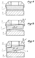
- Figures 1 and 2 show in front view and in section, the front end of a shoe pinched between the jaw of the fastening element and the support plate and illustrate the prior art.
- Figure 3 is a view similar to Figure 2 which generally illustrates the invention.
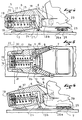
- Figure 4 is a side view in partial section of a fastening element implementing the general principle of the invention.
- FIG. 5 is a top view, in partial section of the fixing element of FIG. 4.
- FIG. 6 illustrates the operating mode of the fixing element of FIG. 4.
- FIG. 7 illustrates the mode of action of the shoe on the fastening element of FIG. 4.
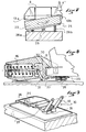
- FIG. 8 shows a fastening element in side view and in partial section according to another embodiment of the invention.
- Figure 9 is a partial perspective view of the fastener of Figure 8 at the support plate.
- FIG. 10 illustrates the operating mode of the fixing element of FIG. 8.
- FIG. 11 shows in side view and in partial section an attachment element according to an alternative embodiment of the invention.
- Figure 12 is a top view of the fastener of Figure 11 at the support plate.
- FIG. 13 illustrates the operation of the fixing element of FIG. 11.
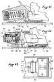
- Figure 14 shows in side view and in partial section a fastening element according to another embodiment of the invention.
- FIG. 15 is a top view in section of the fixing element of FIG. 14.
- Figure 16 is a top view in section at a lower level.
- FIG. 17 is a perspective view of the rocker of the fixing element in FIG. 14.
- FIGs 18 and 19 illustrate the mode of operation of the fastener of Figure 14.
- Figure 20 shows schematically an alternative embodiment.
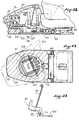
- FIGS 21 to 23 illustrate another embodiment of the invention.
- Figure 1 shows the front end 1 of a shoe sole which is pinched between the jaw 2 of a fastening element and a support plate 3 on which it rests.
- the fastening element which carries the jaw 2 is equipped with a compensation mechanism for rear fall, that is to say a vertical upward bias exerted on the jaw decreases the restoring force which is necessary overcome to cause the lateral opening of the jaw until the release of the shoe.
- Such compensation mechanisms are known, and some will be described in more detail with the different embodiments chosen to illustrate the invention.
- the support plate 3 of FIG. 2 is traditional, that is to say that it is immobile or else it can be lowered vertically in response to the stresses of the shoe oriented downwards.
- FIG. 2 shows the sole of shoe 1 animated by a twisting movement under the effect for example of a moment around a longitudinal axis which has been illustrated at "M".
- the shoe rocks by taking support by one of its lateral edges on the support plate, and by urging vertically upward the jaw with its other lateral edge. Illustrated in “F” the vertical stress that the shoe exerts on the jaw. It is this force F which activates the compensation mechanism and causes a reduction in the lateral retention force of the jaw.
- Figure 3 illustrates the present invention.
- the shoe sole no longer rests on a support plate but on a support element 4 which forms a vertical downward retention for the shoe sole as well as a longitudinal and central tilting axis, located towards the middle of the width of the sole.
- Figure 3 shows this support element in the form of a bead.
- the support element can also be constituted by a support plate articulated around a longitudinal axis, or by any other means forming a vertical support for the sole and a lateral tilting axis.
- a moment M of the same axis and same amplitude as the previous one causes the boot to tilt around the support element 4.
- the edge of the sole which rises, this time induces on the jaw a vertical force F 'which activates the rear compensation mechanism.
- the force F ′ is greater than F, since the shoe rocks around the support element 4, and no longer around its other lateral edge.
- F ' is about twice F.
- a more intense force activates the compensation circuit for rear fall.
- this force opens the jaw further in a vertical direction.
- Figures 4 to 7 relate to a first embodiment of the invention.
- the fastening element 5 shown in these figures comprises a body 6 connected to a base 7 which is connected to the ski by any suitable means and for example by screws.
- the body 6 carries a jaw 8 for retaining the front end of the shoe.
- the jaw 8 comprises two lateral retaining wings 9 and 10, respectively articulated to the body 6 around axes 11 and 12.
- the jaw 8 also comprises a sole clamp for vertical retention of the shoe.
- the sole clamp is here in two parts 13a and 13b, respectively associated with the wings 9 and 10. Only the part 13b is visible in FIG. 1.
- the wings 9 and 10 are movable in response to the stresses of the shoe, against the restoring force applied to them by a spring 15.
- the spring 15 is housed in the body, in a housing 17. It actuates a tie rod 16 also housed and guided in the body for a longitudinal translation movement.
- the tie rod has a head 18 towards the rear, and a plug 19 screwed onto the end of the tie rod towards the front, and guided in the housing 17.
- the plug 19 makes it possible to adjust the preload of the spring.
- the spring bears backwards against the wall of the body, which is crossed by the tie rod and which also guides the tie rod. Towards the rear, the spring is retained by the plug 19, and the plug can slide freely inside the housing 17.
- the wings 9 and 10 have, beyond their axis of articulation to the body, a small arm 9a, 10a, which is engaged with the head of the tie rod so that the opening of a wing causes the translation towards the back of the tie rod and spring compression.
- the body 6 is connected to the base 7 by a transverse articulation shown diagrammatically at 22 and located in the front part of the body.
- the base has on the front two ears 20 and 21 between which the front part of the body is engaged.
- the body is connected to these ears by means of articulation, for example rivets, pin portions or any other suitable means.
- an articulated link 24 connects the base to the head 18 of the tie rod.
- the link is connected to the base for example by a hinge pin 27, and to the head of the tie in the same way.
- the link is oriented from bottom to top and from back to front, so that a tilting of the body around the axis 22 causes a rotation of the link around its articulation at the base, which causes in turn a rearward translation of the tie rod 16. This translation releases the head of the tie rod from the small arms of the wings, and soothes the wings when opened.
- a vertical upward stress exerted on the sole clamp results in an elevation of the jaw, a rotation of the link 24, and a translation of the tie rod. This constitutes the compensation circuit for rear fall.
- the shoe is supported downwards on a support element constituted by a movable support plate 25, according to a rolling movement.
- the base 7 has, around the middle of the width of the support plate, two protruding studs aligned along a longitudinal axis. These studs carry an axis 26 oriented longitudinally, with respect to which the support plate 25 is articulated.
- the support plate 25 can oscillate on either side of a horizontal position around this axis 26 in response to stresses in twisting or rolling of the shoe.
- the support plate is held in its rest position by two lateral springs, or by elastically deformable blocks, where appropriate with damping characteristics. 28a and 28b show schematically such return and damping elements.
- Figure 4 shows the front 29 of a ski boot engaged in the binding element 5.
- the shoe sole is engaged between the support plate 26 on which it rests and the sole clamp 13.
- the thickness of the sole is standardized, and that as a general rule, the fastening elements are designed according to existing standards, so that the relative height of the sole clamp relative to the support plate corresponds substantially to the height a standardized sole. Usually, there is also an automatic or manual adjustment of this height.
- the fastener 5 operates as follows. In the case of a rear fall, the shoe sole urges the sole clamp 13 upwards, which activates the compensation circuit and reduces the lateral force that the shoe must overcome to be released laterally. In the case of a front fall causing the shoe to twist, as shown in FIG. 7, the shoe causes the support plate 25 to tilt. As a result, a lateral edge of the shoe rises and stresses vertically with a force F 'the part of the sole clamp which retains it.
- F ' the part of the sole clamp which retains it.
- the force F activates the compensation circuit for rear fall of the shoe element, and forces the jaw 8 to rise.
- the restoring force that the shoe must overcome in order to be released laterally is weaker in the case of a twist of the shoe, due to the activation of this compensation circuit.
- FIGS 8 to 13 illustrate an alternative embodiment of the invention.
- compensation means called second means, connect the support plate to the return spring, in such a way that the tilting in roll of the support plate generates on the return spring a compensation which is added to that from the elevation of the jaw.
- Figures 8 to 10 relate to a first embodiment, and Figures 11 to 13 to a second embodiment.
- the rocker is articulated around an axis 31 connected integrally to the base. It has a first branch 32 which fulfills the same function as the previous link 24.
- the rocker Towards the rear, the rocker has an approximately horizontal second branch 33.
- the branch 33 is relatively wide and it is engaged under the front edge of the support plate 25. In the horizontal position of the support plate 25, the branch 33 has two areas of contact with the plate 25 located on either side other of the hinge pin 26 of the plate. Thus, any rolling movement of the support plate results in a rotation of the rocker in the direction of a rearward translation of the tie rod 16.
- the tilting in roll of the support plate 25 induces an effect which is added to that produced by the elevation of the jaw.
- the rocker 30 which acts as an adder.
- the effect produced by the tilting of the support plate in roll is added to that produced by the elevation of the jaw, and generates a compensation which decreases the effort required to open one or the other of the wings laterally.
- the shoe distributes itself the effect of its twist on the plate 25 and the sole clamp 13. In fact, it can move vertically and freely, with near friction, between these two elements.
- rocker constitutes a reversible connection, because the tilting with roll of the support plate 25 causes the jaw 8 to rise, independently of the vertical stress which is exerted on the jaw.
- the support plate 26 reacts not only to a twisting of the shoe, but also to a pre-torsional fall without twisting. In a type of fall, it has in fact been observed that the maximum pressure of the shoe on its support plate occurs after the shoe has started to move laterally. The resultant is then offset relative to the hinge axis 26 of the plate 25 and produces a driving effect on the tilting in roll of the support plate.
- FIG. 10 represents a fixing element 35 which for the most part is already known.
- This element comprises a body 36 carried by a base 37.
- the base has a vertical pivot 40 around which the body 36 is pivotally mounted.
- the body carries a retaining jaw 38.
- the jaw is here in one piece and comprises two parts forming lateral retaining wings and an upper part forming the sole clamp 39 for vertical retaining.
- the jaw and the body are integral for any lateral pivoting movement around the pivot 40.
- the jaw can pivot vertically relative to the body about an axis 41, located in its lower part.
- the pivot 40 has a flat 42 against which a spring 45 bears.
- the spring 45 is housed in an orifice 46 in the body, and its other end bears against a screw cap in the front part of the body.
- the flat causes the compression of the spring and the elastic return of the body and the jaw in the centered position.
- the spring 45 bears against the flat 42 by means of transmission links 48 and 49.
- the jaw 38 bears against the link 49 by a transverse pin 50 situated in its upper part, so that an upward tilting of the jaw pushes the rod 49 forward, against the return force of the spring 45, which decreases the force that the spring exerts on the flat 42 of the pivot 41, and therefore the resistance that the shoe must overcome to drive laterally the jaw and be released if necessary. This constitutes means of compensation for rear fall.
- the fixing element of FIG. 11 also has a support plate 55.
- the support plate 55 is articulated around a longitudinal axis 56 situated towards the middle of the width of the ski.
- the vertical distance between the support plate 25 and the sole clamp 39 corresponds to the thickness of a shoe sole.
- a rocker 57 is located between the support plate 55 and the jaw 38.
- the rocker is articulated around a transverse axis 58 carried by the base 37.
- the rocker has forwardly a branch 59 which is engaged under the jaw 38.
- the branch ends in a shoe 60 which bears against the underside of the jaw.
- the rocker 57 has a branch 61 which is relatively wide and which is engaged under the support plate 55, so that a rolling movement of the support plate around the axis 56 causes a tilting of the rocker 57 around its articulation axis 58.
- the rocker in turn forces the jaw to rise around its axis 41, which activates the compensation mechanism for rear fall. This is illustrated in Figure 13.
- this mechanism is activated both in the case of a rear fall and in the case of a fall causing a twist of the shoe in its fastening element.
- the jaw is the member towards which these different stresses converge, and the shoe distributes itself the effect of its twist between the sole clamp 39 and the plate 55.
- FIG. 14 represents a fixing element 65 which is generally of the same type as that of FIG. 1.
- the body carries a jaw 68 which has two independent wings 69 and 70 respectively articulated around a vertical axis 71, 72.
- the jaw also comprises a vertical retaining sole clamp 73.
- the sole clamp comprises three parts, two lateral parts 69b and 70b respectively associated with each of the wings 69 and 70, and a central part 74 integral with the body 66.
- the wings have a small arm 69a, 70a which actuates a piston 76 guided in a housing 77, and movable in translation against the restoring force of a compression spring 75.
- the arms 69a and 70a bear against a shoulder 78 that the piston has in its rear part.
- the piston is hollowed out, the spring 75 is housed in the recess of the piston, and a rod 79 whose head is retained by the body passes through the piston and the spring right through, and retains the rear end of the piston by a nut.
- the opening of one of the wings induces a translation of the piston 76 in its housing 77, and additional compression of the spring which opposes this movement.
- the body 66 is connected to the base 67 by means of an axis 80 carried by the base forward, and oriented transversely.
- the axis 80 allows an elevation of the body in response to a vertical upward stress exerted on the sole clamp 73.
- rocker 81 This movement is transmitted to the piston 76 by a rocker 81 and a link 82.
- the rocker 81 is articulated around an axis 83 carried by the base 67 behind the axis 80 and oriented in a transverse direction.
- the rocker has upwards two parallel branches 84, the upper part of which bears against a shoulder 85 of the piston 76, located near the shoulder 78 which takes up the stresses on the wings 69 and 70.
- the link 82 in turn connects the upper and rear part of the body 66 to the branch 84 of the rocker 82, between the hinge pin 83 and the shoulder 85, so that an upward movement of the body causes the rocker 82 in a direction which causes the piston 76 to move back, thus inducing additional compression of the spring 75.
- the force to be exerted to open the wings until the shoe is released is reduced. This constitutes compensation for rear fall.
- the fastening element 65 also has a support plate 86 on which the front of the shoe sole rests. As in the cases described above, the support plate 86 is movable in rotation about a horizontal axis 88 oriented in a longitudinal direction and located towards the middle of the width of the plate. The pin 88 is carried for example by the rear part of the base 67.
- the vertical distance between the support plate 86 and the sole clamp 73 is close to the thickness of a standardized sole, as is usual.
- the rolling movement of the plate 86 is captured by a rocker 90 articulated around a horizontal and transverse axis 91 located in front of the plate 86.
- the rocker 90 has two rear legs 92 respectively engaged under the support plate 86 towards its lateral edges.
- Below the axis 91, the rocker has a branch with a support face 93 oriented downwards.
- the rocker By its bearing face 93, the rocker actuates forward a pusher 95 guided by the base 67 in a longitudinal direction. Forward, the pusher 95 is in contact with the preceding rocker 81, by a branch 96 located downward relative to its hinge axis 83. In this way, a tilting in roll of the support plate 86 is transmitted to the rocker 81 and causes a rearward translation of the piston 76, that is to say in the same direction as that caused by the opening of one of the wings or by the elevation of the body. All these stresses add up at the level of piston 76.
- the link between the rocker 81 and the link 82 is a single-acting link.
- the lower part of the rod 82 is folded forward and is engaged in an opening 97 of the main branch of the rocker.
- an upward translation of the rod 82 causes the rotation of the rocker 81, but this is not reversible, that is to say that a rotation of the rocker 81, for example following a tilting in roll of the support plate 86 does not impose an elevation of the link 82 and an elevation of the body 66.
- connection between the link and the rocker could be reversible.
- the connection could be achieved in this case by an axis of articulation around an axis or any other appropriate means.
- the fastening element which is shown in Figures 14 to 20 also has a second shoe release circuit.
- This circuit operates by declutching between a mobile element, for example the jaw, the body or the base, and the element which carries it or on which it is mounted, in this case the body, the base, or a plate. base on which the base is mounted.
- the declutching is activated by a lock, the movement of which is controlled by the rolling movement of the support plate, and it occurs after a determined roll stroke on either side of its rest position.
- the base 67 is in two parts, an upper plate 100 and a lower base plate 101 intended to be secured to the ski. These two elements are pivotally mounted relative to each other around a pivot 102 of vertical axis.
- the pivot 102 is the lower part of the plate 100 and it is retained in a cylindrical orifice of the base plate 101.
- the pivot 102 is hollowed out in its central part, and the rocker 81 is partially housed in this recess 105.
- the axis 80 of articulation of the body, the axis 83 of articulation of the rocker 81 are carried by the plate 100.
- the axis 88 of the support plate 86 is carried by the base plate 101.
- the disengagement occurs between the plate and the base plate, that is to say that the plate, the body and the jaw can pivot freely around the pivot 102, beyond a determined course of roll of the plate. support 86.
- the lock is constituted by a part of the pusher 95 which connects the two rockers 81 and 90.
- the pusher 95 is in two parts, one 106 in contact with the rocker 90 and guided relative to the base plate 101, the other 107, in the form of an anchor, guided in the plate 100 in the vicinity of the pivot 102.
- the anchor 107 comprises a body 108 which is in abutment against the rocker 81, and a curved branch 109 which is located outside the pivot 102, which is which is housed in a recess 110 of the base plate, having a shape complementary.
- the branch 109 acts as a lock.
- the plate is released relative to the base plate, and a very low stress is enough to rotate the jaw, the body and the plate laterally, and therefore to release the shoe.
- the rotation of the plate relative to the base plate has a sufficient amplitude to require the release of the shoe.
- the translation of the branch in its housing is controlled by the translation of the pusher 95, that is to say the rotation of the rocker 90, itself induced by the rollover tilting of the support plate 86.
- the tilting in roll of the support plate pushes the pusher 95 forward, hence a rotation of the rocker 81, a translation of the piston 75, from which it results in a lowering of the resistance force that the wings present at the opening.
- the tilting in roll of the support plate is accompanied by a vertical upward bias exerted by the shoe on the sole clamp 73 of the fastening element.
- the rocker 81 adds up the stresses to which it is subjected, and transmits them to the piston 76.
- FIG. 18 illustrates this mode of operation.
- any suitable means of returning the plate to its nominal position can be provided, for example an independent return spring connecting the plate and the base plate, or else a form of ramp given to the external wall of the branch. 109 of the anchor.
- FIG. 20 illustrates an alternative embodiment.
- the connection between the rocker 81 and the anchor 106 is reversible.
- the branch 96 of the rocker 81 is engaged in a groove 115 which has the body of the anchor 106.
- the disengagement of the plate 100 also occurs in the case of a rear fall causing the elevation of the body beyond a determined amplitude.
- the link 82 drives the rocker 81 in rotation, which in turn drives the anchor 106 in forward translation.
- Figures 21 to 23 illustrate another embodiment of the invention.
- the fastening element used to illustrate this embodiment has, apart from the support element of the shoe, a structure which is essentially known from the French patent application published under the number 2 656 807.
- This structure has a base 120 designed to be secured to the ski, and surmounted by a body 121.
- Two arms 122 and 123 are articulated to the body, around substantially vertical axes. Towards the rear, the two arms are connected by two superposed crosspieces 124 and 125.
- One of the crosspieces, in this case the lower crosspiece 124 carries on its front face a curved ramp 126 seen from above, against which is compressed a roller 127 pushed back by a spring 128 housed in the body.
- a threaded plug 129 also makes it possible to adjust the initial compression of the spring.
- a shoe retaining wing 130 and 131 is articulated at the rear end of each arm around the axis which already connects the arm and the crosspieces.
- the wings extend beyond this axis and they are joined by two levers 132 and 133 articulated in their central zone in the manner of a toggle.
- the two wings In the closed position of the toggle joint, the two wings are kept closed, substantially in the extension of the arms 122 and 123 which carry them. In particular, they are held in position by a shoulder 138, 139 intended to cooperate with the lower cross member 124.
- the levers 132 and 133 have two returns 134 and 135 oriented towards the front, which can meet a central stud 136 in the event of lateral movement of the arms 122 and 123.
- the arms and the wings form with the body, the crosspieces and the two levers in toggle two deformable trapezoids nested one inside the other.
- one of the returns 134 or 135 is retained by the central stud 136, which causes the opening of the toggle formed by the two levers 132 and 133.
- the wings can then open, in particular, the wing that the shoe requested laterally. The shoe is then released.
- the sole clamp is here in two parts, respectively associated with each of the wings.
- the surface of the wings which forms the sole clamp is inclined so as to allow the shoe to escape in the event of rearward stress.
- a central probe 140 is located between the two wings, substantially at the height of the sole clamp.
- the probe is designed to be placed slightly above the upper surface of the shoe sole.
- the probe is the end of a rocking lever 141 which is articulated around a horizontal and transverse axis carried by the connecting structure between the arms and the wings.
- the front branch of the lever 141 is opposite the articulation of the two levers 132 and 133 of the toggle joint.
- the lever 141 is provided to open the toggle joint when the feeler 140 is pressed upwards. We anticipate this way the opening of the wings when the shoe requests the fastening element with an upward component.
- the shoe rests on a support plate 145 which is articulated around a longitudinal and horizontal axis 146 carried by the rearward extension of the base 120.
- the plate 145 can oscillate in response to the stresses of the shoe on either side of a horizontal position.
- the distance between the upper surface of the support plate and the lower face of the probe 140 is equal to the thickness of the shoe sole, or slightly greater.
- the sensitivity of the probe is partly determined by its width.
- this width is of the order of a quarter or a third of the width of the shoe sole.
- the support plate is connected to the compensation circuit for rear fall at the jaw itself or at a rocker which connects the jaw to the return spring. It goes without saying that this is not limiting, and that the support plate could be connected to any movable element of the compensation means for rear fall, for example the tie rod or the piston which connects the rocker or the jaw to the spring. .
Landscapes
- Footwear And Its Accessory, Manufacturing Method And Apparatuses (AREA)
- Saccharide Compounds (AREA)
- Catalysts (AREA)
- Heterocyclic Carbon Compounds Containing A Hetero Ring Having Oxygen Or Sulfur (AREA)
- Clamps And Clips (AREA)
- Polymers With Sulfur, Phosphorus Or Metals In The Main Chain (AREA)
Claims (9)
- Bindungselement für einen Alpinski, das dazu bestimmt ist, das Ende einer Sohle eines Schuhes zu halten und dieses Ende bei einer übermäßigen Beanspruchung freizugeben, das aufweist:- eine Befestigungsplatte (7, 37, 67), die dazu vorgesehen ist, mit dem Ski verbunden zu sein,- ein Gehäuse (6, 36, 66, 121), das auf der Befestigungsplatte montiert ist,- einen Sohlenhalter (2, 8, 38, 68) zum Halten des Schuhes, der durch das bewegliche Gehäuse zumindest teilweise in einer horizontalen Ebene getragen ist,- wobei der Sohlenhalter zwei Flügel zum seitlichen Halten des Schuhes und eine Sohlenklemmvorrichtung (13, 39, 73) zum vertikalen Halten aufweist,- wobei zumindest jeder der Flügel zum seitlichen Halten in einer horizontalen Ebene in Antwort auf Beanspruchungen des Schuhes beweglich gegen die Kraft ist, die durch eine Rückholfeder (15, 45, 75), die in dem Gehäuse aufgenommen ist, entwickelt ist,- wobei die Sohlenklemmvorrichtung (13, 39, 73) beweglich gemäß einer vertikalen Richtung ist,- einen ersten Kompensationsmechanismus, der die Sohlenklemmvorrichtung und die Hauptfeder miteinander verbindet, wobei der Mechanismus bewegliche Verbindungseinrichtungen aufweist und dazu vorgesehen ist, die Rückholkraft zu verringern, die bei einer vertikalen Beanspruchung, die in Richtung nach oben gerichtet ist und auf die Sohlenklemmvorrichtung ausgeübt ist, durch die Feder auf die Flügel ausgeübt wird,- ein Abstützelement (25, 55, 86) in der Nähe des Sohlenhalters, das dazu vorgesehen ist, den vorderen Teil der Sohle des Schuhes zu tragen, wobei das Abstützelement eine Abstützoberfläche aufweist, die sich in einem Abstand zu der Sohlenklemmvorrichtung befindet, der der genormten Dicke einer Schuhsohle entspricht,dadurch gekennzeichnet, daß
das Abstützelement (25, 55, 86) eine Tragerplatte (25, 55, 68) ist, die kippbar um eine longitudinale Kippachse (26, 56, 88) montiert ist, die sich in ihrem mittleren Teil befindet. - Element gemäß Anspruch 1, dadurch gekennzeichnet, daß das Abstützelement eine Trägerplatte (25, 55, 86) ist, die für eine Rollbewegung um eine materialisierte Achse (26, 56, 88) beweglich ist, die auf longitudinale Weise ausgerichtet ist und sich in dem zentralen Teil des Elementes befindet.
- Element gemäß Anspruch 1, dadurch gekennzeichnet, daß eine mechanische Verbindung zur Kompensation (30, 57, 90, 95) die Trägerplatte mit einer der beweglichen Einrichtungen des ersten Kompensationsmechanismus verbindet und daß die Verbindung dazu vorgesehen ist, die Entlastungswirkung des ersten Kompensationsmechanismus mit dem Kippen der Trägerplatte zu verstärken.
- Element gemäß Anspruch 3, wobei das Gehäuse (6) mit seiner Befestigungsplatte (7) durch eine Anlenkung (22) um eine transversale Achse verbunden ist, wobei die Flügel (9, 10) mit der Rückholfeder (15) durch eine bewegliche Zugstange (16) verbunden sind, wobei der erste Kompensationsmechanismus eine Kippvorrichtung (30) aufweist, die einen schrägen Zweig (24) aufweist, der an einer Seite an der Befestigungsplatte (7), und an der anderen an dem Kopf der Zugstange angelenkt ist, dadurch gekennzeichnet, daß die Verbindung zwischen der Trägerplatte (25, 86) und dem ersten Kompensationsmechanismus einen zweiten Zweig (33) der Kippvorrichtung aufweist, gegen den die Trägerplatte (25, 86) eine Abstützkraft ausübt.
- Element gemäß Anspruch 4, wobei der erste Kompensationsmechanismus einen Sohlenhalter (38) aufweist, der gemäß einer vertikalen Richtung beweglich ist und an dem Gehäuse um eine transversale Achse (41) angelenkt ist, und wobei zumindest ein Schwingarm (48, 49) zwischen dem Sohlenhalter und der Hauptfeder (45) angeordnet ist, dadurch gekennzeichnet, daß die mechanische Verbindung zur Kompensation eine Kippvorrichtung (57) aufweist, die um eine transversale Achse (58) angelenkt ist, von der ein Zweig (61) im Eingriff unter der Trägerplatte (55) und ein anderer Zweig (59, 60) im Eingriff unter dem Sohlenhalter ist.
- Element gemäß Anspruch 1, dadurch gekennzeichnet, daß eine Verriegelung (95, 107) die Trägerplatte (86) mit einer der Einrichtungen des Bindungselementes, d.h. der Befestigungsplatte, dem Gehäuse oder dem Sohlenhalter verbindet und die Einrichtung bezüglich der Einrichtung freigibt, auf der sie montiert ist, oder der Einrichtung, durch die sie getragen ist, daß eine Verbindung die Trägerplatte mit der Verriegelung verbindet und daß diese Verbindung vorgesehen ist, um die Verriegelung mit dem Kippen der Trägerplatte zu öffnen.
- Element gemäß Anspruch 6, bei dem die Befestigungsplatte (67) eine obere Platine (100), die mit einer unteren Basisplatte (101) um einen im wesentlichen vertikalen Drehzapfen (102) verbunden ist, und eine Verriegelung (95, 107) aufweist, die sich zwischen der oberen Platine und der unteren Basisplatte befindet, dadurch gekennzeichnet, daß die Trägerplatte (86) mit der Verriegelung durch eine Kippvorrichtung (90) verbunden ist, die um eine transversale Achse angelenkt ist, deren einer Zweig im Eingriff unter der Trägerplatte (86) und deren anderer Zweig in Abstützung gegen die Verriegelung ist.
- Element gemäß Anspruch 7, bei dem der Sohlenhalter zwei Flügel (69, 70) aufweist, die mit der Hauptfeder (75) durch einen beweglichen Kolben (76) verbunden sind, der in dem Gehäuse geführt ist, wobei das Gehäuse (66) mit der Befestigungsplatte (67) um eine transversale Achse (80) verbunden ist, die durch die obere Platine (100) getragen ist, wobei ein Schwingarm (82) den oberen Teil des Gehäuses (66) und den Zweig einer Kippvorrichtung (81), die um eine transversale Achse (83) angelenkt ist, verbindet, die durch das Gehäuse getragen ist, wobei der Zweig außerdem in Abstützung gegen den Kolben ist, dadurch gekennzeichnet, daß die Kippvorrichtung (81) einen zweiten Zweig (96) aufweist, gegen den die Verriegelung (95, 107) in Abstützung ist.
- Bindungselement für einen Alpinski, das dazu bestimmt ist, das Ende einer Sohle eines Schuhes zu halten und dieses Ende bei einer übermäßigen Beanspruchung freizugeben, das aufweist:- eine Befestigungsplatte (120), die dazu vorgesehen ist, mit dem Ski verbunden zu werden,- ein Gehäuse (121), das auf der Befestigungsplatte montiert ist,- einen Sohlenhalter (130, 131) zum Halten des Schuhes, der durch das bewegliche Gehäuse zumindest teilweise in einer horizontalen Ebene getragen ist, wobei der Sohlenhalter zwei Flügel zum seitlichen Halten des Schuhes aufweist,- wobei der Sohlenhalter in einer horizontalen Ebene in Antwort auf Beanspruchungen des Schuhes beweglich gegen die Kraft ist, die durch eine Rückholfeder (128) entwickelt ist, die in dem Gehäuse aufgenommen ist,- einen Verriegelungsmechanismus für die Flügel, der dazu vorgesehen ist, die Flügel diesseits einer bestimmten Verschiebung des Sohlenhalters geschlossen zu halten,- einen Fühler (140), der dazu vorgesehen ist, über der Sohle des Schuhes angeordnet zu sein,- eine Verbindung zwischen dem Fühler und dem Verriegelungsmechanismus der Flügel, die vorgesehen ist, um den Mechanismus bei einer Bewegung des Fühlers in Richtung nach oben zu entkoppeln,- ein Abstützelement in der Nähe des Sohlenhalters, das dazu vorgesehen ist, den vorderen Teil der Schuhsohle zu tragen, wobei das Abstützelement eine Abstützfläche aufweist, die sich in einem Abstand von der Sohlenklemmvorrichtung befindet, der der genormten Dicke einer Schuhsohle entspricht,dadurch gekennzeichnet, daß das Abstützelement eine Trägerplatte (145) ist, die kippbar um eine longitudinale Kippachse (146) montiert ist, die sich in ihrem mittleren Teil befindet.
Applications Claiming Priority (2)
| Application Number | Priority Date | Filing Date | Title |
|---|---|---|---|
| FR9313677A FR2712202B1 (fr) | 1993-11-10 | 1993-11-10 | Elément dde fixation de ski alpin. |
| FR9313677 | 1993-11-10 |
Publications (2)
| Publication Number | Publication Date |
|---|---|
| EP0653231A1 EP0653231A1 (de) | 1995-05-17 |
| EP0653231B1 true EP0653231B1 (de) | 1997-05-28 |
Family
ID=9452909
Family Applications (1)
| Application Number | Title | Priority Date | Filing Date |
|---|---|---|---|
| EP94116605A Expired - Lifetime EP0653231B1 (de) | 1993-11-10 | 1994-10-21 | Bindungselement für Skier |
Country Status (6)
| Country | Link |
|---|---|
| US (1) | US5890731A (de) |
| EP (1) | EP0653231B1 (de) |
| JP (1) | JPH07185060A (de) |
| AT (1) | ATE153545T1 (de) |
| DE (1) | DE69403427T2 (de) |
| FR (1) | FR2712202B1 (de) |
Families Citing this family (14)
| Publication number | Priority date | Publication date | Assignee | Title |
|---|---|---|---|---|
| FR2724116B1 (fr) * | 1994-09-06 | 1996-10-25 | Salomon Sa | Element de retenue d'une chaussure sur une planche de glisse |
| FR2731161B1 (fr) * | 1995-03-03 | 1997-05-16 | Salomon Sa | Plaque d'appui pour element de fixation de ski |
| FR2741816B1 (fr) * | 1995-12-04 | 1998-02-13 | Salomon Sa | Element de retenue de l'avant d'une chaussure sur une planche de glisse, notamment un ski |
| DE69815558T2 (de) * | 1997-01-29 | 2004-04-29 | Look Fixations S.A. | Sicherheitsbindung an der Oberseite des Skistiefels |
| CH693129A5 (de) * | 1998-11-16 | 2003-03-14 | Look Fixations Sa | Sicherheitsskibindung. |
| FR2803533B1 (fr) * | 2000-01-07 | 2002-04-05 | Look Fixations Sa | Dispositif d'appui pour l'avant d'une chaussure de ski sur un ski |
| FR2806639B1 (fr) * | 2000-03-23 | 2002-06-21 | Emery Sa | Perfectionnement pour dispositif de retenue d'une chaussure de ski sur un ski |
| FR2819422B1 (fr) | 2001-01-12 | 2003-04-25 | Salomon Sa | Element de retenue avant d'une chaussure de ski alpin |
| DE102008050884A1 (de) * | 2008-10-09 | 2010-04-15 | Marker Deutschland Gmbh | Schuhhalteraggregat einer Skibindung |
| USD820932S1 (en) | 2016-05-04 | 2018-06-19 | Salomon S.A.S. | Ski binding |
| USD820933S1 (en) | 2016-05-04 | 2018-06-19 | Salomon S.A.S. | Ski binding |
| EP3482803B1 (de) * | 2017-11-13 | 2023-01-11 | Vist Tech S.r.l. | Schnittstellenvorrichtung für eine skibindung |
| KR102176626B1 (ko) * | 2019-01-25 | 2020-11-09 | 스파핸드유한회사 | 흔들리는 조경용 인공암 |
| CN113245333A (zh) * | 2021-04-16 | 2021-08-13 | 赵钊钊 | 一种利用下压力对注塑件修整时产生的碎削回收装置 |
Citations (1)
| Publication number | Priority date | Publication date | Assignee | Title |
|---|---|---|---|---|
| EP0634196A1 (de) * | 1993-07-16 | 1995-01-18 | Salomon S.A. | Bindungselement für einen alphinen Ski |
Family Cites Families (15)
| Publication number | Priority date | Publication date | Assignee | Title |
|---|---|---|---|---|
| AT306597B (de) * | 1971-03-22 | 1973-04-10 | Smolka & Co Wiener Metall | Wintersportgerät |
| DE2255406A1 (de) * | 1972-11-11 | 1974-05-16 | Wolf Dieter Hellmann | Vorrichtung zur zuordnung der fussaufstellflaeche zu skiern |
| DE2752206C3 (de) * | 1977-11-23 | 1986-03-27 | Bernhard 5500 Trier Kirsch | Sohlenplatte für Skibindungen |
| DE2832121A1 (de) * | 1978-07-21 | 1980-01-31 | Ver Baubeschlag Gretsch Co | Ausloeseskibindung mit einer gleiteinrichtung |
| FR2523857A1 (fr) * | 1982-03-25 | 1983-09-30 | Salomon & Fils F | Fixation de securite pour ski |
| FR2531342A1 (fr) * | 1982-08-03 | 1984-02-10 | Look Sa | Butee avant de securite pour ski |
| FR2533833A1 (fr) * | 1982-10-04 | 1984-04-06 | Salomon & Fils F | Fixation de securite pour ski |
| DE3734492A1 (de) * | 1987-10-12 | 1989-04-20 | Geze Sport | Vor einer vorderen standplatte eines skis angeordneter vorderbacken einer sicherheitsskibindung |
| FR2624386B1 (fr) * | 1987-12-09 | 1995-07-21 | Salomon Sa | Fixation de securite pour ski |
| US5303950A (en) * | 1989-12-18 | 1994-04-19 | Salomon S.A. | Safety binding for alpine skis |
| FR2656225A1 (fr) * | 1989-12-27 | 1991-06-28 | Salomon Sa | Dispositif d'appui, sur un ski, de la partie anterieure de la semelle d'une chaussure. |
| FR1249455A (fr) * | 1990-01-10 | 1960-11-21 | Alsthom Cgee | Liaison entre caisse et bogie de véhicule sur rails |
| FR2707513B1 (fr) * | 1993-07-13 | 1995-09-29 | Salomon Sa | Elément de fixation de ski alpin. |
| FR2709073B1 (fr) * | 1993-08-18 | 1995-10-27 | Salomon Sa | Elément de fixation de ski alpin. |
| FR2715862B1 (fr) * | 1994-02-09 | 1996-05-31 | Salomon Sa | Elément de fixation de ski alpin équipé d'un dispositif de compensation. |
-
1993
- 1993-11-10 FR FR9313677A patent/FR2712202B1/fr not_active Expired - Fee Related
-
1994
- 1994-10-21 DE DE69403427T patent/DE69403427T2/de not_active Expired - Fee Related
- 1994-10-21 EP EP94116605A patent/EP0653231B1/de not_active Expired - Lifetime
- 1994-10-21 AT AT94116605T patent/ATE153545T1/de not_active IP Right Cessation
- 1994-11-10 JP JP6276424A patent/JPH07185060A/ja not_active Withdrawn
-
1997
- 1997-05-16 US US08/857,542 patent/US5890731A/en not_active Expired - Lifetime
Patent Citations (1)
| Publication number | Priority date | Publication date | Assignee | Title |
|---|---|---|---|---|
| EP0634196A1 (de) * | 1993-07-16 | 1995-01-18 | Salomon S.A. | Bindungselement für einen alphinen Ski |
Also Published As
| Publication number | Publication date |
|---|---|
| DE69403427T2 (de) | 1997-12-11 |
| EP0653231A1 (de) | 1995-05-17 |
| ATE153545T1 (de) | 1997-06-15 |
| US5890731A (en) | 1999-04-06 |
| DE69403427D1 (de) | 1997-07-03 |
| FR2712202B1 (fr) | 1995-12-29 |
| FR2712202A1 (fr) | 1995-05-19 |
| JPH07185060A (ja) | 1995-07-25 |
Similar Documents
| Publication | Publication Date | Title |
|---|---|---|
| EP0556610B1 (de) | Vorrichtung zum Verändern der natürlichen Druckverteilung eines Skis auf seine Gleitfläche | |
| EP0653231B1 (de) | Bindungselement für Skier | |
| EP0530449B1 (de) | Vorrichtung zur Änderung der Druckverteilung eines Skis auf seiner Gleitfläche | |
| CH654485A5 (fr) | Fixation de securite pour ski. | |
| EP0617638B1 (de) | Einrichtung zur druckverteilung eines schis auf der gleitläche | |
| EP0692288B1 (de) | Bindung für Alpinski | |
| EP0634197B1 (de) | Bindungselement für einen alpinen Ski | |
| EP0674925B1 (de) | Skibindung | |
| EP0658360A1 (de) | Vorrichtung zwischen Ski und Bindung | |
| FR2624387A1 (fr) | Fixation de securite pour ski | |
| EP0634196B1 (de) | Bindungselement für einen alphinen Ski | |
| EP0639393B1 (de) | Skibindungsteil | |
| EP0667174B1 (de) | Sicherheitsbindung für Skier mit Ausgleichsvorrichtung | |
| EP0291419B1 (de) | Vorrichtung zur Verhinderung des Zurückgleitens eines Skis | |
| CH673776A5 (de) | ||
| EP1151765B1 (de) | Vorderbacken einer Skibindung | |
| FR2627096A1 (fr) | Fixation de securite de ski alpin | |
| EP0829278B1 (de) | Vorderbacken einer Sicherheitsgleitbrettbindung | |
| EP0765680A1 (de) | Element und Rückhaltevorrichtung für einen Snowboardschuh | |
| EP0672437B1 (de) | Vorrichtung zum Veränderen der natürlichen Druckverteilung eines Skis aus Schnee | |
| FR2660570A1 (fr) | Dispositif de rappel d'une chaussure de ski sur un ski. | |
| FR2657269A1 (fr) | Fixation de securite de ski alpin. | |
| FR2774603A1 (fr) | Element de retenue de l'avant d'une chaussure sur un ski | |
| FR2629354A1 (fr) | Fixation de securite pour ski | |
| CH650397A5 (en) | Safety binding for skis |
Legal Events
| Date | Code | Title | Description |
|---|---|---|---|
| PUAI | Public reference made under article 153(3) epc to a published international application that has entered the european phase |
Free format text: ORIGINAL CODE: 0009012 |
|
| AK | Designated contracting states |
Kind code of ref document: A1 Designated state(s): AT CH DE FR IT LI |
|
| 17P | Request for examination filed |
Effective date: 19950609 |
|
| 17Q | First examination report despatched |
Effective date: 19950726 |
|
| GRAG | Despatch of communication of intention to grant |
Free format text: ORIGINAL CODE: EPIDOS AGRA |
|
| GRAH | Despatch of communication of intention to grant a patent |
Free format text: ORIGINAL CODE: EPIDOS IGRA |
|
| GRAH | Despatch of communication of intention to grant a patent |
Free format text: ORIGINAL CODE: EPIDOS IGRA |
|
| GRAA | (expected) grant |
Free format text: ORIGINAL CODE: 0009210 |
|
| AK | Designated contracting states |
Kind code of ref document: B1 Designated state(s): AT CH DE FR IT LI |
|
| PG25 | Lapsed in a contracting state [announced via postgrant information from national office to epo] |
Ref country code: FR Free format text: THE PATENT HAS BEEN ANNULLED BY A DECISION OF A NATIONAL AUTHORITY Effective date: 19970528 |
|
| REF | Corresponds to: |
Ref document number: 153545 Country of ref document: AT Date of ref document: 19970615 Kind code of ref document: T |
|
| REG | Reference to a national code |
Ref country code: CH Ref legal event code: EP |
|
| REG | Reference to a national code |
Ref country code: CH Ref legal event code: NV Representative=s name: CABINET ROLAND NITHARDT CONSEILS EN PROPRIETE INDU |
|
| REF | Corresponds to: |
Ref document number: 69403427 Country of ref document: DE Date of ref document: 19970703 |
|
| PGFP | Annual fee paid to national office [announced via postgrant information from national office to epo] |
Ref country code: CH Payment date: 19980129 Year of fee payment: 4 |
|
| PLBE | No opposition filed within time limit |
Free format text: ORIGINAL CODE: 0009261 |
|
| STAA | Information on the status of an ep patent application or granted ep patent |
Free format text: STATUS: NO OPPOSITION FILED WITHIN TIME LIMIT |
|
| 26N | No opposition filed | ||
| REG | Reference to a national code |
Ref country code: FR Ref legal event code: ST |
|
| PG25 | Lapsed in a contracting state [announced via postgrant information from national office to epo] |
Ref country code: LI Free format text: LAPSE BECAUSE OF NON-PAYMENT OF DUE FEES Effective date: 19981031 Ref country code: CH Free format text: LAPSE BECAUSE OF NON-PAYMENT OF DUE FEES Effective date: 19981031 |
|
| REG | Reference to a national code |
Ref country code: CH Ref legal event code: PL |
|
| PGFP | Annual fee paid to national office [announced via postgrant information from national office to epo] |
Ref country code: AT Payment date: 20031013 Year of fee payment: 10 |
|
| PGFP | Annual fee paid to national office [announced via postgrant information from national office to epo] |
Ref country code: DE Payment date: 20031030 Year of fee payment: 10 |
|
| PG25 | Lapsed in a contracting state [announced via postgrant information from national office to epo] |
Ref country code: AT Free format text: LAPSE BECAUSE OF NON-PAYMENT OF DUE FEES Effective date: 20041021 |
|
| PG25 | Lapsed in a contracting state [announced via postgrant information from national office to epo] |
Ref country code: DE Free format text: LAPSE BECAUSE OF NON-PAYMENT OF DUE FEES Effective date: 20050503 |
|
| PG25 | Lapsed in a contracting state [announced via postgrant information from national office to epo] |
Ref country code: IT Free format text: LAPSE BECAUSE OF NON-PAYMENT OF DUE FEES;WARNING: LAPSES OF ITALIAN PATENTS WITH EFFECTIVE DATE BEFORE 2007 MAY HAVE OCCURRED AT ANY TIME BEFORE 2007. THE CORRECT EFFECTIVE DATE MAY BE DIFFERENT FROM THE ONE RECORDED. Effective date: 20051021 |