EP0530449B1 - Vorrichtung zur Änderung der Druckverteilung eines Skis auf seiner Gleitfläche - Google Patents
Vorrichtung zur Änderung der Druckverteilung eines Skis auf seiner Gleitfläche Download PDFInfo
- Publication number
- EP0530449B1 EP0530449B1 EP92109438A EP92109438A EP0530449B1 EP 0530449 B1 EP0530449 B1 EP 0530449B1 EP 92109438 A EP92109438 A EP 92109438A EP 92109438 A EP92109438 A EP 92109438A EP 0530449 B1 EP0530449 B1 EP 0530449B1
- Authority
- EP
- European Patent Office
- Prior art keywords
- ski
- base
- fact
- boot
- base plate
- Prior art date
- Legal status (The legal status is an assumption and is not a legal conclusion. Google has not performed a legal analysis and makes no representation as to the accuracy of the status listed.)
- Expired - Lifetime
Links
- 230000006835 compression Effects 0.000 claims description 16
- 238000007906 compression Methods 0.000 claims description 16
- 230000005540 biological transmission Effects 0.000 claims description 9
- 230000000694 effects Effects 0.000 claims description 2
- 238000005452 bending Methods 0.000 abstract description 17
- 239000000523 sample Substances 0.000 description 5
- 238000006243 chemical reaction Methods 0.000 description 3
- 230000004048 modification Effects 0.000 description 2
- 238000012986 modification Methods 0.000 description 2
- 230000036316 preload Effects 0.000 description 2
- 230000002829 reductive effect Effects 0.000 description 2
- 230000000717 retained effect Effects 0.000 description 2
- 239000002131 composite material Substances 0.000 description 1
- 238000013016 damping Methods 0.000 description 1
- 238000006073 displacement reaction Methods 0.000 description 1
- 239000013013 elastic material Substances 0.000 description 1
- 230000000670 limiting effect Effects 0.000 description 1
- 230000014759 maintenance of location Effects 0.000 description 1
- 239000000463 material Substances 0.000 description 1
- 238000000034 method Methods 0.000 description 1
- 230000010355 oscillation Effects 0.000 description 1
- 230000036961 partial effect Effects 0.000 description 1
- 230000002441 reversible effect Effects 0.000 description 1
- 230000003068 static effect Effects 0.000 description 1
- 239000003351 stiffener Substances 0.000 description 1
Images


Classifications
-
- A—HUMAN NECESSITIES
- A63—SPORTS; GAMES; AMUSEMENTS
- A63C—SKATES; SKIS; ROLLER SKATES; DESIGN OR LAYOUT OF COURTS, RINKS OR THE LIKE
- A63C5/00—Skis or snowboards
- A63C5/06—Skis or snowboards with special devices thereon, e.g. steering devices
- A63C5/07—Skis or snowboards with special devices thereon, e.g. steering devices comprising means for adjusting stiffness
-
- A—HUMAN NECESSITIES
- A63—SPORTS; GAMES; AMUSEMENTS
- A63C—SKATES; SKIS; ROLLER SKATES; DESIGN OR LAYOUT OF COURTS, RINKS OR THE LIKE
- A63C9/00—Ski bindings
Definitions
- the invention relates to a device for modifying the pressure distribution of a ski, such as in particular an alpine ski, on its sliding surface.
- the skis which are used for the practice of alpine skiing consist of relatively long boards, on which the skier's shoes are retained, most often by fastening elements.
- the boots and the fasteners are located approximately in the middle area of the ski, which is commonly called the skate.
- the skis present in themselves, at rest, a natural camber; they also have a certain flexibility. During skiing, the ski deforms elastically to respond to the various stresses to which it is subjected on the part of the skier, and by reaction of the surface on which it slides.
- the main stress to which the ski is subjected, coming from the skier, is generated by the weight of the skier. This weight is located approximately in the area of the ski skate.
- the ski is also stressed by the binding elements. It is indeed known that the fastening elements pinch the shoe. To do this, the rear fixing element is generally slidably mounted, and it is biased elastically towards the front by springs which are called recoil springs. The reaction to this pinching action is transmitted by the binding elements to the ski. This reaction is different, however, depending on whether the front fastening element and the rear fastening element are secured to the ski, or whether the front fastening element is secured to the ski, and the rear fastening element is connected to the front fastener by inextensible means, such as a blade.
- Skiing is also influenced by the skier's position, depending on whether he carries his weight on the front or back of the skis.
- the pressure distribution of the ski on the snow is mainly determined by the internal structure of the ski, and by the method of assembly of the binding elements to the ski, that is to say with or without connecting blade between the front and rear elements.
- the pressure distribution can also be influenced by the thrust intensity that is given to the recoil spring.
- One of the aims of the invention is to propose a device which makes it possible to modify, dynamically, the pressure distribution of a ski on its sliding surface, that is to say which takes account of the position of the skier on his skis.
- Another object of the present invention is to provide a device which has a reduced bulk.
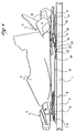
- FIG. 1 represents a partial view of a ski 1, taken in its middle zone of the skate.
- a ski boot has also been shown diagrammatically at 2, the front and rear ends of which are respectively retained on the ski 1 by a front binding element 3, and a rear binding element 4.
- the front fastening element 3 is of a known type, and it has in particular a base plate 5 which is assembled to the ski by any suitable means, and in particular by screws. These screws are not visible in FIG. 1, but their location has been shown diagrammatically by the dashed lines 6 and 7.
- the base plate 5 is extended towards the rear by a support plate 8 on which the front end rests. of the shoe sole.
- the rear fixing element 4 has, for its part, a base plate 9 along which the body 10 of the fixing element can slide.
- This base plate 9 is assembled to the ski by means which will be described later.
- the base plate 9 also has, in its front part, an extension 12 which serves to support the rear end of the shoe sole.
- the device according to the invention comprises a feeler which is in contact with the sole of the shoe, and which is movable in a vertical direction.
- the feeler is constituted by the extension 12 of the base plate 9. This extension supports the rear end of the shoe.
- the base plate 9 is connected to the ski 1 so that it can oscillate substantially in a vertical plane.
- a wedge 15 is interposed between the base plate 9 and the ski 1.
- the wedge 15 is assembled to the ski by any suitable means, and in particular by screwing.
- the base plate 9 is assembled to the ski 1 by means of the wedge 15.
- the assembly means comprise screws shown diagrammatically at 14 located in the rear part of the base plate 9.
- the holes in the base plate 9 through which the screws 14 pass are slightly ovalized in a longitudinal direction, so that the base plate 9 can oscillate around the screws 14 in the plane of FIG. 1. This oscillation movement exhibits a reduced amplitude, and Figure 1 shows the base plate 9 in its extreme high position.
- lateral tabs 16 secured to the wedge 15 guide the base plate 9 laterally.
- the tabs 16 also provide a vertical stop for the front part of the base plate 9.
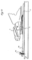
- the extension 12 of the base plate 9 can oscillate in an approximately vertical direction between the position which is represented in FIG. 1, and the position in which the base plate 9 is pressed against the shim 15. This position is shown in FIG. 2.
- a longitudinal retention of the base plate 9 is moreover carried out by any suitable means, and for example by lateral notches of the base plate 9 in which the cleats 16 are engaged.
- any suitable elastically compressible material and / or a spring may be interposed between the base plate 9 and the wedge 15, or the base plate 9 and the ski so as to elastically oppose a vertical downward movement of the extension 12.
- any other suitable means may be suitable provided that the probe, here constituted by the extension 12, is movable in an approximately vertical direction.
- the device according to the invention also has bending means for generating a bending moment on at least one end of the ski.
- the flexing means act on the front end of the ski. They consist of a base 17, the front end of which is interposed between the base plate 5 of the front binding element 3 and the upper surface of the ski. At this level, the base plate 5 and the front part of the base 17 are assembled in solidarity with the ski 1.
- the base 17 which is for example constituted by a rigid platform, extends towards the rear where it has a free end 18. At rest, the base 17 presses itself against the upper surface of the ski.
- the device according to the invention may also include connection means between the probe, constituted by the extension 12, and the free end 18 of the base 17.
- these means consist of a rocker 20 with two arms, one arm 21 being engaged under the probe, that is to say the front end of the extension 12, and the other arm 22 being engaged under the free end 18 of the base 17.
- the operation of the device according to the invention is as follows. In the normal position of the skier, illustrated in FIG. 1, the feeler 12 remains in the high position or close to this position, and the base 17 generates a zero or relatively low bending moment at the front end of the ski.
- FIG. 2 illustrates a position in rear support of the skier.
- the rear end of the shoe sole generates, on the feeler 12, an additional force which has been shown diagrammatically by the arrow 24.
- the feeler descends, which causes the rocker 20 to pivot. around its axis 23.
- This pivoting causes the free end 18 of the base 17 to be raised, which then generates an additional bending moment at the level of the base 5, which tends to cause the front end of the ski to sink.
- the device returns to the position illustrated in FIG. 1, and the additional bending moment on the front end of the ski disappears.
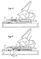
- FIG. 3 illustrates an alternative embodiment of the previous device.
- the base 17 extends forwardly beyond the base plate 5 of the front element 3.
- the base 17 thus has one end 25 offset forward.
- a screw 26, or any other suitable means provides a support connection between the base 17 and the upper surface of the ski.
- the screw 26 allows on the one hand to offset on the front of the ski the forces to which the ski is subjected on the part of the base 17.
- the screw 26 also makes it possible to adjust a bending preload of the front end of the ski.
- the front end 25 of the base 17 may have several orifices for receiving the screw 26 in different locations in a longitudinal direction, or else in a transverse direction.
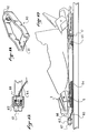
- FIG. 4 illustrates another implementation of the invention, mainly at the level of the bending means and the connecting means.
- the device shown in this figure comprises a base 27, the front part of which is interposed between the base plate 5 of the front element 3 and the upper surface of the ski.
- the base 27 In its rear part, the base 27 has a rim 30 which rises in a substantially vertical direction towards the sole of the shoe.
- connection means represented in FIG. 4, firstly comprise a small rocker 31, articulated around a transverse axis 32.
- One of the branches of the rocker 31 is engaged under the extension 12, and the other branch of the rocker is oriented so as to present at rest a substantially vertical bearing face 33, which extends under the hinge axis 32.
- a compression member 34 which is for example constituted by a bar or a compression blade. As shown in Figure 4, the compression member 34 is oblique.
- the operation of the device is as follows.
- a rear support of the shoe results in a downward movement of the extension 12, which causes a rotation of the rocker 31.
- the compression member 34 transmits this rotation to the rim 30 of the base 27 in the form of a stress in forward-facing compression. Since the fulcrum of the member 34 on the rim 30 is offset in height relative to the upper surface of the ski, this stress generates a bending moment on the front end of the ski, tending to cause this end down.
- the compression member is in two parts, a rear part 36 which extends along the upper surface of the ski, and which extends by a front portion 37 obliquely. As in the previous case, the front end of the part 37 bears against the rim 30 of the base 27.
- FIG. 6 represents another alternative embodiment, according to which the compression member 40 extends over its entire length along the upper surface of the ski.
- the rim 30 is extended towards the rear by a spoiler 41, and a rocker 42 articulated with an axis 43 connects the front end of the compression member 40 and the spoiler 41.
- the rocker 42 is of the same type as the rocker 31 previously described.
- Figure 7 shows an alternative embodiment.
- the extension 12 is connected to the rear end of the compression member 34 by a link 45.
- the link is mounted obliquely, its rear end is connected for example by articulation to the base plate 9 of the 'rear element 4. Its front end bears against the upper surface of the ski, or near the latter.
- a support of the shoe on the feeler 12 results in a downward movement of the extension 12, which causes the rotation of the link 45, and the displacement of its front end in an approximately longitudinal direction.
- FIG. 8 represents another variant according to which the preceding link 45 is replaced by a toggle device 47.
- the rear base plate 9 is supported, at the level of the feeler 12, on the central articulation of the two links 48 and 49 which constitute the toggle joint 47.
- a downward movement of the feeler 12 results in a crushing of the toggle joint 47, and a movement of the front end of the front link 48 in a longitudinal direction towards the front.
- FIG. 9 illustrates another implementation of the invention.
- the connection means comprise towards the rear a rocker 50 articulated around a transverse axis 51.
- the connection means comprise a rocker 52, articulated around a transverse axis 53.
- the two rockers 50 and 52 are connected by an inextensible link 54, for example a cable or a rod.
- the axes 51 and 53 are located in the lower part of the rockers 50 and 52 respectively so that a downward movement of the feeler 12 causes the rocker 50 to rotate, clockwise, which is transmitted by the inextensible link 54 to the rocker 52.
- the rocker 52 is rotated about its axis 53, and this rotation causes a vertical upward bias on the rear end of the base 57 located under the base plate 5 of the front element 3 .
- FIG. 10 represents an alternative embodiment of the device described with respect to FIG. 4.
- the bending means here consist of a stirrup 60, which is shown in FIG. 11.
- the stirrup 60 has a base 61 which is interposed between the bottom plate 5 of the front element 3 and the upper surface of the ski.
- the stirrup also has a central part 62 which is raised relative to the upper surface of the ski.
- the compression member is a compression blade 64, for example a blade of composite material, which can work on compression, and which moreover has flexural characteristics.
- the blade 64 is connected on the rear to a rocker 65 similar to the rocker 31 of FIG. 4. From this end, the blade 64 extends against the upper surface of the ski, passes under the base plate 5.
- the end before the blade 64 is offset upwards, and it is in abutment against a stop 66 which is integral with the central part 62 of the stirrup 60.
- the longitudinal position of the stop 66 can be adjusted by a threaded plug 67.
- This device is as follows. A thrust of the shoe on the feeler 12 results in a rotation of the rocker 65. This rotation causes a translation of the blade 64 in a longitudinal direction towards the front, hence a compression stress that the front end of the blade 64 exerts on the stop 66. This stress generates a bending moment at the level of the base plate 5 of the front element 3, which tends to cause the front end of the ski to sink down.
- rocker 65 can be replaced by other devices, for example those which have been described in FIGS. 7 and 8.
- FIG. 13 shows another alternative embodiment according to which the blade 64 is guided in the central part of its length under a cover 69.
- the rear end 68 of the blade which is located under the probe 12, is deformed upwards by buckling.
- a pressure of the shoe exerted on the feeler tends to absorb the buckling deformation of the end 68, which generates, as in the previous case, a translation of the blade 64 forwards.
- the probe 12 can be independent, that is to say dissociated from the base plate 9.
- the base plate would be integral with the ski, and the boot would rest on the feeler 12, with a possibility of urging the feeler downwards.
Landscapes
- Footwear And Its Accessory, Manufacturing Method And Apparatuses (AREA)
- Friction Gearing (AREA)
- Rolls And Other Rotary Bodies (AREA)
- Machine Tool Units (AREA)
Claims (11)
- Vorrichtung zum Ändern der Druckverteilung eines Ski, wie z. B. insbesondere einem Alpinski, auf dessen Gleitoberfläche, wobei der Ski mit Bindungselementen (3, 4) ausgerüstet ist, die dazu bestimmt sind, einen Schuh zu halten und mit zumindest einem Abstützelement (8, 12), auf dem die Sohle des Schuhes ruht,
dadurch gekennzeichnet, daß
er aufweist:- eine Fühlereinrichtung (12) in Kontakt mit der Sohle des Schuhes, die gemäß einer vertikalen Richtung beweglich ist;- eine Basis (17, 27, 57, 60), die dazu vorgesehen ist fest mit dem Ski verbunden zu sein und die in der Lage ist ein Durchbiegungsmoment auf einem vorderen oder hinteren Ende des Ski zu erzeugen;- eine Verbindung zur Kräfteübertragung (20, 34, 36, 40, 54, 64) zwischen der Fühlereinrichtung und der Basis, um zumindest einen Teil des vertikalen Druckes des Schuhes, der durch die Fühlereinrichtung erfaßt wird, auf die Basis zu übertragen. - Vorrichtung gemaß Anspruch 1, dadurch gekennzeichnet, daß die Basis (17, 27, 28, 57, 60) zwischen der Basisplatte (5) des Bindungselementes (3) und dem Ski zwischengelegt ist, und daß ein longitudinales Ende der Basis (18, 30, 62), das freies Ende genannt wird, durch die Verbindung zur Kräfteübertragung (20, 34, 36, 40, 54, 64) beansprucht ist.
- Vorrichtung gemäß Anspruch 2, dadurch gekennzeichnet, daß die Basis (17, 28, 57) sich in Richtung des anderen Bindungselementes verlängert, wo sie ein freies Ende (18, 41, 62) aufweist, und daß das freie Ende (18, 41, 62) vertikal nach oben durch die Verbindung zur Kräfteübertragung (20, 42, 53) beansprucht ist.
- Vorrichtung gemäß Anspruch 2, dadurch gekennzeichnet, daß ein Ende der Basis (27, 62) nach oben bezüglich der oberen Oberfläche des Ski versetzt ist, und daß das Ende (30, 62) in Druck durch die Verbindung zur Kräfteübertragung (34, 64) beansprucht ist.
- Vorrichtung gemäß Anspruch 1, dadurch gekennzeichnet, daß die Fühlereinrichtung (12) die Abstützungsoberfläche eines Endes des Schuhes bildet, wobei die Abstützungsoberfläche einem der Bindungselemente (4) zugeordnet ist.
- Vorrichtung gemäß Anspruch 5, dadurch gekennzeichnet, daß die Basisplatte (9) des Bindungselementes (4), das der Fühlereinrichtung zugeordnet ist, schwenkend in einer longitudinalen und vertikalen Ebene so montiert ist, daß die Abstützungsoberfläche (12) des Schuhes sich nach unten unter der Wirkung eines Stoßes des Schuhes absenken kann, der vertikal nach unten gerichtet ist.
- Vorrichtung gemaß Anspruch 3, dadurch gekennzeichnet, daß die Verbindung zur Kräfteübertragung eine Kippvorrichtung (20) mit zwei Armen aufweist, wobei ein Arm unter dem freien Ende (18) der Basis (17) in Eingriff ist.
- Vorrichtung gemäß Anspruch 4, dadurch gekennzeichnet, daß die Verbindung zur Kräfteübertragung eine Kompressionsvorrichtung (34, 36, 40, 64) aufweist, die in der Lage ist, eine Druckbeanspruchung auf die Basis (27, 28, 60) zu übertragen, die durch die vertikale Bewegung nach unten des Fühlers (12) erzeugt ist.
- Vorrichtung gemäß Anspruch 4, dadurch gekennzeichnet, daß die Verbindung zur Kräfteübertragung eine nicht ausdehnbare Einrichtung (54) aufweist, die in der Lage ist eine Zugbeanspruchung auf die Basis (57) zu übertragen, die durch die vertikale Bewegung nach unten des Fühlers (12) erzeugt ist.
- Vorrichtung gemäß Anspruch 2, dadurch gekennzeichnet, daß auf der ihrem freien Ende gegenüberliegenden Seite (25) die Basis sich über das Bindungselement (3) hinaus verlängert, der es zugeordnet ist, und daß sie über die Basisplatte hinaus einen Abstützungspunkt (26) gegen die obere Oberfläche des Ski aufweist.
- Ski, insbesondere Alpinski, dadurch gekennzeichnet, daß er eine Vorrichtung gemäß irgendeinem der vorhergenden Ansprüche aufweist.
Applications Claiming Priority (2)
| Application Number | Priority Date | Filing Date | Title |
|---|---|---|---|
| FR9110895 | 1991-08-27 | ||
| FR9110895A FR2680697B1 (fr) | 1991-08-27 | 1991-08-27 | Dispositif visant a modifier la repartition de pression d'un ski sur la surface de glisse. |
Publications (2)
| Publication Number | Publication Date |
|---|---|
| EP0530449A1 EP0530449A1 (de) | 1993-03-10 |
| EP0530449B1 true EP0530449B1 (de) | 1995-06-21 |
Family
ID=9416593
Family Applications (1)
| Application Number | Title | Priority Date | Filing Date |
|---|---|---|---|
| EP92109438A Expired - Lifetime EP0530449B1 (de) | 1991-08-27 | 1992-06-04 | Vorrichtung zur Änderung der Druckverteilung eines Skis auf seiner Gleitfläche |
Country Status (6)
| Country | Link |
|---|---|
| US (1) | US5332253A (de) |
| EP (1) | EP0530449B1 (de) |
| JP (1) | JPH05220246A (de) |
| AT (1) | ATE123960T1 (de) |
| DE (1) | DE69203053T2 (de) |
| FR (1) | FR2680697B1 (de) |
Families Citing this family (25)
| Publication number | Priority date | Publication date | Assignee | Title |
|---|---|---|---|---|
| US5513872A (en) * | 1991-08-27 | 1996-05-07 | Salomon S.A. | Interface device to modify the natural pressure distribution of a ski on the snow |
| US5566966A (en) * | 1991-08-27 | 1996-10-22 | Salomon S.A. | Device for modifying the pressure distribution of a ski along its sliding surface |
| FR2684885B1 (fr) * | 1991-12-11 | 1994-02-04 | Salomon Sa | Dispositif visant a repartir la pression d'un ski sur une surface de glisse. |
| FR2686799B1 (fr) * | 1992-01-31 | 1994-03-25 | Salomon Sa | Dispositif visant a modifier la repartition d'un ski sur sa surface de glisse et ski equipe d'un tel dispositif. |
| FR2686798B1 (fr) * | 1992-01-31 | 1994-03-25 | Salomon Sa | Dispositif visant a modifier la repartition d'un ski sur sa surface de glisse et ski equipe d'un tel dispositif. |
| US5642897A (en) * | 1992-02-18 | 1997-07-01 | Salomon S.A. | Ski brake and device for modifying the natural pressure distribution of a ski over its sliding surface and a ski equipped therewith |
| FR2707511B1 (fr) * | 1993-07-16 | 1995-12-08 | Salomon Sa | Dispositif visant à modifier la répartition naturelle d'un ski sur sa surface de glisse, et ski équipé d'un tel dispositif. |
| FR2709974B1 (fr) * | 1993-09-17 | 1995-10-20 | Rossignol Sa | Dispositif de montage d'une chaussure sur un ski alpin. |
| FR2711321B1 (fr) * | 1993-10-20 | 1995-12-08 | Salomon Sa | Ski muni d'un dispositif destiné à diminuer la pression des extrémités du ski sur la neige suivant l'appui du skieur sur le ski. |
| FR2713945B1 (fr) * | 1993-12-17 | 1996-03-29 | Salomon Sa | Dispositif interface entre un ski et des éléments de fixation. |
| FR2718046B1 (fr) * | 1994-04-05 | 1996-05-31 | Salomon Sa | Dispositif interface entre une chaussure et un ski. |
| FR2719781B1 (fr) * | 1994-05-16 | 1996-07-12 | Salomon Sa | Dispositif interface visant à modifier la répartition naturelle de pression d'un ski tel que notamment un ski alpin. |
| DE29521349U1 (de) * | 1994-05-21 | 1997-02-06 | Götzfried, Peter, 87527 Sonthofen | Vorrichtung zum gezielten Beeinflussen der Längswölbung eines Alpinskis |
| US5590908A (en) * | 1995-07-07 | 1997-01-07 | Carr; Donald W. | Sports board having a pressure sensitive panel responsive to contact between the sports board and a surface being ridden |
| US5775715A (en) * | 1995-08-01 | 1998-07-07 | K-2 Corporation | Piezoelectric damper for a board such as a snow ski or snowboard |
| US6095547A (en) * | 1995-08-01 | 2000-08-01 | K-2 Corporation | Active piezoelectric damper for a snow ski or snowboard |
| FR2738157B1 (fr) * | 1995-09-06 | 1997-10-17 | Salomon Sa | Dispositif de fixation automatique |
| US20020024187A1 (en) * | 1995-10-02 | 2002-02-28 | Kaj Gyr | Snowboard suspension system |
| FR2770413B1 (fr) | 1997-11-03 | 2000-02-11 | Salomon Sa | Element de retenue de l'arriere d'une chaussure sur un engin de glisse du type ski |
| EP1031360A1 (de) * | 1999-02-24 | 2000-08-30 | Roland Bünter | Skiführungsdruckverstärker-Platte (Snow-Speed) |
| SI22740A (sl) * | 2008-03-31 | 2009-10-31 | Alu-B D.O.O. | Platforma za pritrditev smučarske vezi na smučko |
| AT506545B1 (de) * | 2008-04-02 | 2012-05-15 | Atomic Austria Gmbh | Brettartiges gleitgerät mit einer einstellvorrichtung zur veränderung des nutzungsverhaltens |
| FR2965187B1 (fr) * | 2010-09-28 | 2012-10-26 | Rossignol Sa | Dispositif de fixation de chaussure sur un ski avec interface de securite |
| USD820932S1 (en) * | 2016-05-04 | 2018-06-19 | Salomon S.A.S. | Ski binding |
| USD820933S1 (en) * | 2016-05-04 | 2018-06-19 | Salomon S.A.S. | Ski binding |
Family Cites Families (11)
| Publication number | Priority date | Publication date | Assignee | Title |
|---|---|---|---|---|
| US2258046A (en) * | 1940-05-24 | 1941-10-07 | Clement Manufacture Enregistre | Ski |
| FR1109560A (fr) * | 1954-07-31 | 1956-01-31 | Perfectionnements aux skis | |
| US3260532A (en) * | 1965-04-02 | 1966-07-12 | Johan G F Heuvel | Ski binding mounting and runner construction |
| FR1433242A (fr) * | 1965-05-14 | 1966-03-25 | Dispositif de compression, notamment pour ski et skis munis dudit dispositif | |
| DE2634748A1 (de) * | 1976-01-20 | 1978-02-09 | Hans Meyer | Ski mit federbrett |
| FR2448360A1 (fr) * | 1979-02-08 | 1980-09-05 | Savoie Rene | Dispositif pour regler sur place les caracteristiques d'un ski |
| SE436690B (sv) * | 1983-05-20 | 1985-01-21 | Eriksson Karl G V | Anordning vid skida med variabelt spann |
| FR2572296A1 (fr) * | 1984-10-31 | 1986-05-02 | Jacques Alain | Dispositif de fixation intermediaire de chaussures sur un ski |
| AT385667B (de) * | 1984-11-15 | 1988-05-10 | Head Sportgeraete Gmbh | Ski fuer die verwendung mit einer auflageplatte fuer die aufnahme von bindungsteilen |
| DE3628476C2 (de) * | 1986-08-22 | 1995-11-02 | Head Sport Ag | Ski mit Härteausgleichselementen und Härteregulierungselementen |
| FR2649902B1 (fr) * | 1989-07-18 | 1992-07-03 | Rossignol Sa | Dispositif complementaire au ski permettant le montage d'un jeu de fixations d'une chaussure sur un ski |
-
1991
- 1991-08-27 FR FR9110895A patent/FR2680697B1/fr not_active Expired - Fee Related
-
1992
- 1992-06-04 EP EP92109438A patent/EP0530449B1/de not_active Expired - Lifetime
- 1992-06-04 DE DE69203053T patent/DE69203053T2/de not_active Expired - Fee Related
- 1992-06-04 AT AT92109438T patent/ATE123960T1/de not_active IP Right Cessation
- 1992-07-10 US US07/911,702 patent/US5332253A/en not_active Expired - Fee Related
- 1992-08-24 JP JP4223688A patent/JPH05220246A/ja not_active Withdrawn
Also Published As
| Publication number | Publication date |
|---|---|
| ATE123960T1 (de) | 1995-07-15 |
| JPH05220246A (ja) | 1993-08-31 |
| DE69203053D1 (de) | 1995-07-27 |
| FR2680697B1 (fr) | 1993-11-05 |
| DE69203053T2 (de) | 1995-11-16 |
| FR2680697A1 (fr) | 1993-03-05 |
| EP0530449A1 (de) | 1993-03-10 |
| US5332253A (en) | 1994-07-26 |
Similar Documents
| Publication | Publication Date | Title |
|---|---|---|
| EP0530449B1 (de) | Vorrichtung zur Änderung der Druckverteilung eines Skis auf seiner Gleitfläche | |
| EP0556610B1 (de) | Vorrichtung zum Verändern der natürlichen Druckverteilung eines Skis auf seine Gleitfläche | |
| EP0617638B1 (de) | Einrichtung zur druckverteilung eines schis auf der gleitläche | |
| EP0624113B1 (de) | Vorrichtung zum verändern der natürlichen druckverteilung eines skis auf einer gleitfläche | |
| EP0567780B1 (de) | Ski mit Auflageplatte | |
| EP0685244A1 (de) | Auflageplatte zwischen Ski und Bindung, insbesondere Alpinski | |
| EP0692288B1 (de) | Bindung für Alpinski | |
| FR2687326A1 (fr) | Dispositif visant a modifier la repartition naturelle d'un ski sur sa surface de glisse, et ski equipe d'un tel dispositif. | |
| EP0653231B1 (de) | Bindungselement für Skier | |
| EP0674925B1 (de) | Skibindung | |
| EP0641233B1 (de) | Vorrichtung zum verändern der natürlichen druckverteilung eines skis auf seinegleitfläche | |
| EP0634196B1 (de) | Bindungselement für einen alphinen Ski | |
| EP0599041B1 (de) | Trägerplatte zwischen Ski und Bindung | |
| EP0660740B1 (de) | Vorrichtung zum verteilen des drucks eines skis auf einer gleitenden fläche | |
| EP0623370A1 (de) | Trägerplatte zwischen Ski und Bindung | |
| EP0667174B1 (de) | Sicherheitsbindung für Skier mit Ausgleichsvorrichtung | |
| FR2679147A1 (fr) | Dispositif visant a modifier la repartition de pression d'un ski sur sa surface de glisse. | |
| FR2690079A1 (fr) | Dispositif interface destiné à modifier la répartition naturelle de pression d'un ski sur sa surface de glisse. | |
| EP0672437B1 (de) | Vorrichtung zum Veränderen der natürlichen Druckverteilung eines Skis aus Schnee | |
| FR2657269A1 (fr) | Fixation de securite de ski alpin. | |
| FR2693659A1 (fr) | Dispositif interface destiné à modifier à la répartition naturelle de pression d'un ski sur sa surface de glisse. | |
| FR2774603A1 (fr) | Element de retenue de l'avant d'une chaussure sur un ski |
Legal Events
| Date | Code | Title | Description |
|---|---|---|---|
| PUAI | Public reference made under article 153(3) epc to a published international application that has entered the european phase |
Free format text: ORIGINAL CODE: 0009012 |
|
| AK | Designated contracting states |
Kind code of ref document: A1 Designated state(s): AT CH DE IT LI |
|
| 17P | Request for examination filed |
Effective date: 19930325 |
|
| 17Q | First examination report despatched |
Effective date: 19940301 |
|
| GRAA | (expected) grant |
Free format text: ORIGINAL CODE: 0009210 |
|
| AK | Designated contracting states |
Kind code of ref document: B1 Designated state(s): AT CH DE IT LI |
|
| REF | Corresponds to: |
Ref document number: 123960 Country of ref document: AT Date of ref document: 19950715 Kind code of ref document: T |
|
| REF | Corresponds to: |
Ref document number: 69203053 Country of ref document: DE Date of ref document: 19950727 |
|
| ITF | It: translation for a ep patent filed | ||
| PLBE | No opposition filed within time limit |
Free format text: ORIGINAL CODE: 0009261 |
|
| STAA | Information on the status of an ep patent application or granted ep patent |
Free format text: STATUS: NO OPPOSITION FILED WITHIN TIME LIMIT |
|
| 26N | No opposition filed | ||
| PGFP | Annual fee paid to national office [announced via postgrant information from national office to epo] |
Ref country code: CH Payment date: 19970926 Year of fee payment: 6 |
|
| PG25 | Lapsed in a contracting state [announced via postgrant information from national office to epo] |
Ref country code: LI Free format text: LAPSE BECAUSE OF NON-PAYMENT OF DUE FEES Effective date: 19980630 Ref country code: CH Free format text: LAPSE BECAUSE OF NON-PAYMENT OF DUE FEES Effective date: 19980630 |
|
| REG | Reference to a national code |
Ref country code: CH Ref legal event code: PL |
|
| PGFP | Annual fee paid to national office [announced via postgrant information from national office to epo] |
Ref country code: AT Payment date: 20000619 Year of fee payment: 9 |
|
| PGFP | Annual fee paid to national office [announced via postgrant information from national office to epo] |
Ref country code: DE Payment date: 20000726 Year of fee payment: 9 |
|
| PG25 | Lapsed in a contracting state [announced via postgrant information from national office to epo] |
Ref country code: AT Free format text: LAPSE BECAUSE OF NON-PAYMENT OF DUE FEES Effective date: 20010604 |
|
| PG25 | Lapsed in a contracting state [announced via postgrant information from national office to epo] |
Ref country code: DE Free format text: LAPSE BECAUSE OF NON-PAYMENT OF DUE FEES Effective date: 20020403 |
|
| PG25 | Lapsed in a contracting state [announced via postgrant information from national office to epo] |
Ref country code: IT Free format text: LAPSE BECAUSE OF NON-PAYMENT OF DUE FEES Effective date: 20050604 |