EP0807398B1 - Dishwasher - Google Patents
Dishwasher Download PDFInfo
- Publication number
- EP0807398B1 EP0807398B1 EP97111849A EP97111849A EP0807398B1 EP 0807398 B1 EP0807398 B1 EP 0807398B1 EP 97111849 A EP97111849 A EP 97111849A EP 97111849 A EP97111849 A EP 97111849A EP 0807398 B1 EP0807398 B1 EP 0807398B1
- Authority
- EP
- European Patent Office
- Prior art keywords
- wash
- chamber
- cabinet
- pump
- wash chamber
- Prior art date
- Legal status (The legal status is an assumption and is not a legal conclusion. Google has not performed a legal analysis and makes no representation as to the accuracy of the status listed.)
- Expired - Lifetime
Links
- 239000007921 spray Substances 0.000 claims abstract description 54
- 239000007788 liquid Substances 0.000 claims abstract description 51
- XLYOFNOQVPJJNP-UHFFFAOYSA-N water Substances O XLYOFNOQVPJJNP-UHFFFAOYSA-N 0.000 claims description 75
- 238000006073 displacement reaction Methods 0.000 claims description 4
- 230000009977 dual effect Effects 0.000 claims description 3
- 230000006698 induction Effects 0.000 claims description 3
- 230000000295 complement effect Effects 0.000 claims 1
- 238000005406 washing Methods 0.000 description 30
- 238000010438 heat treatment Methods 0.000 description 15
- 238000004804 winding Methods 0.000 description 13
- 230000001360 synchronised effect Effects 0.000 description 11
- 230000008901 benefit Effects 0.000 description 10
- 238000000034 method Methods 0.000 description 9
- 239000002184 metal Substances 0.000 description 8
- 229910052751 metal Inorganic materials 0.000 description 8
- 239000004033 plastic Substances 0.000 description 7
- 229920003023 plastic Polymers 0.000 description 7
- 235000014676 Phragmites communis Nutrition 0.000 description 6
- 238000010276 construction Methods 0.000 description 6
- 238000004140 cleaning Methods 0.000 description 5
- 238000001035 drying Methods 0.000 description 5
- 238000009434 installation Methods 0.000 description 5
- 230000007246 mechanism Effects 0.000 description 5
- 230000002829 reductive effect Effects 0.000 description 5
- 230000002441 reversible effect Effects 0.000 description 5
- 239000003599 detergent Substances 0.000 description 4
- 238000010586 diagram Methods 0.000 description 4
- 239000000463 material Substances 0.000 description 4
- 238000009428 plumbing Methods 0.000 description 4
- 230000037452 priming Effects 0.000 description 4
- 238000005086 pumping Methods 0.000 description 4
- XEEYBQQBJWHFJM-UHFFFAOYSA-N Iron Chemical compound [Fe] XEEYBQQBJWHFJM-UHFFFAOYSA-N 0.000 description 3
- 230000015572 biosynthetic process Effects 0.000 description 3
- 238000006243 chemical reaction Methods 0.000 description 3
- 230000008878 coupling Effects 0.000 description 3
- 238000010168 coupling process Methods 0.000 description 3
- 238000005859 coupling reaction Methods 0.000 description 3
- 238000005516 engineering process Methods 0.000 description 3
- 239000012530 fluid Substances 0.000 description 3
- 239000000411 inducer Substances 0.000 description 3
- 238000003475 lamination Methods 0.000 description 3
- 238000004519 manufacturing process Methods 0.000 description 3
- 238000000465 moulding Methods 0.000 description 3
- 238000005507 spraying Methods 0.000 description 3
- 229910000831 Steel Inorganic materials 0.000 description 2
- 230000009471 action Effects 0.000 description 2
- 239000003990 capacitor Substances 0.000 description 2
- 230000008859 change Effects 0.000 description 2
- 238000001816 cooling Methods 0.000 description 2
- 230000003247 decreasing effect Effects 0.000 description 2
- 238000013461 design Methods 0.000 description 2
- 230000000694 effects Effects 0.000 description 2
- 238000012544 monitoring process Methods 0.000 description 2
- 230000036961 partial effect Effects 0.000 description 2
- 239000002689 soil Substances 0.000 description 2
- 239000010959 steel Substances 0.000 description 2
- 239000000758 substrate Substances 0.000 description 2
- 238000012546 transfer Methods 0.000 description 2
- 230000005355 Hall effect Effects 0.000 description 1
- 239000004743 Polypropylene Substances 0.000 description 1
- 238000005299 abrasion Methods 0.000 description 1
- 230000004913 activation Effects 0.000 description 1
- 230000006978 adaptation Effects 0.000 description 1
- 238000005452 bending Methods 0.000 description 1
- 230000009286 beneficial effect Effects 0.000 description 1
- 230000000740 bleeding effect Effects 0.000 description 1
- 239000000872 buffer Substances 0.000 description 1
- 238000004364 calculation method Methods 0.000 description 1
- 239000002131 composite material Substances 0.000 description 1
- 238000011109 contamination Methods 0.000 description 1
- 230000001276 controlling effect Effects 0.000 description 1
- 238000010411 cooking Methods 0.000 description 1
- 210000003298 dental enamel Anatomy 0.000 description 1
- 238000001514 detection method Methods 0.000 description 1
- 238000005265 energy consumption Methods 0.000 description 1
- 230000004907 flux Effects 0.000 description 1
- 238000005187 foaming Methods 0.000 description 1
- 239000011521 glass Substances 0.000 description 1
- 229910052742 iron Inorganic materials 0.000 description 1
- 238000010030 laminating Methods 0.000 description 1
- 230000000670 limiting effect Effects 0.000 description 1
- 238000012423 maintenance Methods 0.000 description 1
- 230000007257 malfunction Effects 0.000 description 1
- 238000007726 management method Methods 0.000 description 1
- 239000000203 mixture Substances 0.000 description 1
- 239000002991 molded plastic Substances 0.000 description 1
- 230000003287 optical effect Effects 0.000 description 1
- 235000012771 pancakes Nutrition 0.000 description 1
- 239000002245 particle Substances 0.000 description 1
- 238000005192 partition Methods 0.000 description 1
- -1 polypropylene Polymers 0.000 description 1
- 229920001155 polypropylene Polymers 0.000 description 1
- 229910052573 porcelain Inorganic materials 0.000 description 1
- 230000001737 promoting effect Effects 0.000 description 1
- 230000001105 regulatory effect Effects 0.000 description 1
- 230000000717 retained effect Effects 0.000 description 1
- 239000004065 semiconductor Substances 0.000 description 1
- 230000035939 shock Effects 0.000 description 1
- 239000007787 solid Substances 0.000 description 1
- 230000003068 static effect Effects 0.000 description 1
- 238000003860 storage Methods 0.000 description 1
- 230000003685 thermal hair damage Effects 0.000 description 1
- 230000001960 triggered effect Effects 0.000 description 1
- 239000002699 waste material Substances 0.000 description 1
- 229910000859 α-Fe Inorganic materials 0.000 description 1
Images


Classifications
-
- A—HUMAN NECESSITIES
- A47—FURNITURE; DOMESTIC ARTICLES OR APPLIANCES; COFFEE MILLS; SPICE MILLS; SUCTION CLEANERS IN GENERAL
- A47L—DOMESTIC WASHING OR CLEANING; SUCTION CLEANERS IN GENERAL
- A47L15/00—Washing or rinsing machines for crockery or tableware
-
- A—HUMAN NECESSITIES
- A47—FURNITURE; DOMESTIC ARTICLES OR APPLIANCES; COFFEE MILLS; SPICE MILLS; SUCTION CLEANERS IN GENERAL
- A47L—DOMESTIC WASHING OR CLEANING; SUCTION CLEANERS IN GENERAL
- A47L15/00—Washing or rinsing machines for crockery or tableware
- A47L15/14—Washing or rinsing machines for crockery or tableware with stationary crockery baskets and spraying devices within the cleaning chamber
- A47L15/18—Washing or rinsing machines for crockery or tableware with stationary crockery baskets and spraying devices within the cleaning chamber with movably-mounted spraying devices
- A47L15/22—Rotary spraying devices
- A47L15/23—Rotary spraying devices moved by means of the sprays
-
- A—HUMAN NECESSITIES
- A47—FURNITURE; DOMESTIC ARTICLES OR APPLIANCES; COFFEE MILLS; SPICE MILLS; SUCTION CLEANERS IN GENERAL
- A47L—DOMESTIC WASHING OR CLEANING; SUCTION CLEANERS IN GENERAL
- A47L15/00—Washing or rinsing machines for crockery or tableware
- A47L15/0084—Washing or rinsing machines for crockery or tableware of drawer-type
-
- A—HUMAN NECESSITIES
- A47—FURNITURE; DOMESTIC ARTICLES OR APPLIANCES; COFFEE MILLS; SPICE MILLS; SUCTION CLEANERS IN GENERAL
- A47L—DOMESTIC WASHING OR CLEANING; SUCTION CLEANERS IN GENERAL
- A47L15/00—Washing or rinsing machines for crockery or tableware
- A47L15/0089—Washing or rinsing machines for crockery or tableware of small size, e.g. portable mini dishwashers for small kitchens, office kitchens, boats, recreational vehicles
-
- A—HUMAN NECESSITIES
- A47—FURNITURE; DOMESTIC ARTICLES OR APPLIANCES; COFFEE MILLS; SPICE MILLS; SUCTION CLEANERS IN GENERAL
- A47L—DOMESTIC WASHING OR CLEANING; SUCTION CLEANERS IN GENERAL
- A47L15/00—Washing or rinsing machines for crockery or tableware
- A47L15/42—Details
- A47L15/4202—Water filter means or strainers
- A47L15/4204—Flat filters
-
- A—HUMAN NECESSITIES
- A47—FURNITURE; DOMESTIC ARTICLES OR APPLIANCES; COFFEE MILLS; SPICE MILLS; SUCTION CLEANERS IN GENERAL
- A47L—DOMESTIC WASHING OR CLEANING; SUCTION CLEANERS IN GENERAL
- A47L15/00—Washing or rinsing machines for crockery or tableware
- A47L15/42—Details
- A47L15/4214—Water supply, recirculation or discharge arrangements; Devices therefor
- A47L15/4217—Fittings for water supply, e.g. valves or plumbing means to connect to cold or warm water lines, aquastops
-
- A—HUMAN NECESSITIES
- A47—FURNITURE; DOMESTIC ARTICLES OR APPLIANCES; COFFEE MILLS; SPICE MILLS; SUCTION CLEANERS IN GENERAL
- A47L—DOMESTIC WASHING OR CLEANING; SUCTION CLEANERS IN GENERAL
- A47L15/00—Washing or rinsing machines for crockery or tableware
- A47L15/42—Details
- A47L15/4214—Water supply, recirculation or discharge arrangements; Devices therefor
- A47L15/4219—Water recirculation
- A47L15/4221—Arrangements for redirection of washing water, e.g. water diverters to selectively supply the spray arms
-
- A—HUMAN NECESSITIES
- A47—FURNITURE; DOMESTIC ARTICLES OR APPLIANCES; COFFEE MILLS; SPICE MILLS; SUCTION CLEANERS IN GENERAL
- A47L—DOMESTIC WASHING OR CLEANING; SUCTION CLEANERS IN GENERAL
- A47L15/00—Washing or rinsing machines for crockery or tableware
- A47L15/42—Details
- A47L15/4214—Water supply, recirculation or discharge arrangements; Devices therefor
- A47L15/4225—Arrangements or adaption of recirculation or discharge pumps
-
- A—HUMAN NECESSITIES
- A47—FURNITURE; DOMESTIC ARTICLES OR APPLIANCES; COFFEE MILLS; SPICE MILLS; SUCTION CLEANERS IN GENERAL
- A47L—DOMESTIC WASHING OR CLEANING; SUCTION CLEANERS IN GENERAL
- A47L15/00—Washing or rinsing machines for crockery or tableware
- A47L15/42—Details
- A47L15/4246—Details of the tub
-
- A—HUMAN NECESSITIES
- A47—FURNITURE; DOMESTIC ARTICLES OR APPLIANCES; COFFEE MILLS; SPICE MILLS; SUCTION CLEANERS IN GENERAL
- A47L—DOMESTIC WASHING OR CLEANING; SUCTION CLEANERS IN GENERAL
- A47L15/00—Washing or rinsing machines for crockery or tableware
- A47L15/42—Details
- A47L15/4251—Details of the casing
-
- A—HUMAN NECESSITIES
- A47—FURNITURE; DOMESTIC ARTICLES OR APPLIANCES; COFFEE MILLS; SPICE MILLS; SUCTION CLEANERS IN GENERAL
- A47L—DOMESTIC WASHING OR CLEANING; SUCTION CLEANERS IN GENERAL
- A47L15/00—Washing or rinsing machines for crockery or tableware
- A47L15/42—Details
- A47L15/4285—Water-heater arrangements
-
- H—ELECTRICITY
- H02—GENERATION; CONVERSION OR DISTRIBUTION OF ELECTRIC POWER
- H02P—CONTROL OR REGULATION OF ELECTRIC MOTORS, ELECTRIC GENERATORS OR DYNAMO-ELECTRIC CONVERTERS; CONTROLLING TRANSFORMERS, REACTORS OR CHOKE COILS
- H02P6/00—Arrangements for controlling synchronous motors or other dynamo-electric motors using electronic commutation dependent on the rotor position; Electronic commutators therefor
- H02P6/26—Arrangements for controlling single phase motors
Definitions
- This invention relates to dishwashers, and in particular, but not solely, domestic dishwashers.
- Conventional domestic front loading dishwashers provide two racks for stacking dishes, one in the lower zone of the wash chamber and the other in the upper zone.
- Such dishwashers are normally designed to fit under a typical domestic kitchen bench top with a maximum height of 900mm.
- the lower rack is designed to take larger dishes, e.g. plates up to 280mm in diameter, and because of the overall height limitation the upper rack can only take lower height dishes.
- Such dishwashers lack flexibility in that they cannot efficiently wash (in a single wash) dish loads made up of a mix of dish sizes other than that dictated by the manufacturer. For example, a load of large diameter plates exceeding the number that can be accommodated in the lower rack must be cleaned using two completely separate wash cycles, even although the top rack could be empty. Further, it is not feasible to load soiled dishes unless all cleaned dishes are first removed. In addition it is not efficient to wash less than full loads. Washing must be deferred until the dishwasher has been completely filled.
- the first two problems identified above can be overcome to some extent by the use of two dishwashers. However, cost and space factors usually mean this is not a viable option.
- the present invention proposes a solution to the above problems by providing a smaller dishwasher intended to be used as one module in a two-module pair.
- the dishwasher is of very low height to allow the option of "over and under" stacking of two modules below a kitchen bench.
- access is provided by constructing the dishwasher with a sliding wash chamber which may be withdrawn from its cabinet in the manner of a file drawer.
- US 2668091 discloses a sliding wash chamber, although not for the purpose of fitting two such dishwashers one above the other under a domestic kitchen bench.
- US 2668091 also discloses a lid to seal the open top of the wash chamber during the washing process which is supported under the roof of the dishwasher cabinet by links which allow the lid to be moved in a parallelogram motion to close onto the wash chamber as it is fully retracted into the cabinet.
- wash and drain pumps driven by a common induction motor are disclosed which are located inside the wash chamber and the motor is operable submerged in the wash water.
- a disadvantage of this system is the need to seal the motor stator from the wash liquid.
- a drain pump which operates with a submerged motor rotor and a stator external to the pump casing is disclosed in EP 287,984 (Askoll SPA).
- this pump requires the use of two separate chambers for the motor rotor and pump impeller respectively and is not easy to service in use. Further, it is not possible to use the motor disclosed to additionally drive a wash pump.
- EP 76,739 (Esswein), EP 268,835 (Industrie Zanussi) and US 3,810,480 (Smith and Faust) disclose other constructions where the wash and drain pumps are driven by a common motor where the direction of rotation of the motor determines which pump is operable. These constructions do not significantly reduce the height requirements of the wash system.
- a small top loading dishwasher (“Bauknecht”) for mounting within a kitchen cupboard and able to be extended from the cupboard on slides has been manufactured by Philips Appliances, but this does not address the problems outlined above, and in particular requires users to lift the wash chamber lid after cupboard opening and complete withdrawal of the machine from the cupboard.
- the invention consists in a dishwasher comprising:
- the dishwasher is constructed with a height dimension approximately half that of conventional front-loading domestic dishwashers. It is intended to be used alone or as one of a number, more usually one of a pair of such dishwashers.
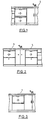
- FIG. 1 various installation concepts using one or two dishwashers according to the present invention are shown. It is a concept of the present invention to provide a modular dishwasher unit.
- two such dishwashers 2 are shown stacked one above the other under a sink bench 1 which will typically be between 850 and 900mm above floor level.
- two dishwashers 2 are shown mounted one on either side of a sink forming part of the sink bench 1.
- Figure 3 only a single dishwasher 2 is provided under a sink bench 1. Because of the reduced height dimension a dishwasher according to the invention could be bench mounted.
- each dishwasher 2 can be regarded as a modular unit which is an independent self contained dishwasher capable of accommodating any conventional dish load.
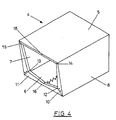
- the present dishwasher cabinet is constructed from sheet metal to form a five sited box structure having a top 5 a bottom 6 and sides 7 and 8 and back (not shown).
- the open front of the cabinet 4 is flanged as a portal frame having two portal members 10 and 11, these portal members decreasing in depth from the comers 12 and 13 to the extremities 14 and 15 and decreasing along the bottom face to a central joint 16.
- This technique enables an adequate sized opening to be provided in the cabinet while at the same time provides adequate stiffness to the front of the cabinet.
- This technique overcomes the rigidity problem presented by any open sided box structure and could be used in many applications beside dishwasher cabinets.
- the portal frame members 11 and 12 are jointed together at 16 by a very thin section of metal which in structural terms comprises essential a pin joint. Similarly, ends 14 and 15 of the portal members are effectively joined to flange section 18 by pin joints. This section effectively forms a beam to tie together the ends of the portal members. Unlike the conventional application for portal frames joint 16 is not subject to any significant load normal to panel 6. The function of the portal frame in the present application is to provide bracing against transverse loads and there is no requirement or advantage in having joint 16 moment resisting.
- the portal could be inverted but the orientation shown assists in allowing clearance for a drain pump to be described later. It also means the portal frame profile substantially follows the profile of the wash chamber which itself is shaped so as to optimally hold large plates.
- One aspect of the present invention is that a dishwasher is provided whereby the wash chamber in which dishes are placed, together with all other components necessary to the wash system, is mounted within a cabinet on slides to function as a drawer.
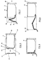
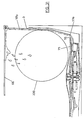
- This configuration is shown in Figure 5 where a wash chamber 3 is shown slidably mounted within cabinet 4 in a partially withdrawn position.
- facia 20 is fitted to the front of wash chamber 3 and incorporates a drawer pull (not shown). When fully retracted or dosed (as shown in Figure 6) facia 20 abuts the front of the cabinet 3.
- a dishwasher as described is intended for installation in an open cavity, usually under a bench, so that the facia 20 effectively doses off the cavity and is the visible component of the dishwasher in the same manner as with conventional front loading dishwashers
- drawer configuration means that flexible and extending cable and hose arrangements are required for running between the cabinet and the wash system. Electrical connections for the drawer mounted components could be provided by a socket 31 attached to the cabinet and a plug 32 attached to the washing chamber. Connection is made when the drawer 17 is in the substantially fully home position. Preferably, however, fixed wiring is employed using a flexible cable loop. In this form the electrical cable could be attached compositely to the drain hose shown in Figures 6 to 8.
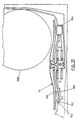
- a drain hose 35 ( Figures 6 to 8) is formed in a loop and is arranged to have a central portion 36 transverse to the direction of movement of the chamber with two arms 37 and 38 connected to the central portion.
- the drain hose arms 37 and 38 bend where they are connected to central portion 36 so that the two arms move from a position in substantially the same plane (orthogonal angles to the direction of movement of the drawer 17) as shown in Figure 6 to the position shown in Figure 8 where the two arms are more or less in the same plane but at right angles to the position shown in Figure 6.
- This arrangement minimises the space required to accommodate the drainage hose when the wash chamber is in the dosed position.
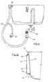
- a wash hose 40 connects between a discharge spout 53 and an electrically operated water valve 51.
- Valve 51 could be a solenoid valve, for example.
- Valve 51 is in use coupled to a household wash supply tap 46.
- the valve 51 is moulded to the hose 40.
- an electrical cable is also moulded to hose 40 to provide an electrical connection to valve 41.
- the electrical connector 47 is attached to a cable tail 47 allowing connection to the dishwasher controller through a cabinet mounted socket.
- Wash water is supplied to a reservoir tank 33 which is partially integrally formed with the wash chamber 3 (see Figure 10).
- the chamber 3 has a dosed flange on one end wash.
- a moulded plastics cover member 44 is welded to the flange dry line for form the tank 33.
- the tank 33 shares a common wall 34 with the wash chamber. The use of a separate tank of much smaller horizontal cross section than that of the wash chamber 3 allows accurate metering of the volume of water used for washing. This is especially important where, as here, a relatively small change of water is used - typically 2 litres.
- the water supply hose 40 is shown connected to electrically actuated inlet valve 51 fed from a supply of cold water.
- the water supply hose terminates at a spout 53 fixed to the cabinet 4.
- Spout 53 discharges into tank 33 only when wash chamber 3 is in the dosed position.
- a flexible hose 52 ( Figure 18) may be connected from the cabinet 4 to a spout 54 fixed to the tank 33. in either case inlet valve 51 cannot be opened unless the wash chamber 3 is in the dosed position.
- An interlock switch can be provided to accomplish this or the electrical connection broken in the manner discussed above in relation to Figure 5.
- Control of the filling of tank 33 is determined by a water level sensing means 60 having a permanent magnet in a float 61 which is able to activate reed switches 62 and 63.
- Inlet valve 51 is opened and the tank is filled to a level such that the float 61 rises and activates the lowest level reed switch 62 to cause the inlet valve 51 to be dosed as indicated in Figure 14.
- Water is held in tank 33 for a variety of purposes which will be described, but when required discharge into the wash chamber 3 occurs as follows.
- Inlet valve 51 is again opened to raise the water level to a level just above the top of the loop of a syphon tube 55 whereupon syphonic action occurs causing the entire contents of the tank to be dumped into the wash chamber 3 through syphon tube outlet 57.
- Upper reed switch 63 senses when the water level rises above the top of syphon tube 55 and the inlet valve 51 is then closed. The flow rate of the water through valve 51 must exceed the syphon flow rate for switch 63 to the triggered.
- Alternative methods may be used to switch valve 51 off as soon as syphoning occurs.
- a sensing means can be included in the discharge leg of the syphon 55.
- reed switch 63 can be located below the level at which syphoning occurs and the time taken to increase water level from reed switch 62 to reed switch 63 used to calculate flow rate of the water supply. A further calculation can be made to determine the additional time required for the water level to reach that required for syphoning.
- Inlet valve 51 can be switched off after expiration of this calculated period of time.
- Tank 33 shares a common wall 34 with wash chamber 3 as is best seen in Figure 11.
- This wall is thermally conductive and constitutes a heat exchanger between the wash chamber and reservoir tank.
- the plastics material used for the wash chamber may itself be sufficiently conductive to obtain adequate heat transfer or alternatively a metal wall insert can be fitted.
- tank 33 When tank 33 is filled prior to use for washing or hot rinsing the water will be pre-heated due to heat transfer from the heated water and interior of the wash chamber. On the other hand the cold water in the tank will tend to keep wall 34 cooler than it would otherwise be and this phenomenon is used during the drying cycle as described later.
- reservoir tank 33 configuration provides:
- each dishwasher water supply hose 40 is terminated on a respective outlet of a dual valve 51 which is coupled to a cold water tap. Each section of the valve is controlled separately by respective controls in the two dishwashers.
- the water hose 40 for the top dishwasher is connected to a two-way or shuttle valve 48 which also supplies water to the spout 53 of the lower dishwasher. Valve 48 receives water from valve 51. Valve 48 operates to divert water between the top and bottom washers.
- wash chamber 3 (and associated wash system) is arranged as a sliding drawer 17 (see Figure 19) dishes are top loaded and a watertight lid 66 provided.
- Ud 66 is mounted in cabinet 4 rather than the wash chamber 3 and engages with the top of the wash chamber only when the drawer 17 is fully dosed.
- a lid lifting mechanism is provided to raise and lower the lid as the drawer is opened and closed, and to lock the lid down in place when the drawer is fully dosed.
- the lifting mechanism includes a sub frame 24 mounted by four link members 26 hinged at 27 to the sub frame 24 and hinged at 28 to a frame member 29 forming part of the cabinet 4.
- the links and hinges are preferably formed as a unitary moulded polypropylene or "living" hinge.
- Ud 66 is floatably retained by the sub-frame 24A tension spring 30 biases the sub frame 24 and lid upwardly to a position in which the lid 66 is lifted away from the to of wash chamber 3.
- Figure 21 shows the chamber 3 almost fully retracted at the point of lid closure.
- An abutment flange on chamber 3 (moving to the left) has made contact with lid 66 and contact with a portion of lid lifter 24.
- a rack 70 on the bottom of the washing chamber The positioning of dishes in the washing chamber 3 is facilitated by providing a rack 70 on the bottom of the washing chamber. Slots, notches or other details 71 may be provided on at least one side wall of the washing chamber 3 as shown in Figure 24. These details may be moulded in the washing chamber wall which is preferably a moulding of a plastics material and the arrangement is such that larger dishes for example plates and other dishes having a rim can be supported against the washing forces operating.
- a rack providing more conventional dish support may be used to support dishes, although in the present invention such a rack is fixed rather than slidable.
- the rack must be configured to optimise the space available in the wash chamber and in this respect must allow the bottom edge of dishes (such as plate 200) to extend below the spray arm hub as shown in Figure 12.
- the washing chamber 3 has a spray arm 75 having spraying apertures or nozzles 76 in an upper surface thereof.
- a wash/rinse water pump 77 is rotated by an electric motor 78 and preferably this motor also rotates a drain pump 79.
- the inlet 85 to the wash pump 77 is fed by an annular passageway or plenum 80 under a filter plate 104 having an annular inlet comprising a series of apertures 81 at its periphery.
- the floor 82 of the wash chamber moulding 3 is recessed to provide the plenum.
- the spray arm 75 is symmetrically curved as shown with the outer ends 86 curved downwardly from the central or hub portion 121. The purpose of this curvature is so that larger dishes (such as plate 200 shown in Figure 12) can be accommodated within the low height of the wash chamber 3.
- the intake area is covered with a filter comprising an annular ring of apertures 81 (in filter plate 104) of approximately 350mm outside diameter and 300mm inside diameter.
- a filter comprising an annular ring of apertures 81 (in filter plate 104) of approximately 350mm outside diameter and 300mm inside diameter.
- an active filter cleaning system is used. Referring to Figures 36 and 37, one or more jets 150 are provided in the spray arm 75 to create a clearing effect on the filter plate 104 ahead of the spray arm as it rotates.
- strainer 151 Large soil particles 153 are cleared off the perforations radially onto and against a circular recess 152 and rotated around the filter plate to drain sump 134 which is provided with a passive filter or strainer 151. As with filter systems found in conventional dishwashers, the strainer 151 will require regular servicing by the user. As shown in Figure 36 the strainer 151 has a "mouth" configuration to scoop in the soil being cleared by jets 150.
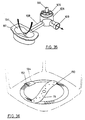
- Spray arm 75 integrally includes the wash pump casing 87 which has two delivery volutes 88 and 89 leading to outer sections 84 and 86 of the spray arm respectively.
- the junctions between the casing 87 and the outlets 88 and 89 are preferably of tangential volute formation as shown in Figure 27.
- the wash pump impeller 95 (shown in more detail in Figure 28) has blades 96 curved forwardly at their lower edges. Because in the preferred form the motor 78 is a permanent magnet, synchronous AC motor, it is important that the motor starts under no load conditions. To achieve this the static water level in the wash cavity is set to just touch the bottom of the wash pump impeller. This is indicated by the water level symbols in Figure 25. However, the centrifugal type pump employed is not self priming. It is for this reason that the impeller 95 has the axial flow type forward facing blade sections 97 on the bottom of the blades. After the motor has started under no load, the leading edges 97 of the impeller lift the liquid and the pump will prime and operate normally. These leading edges 97 also benefit the systems when the motor is rotating in the drain direction (reverse to wash direction). The now backward facing blades resist picking up the liquid and the wash pump cannot operate.
- the motor rotor 100 (figure 27) is formed using a ferrite permanent magnet embedded in a plastics casing and has a splined shaft 99 to engage and drive wash pump impeller 95.
- the motor rotor 100 incorporates on its lower plastics surface also an impeller 101 for the drain pump.
- a cross section drain pump is shown in Figure 29.
- Impeller 101 has blades 102 shaped as shown so that when the motor rotor is rotated in the direction of arrow 103 the drain pump will drain liquid from the washing chamber as will be described more particularly later.
- the drain pump is substantially prevented from pumping due to the de-optimised profile of the impeller and casing when rotating in this direction.
- impeller 105 is formed on the top surface of rotor 100.
- the eight impeller blades are about 1.5mm in height. This creates a counter flow in the drain direction. This hydrodynamic seal acts only against liquid flow by-pass. It does not prevent air bleeding from the drain pump as it primes. It will be appreciated that apart from hygiene reasons drain water back flow would cause abrasion of the rotor and contamination of the spray arm nozzles.
- the drain pump casing 106 ( Figures 25,27 and 35) is formed by providing a dose tolerance well in the floor of wash chamber 3. It is open at the top to the wash chamber 3. This well could be moulded into the floor or moulded separately and fitted later.
- the motor rotor 100 mounts within casing 106 on shaft 107. It is a feature of the invention that the motor rotor 100 is located within the wash chamber and submerged in washing liquid.
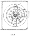
- the motor stator 111 (see also Figure 38) is located outside of the wash chamber and separated from the rotor by drain pump casing 106.
- the stator in the preferred embodiment comprises four salient poles 110 to make up a two pole pair (110a and 110b) stator.
- the drain pump casing 106 has a drain pump inlet 108 and a drain pump outlet 109.
- the arrangement shown in Figures 25 and 27 is such that disassembly of the wash system is very simple.
- the spray arm may be removed simply by lifting it off its bearing 115.
- the motor rotor 100 and the associated wash pump impeller 95 may be lifted from the well 106 by lifting the filter plate 104.
- substantially all the working parts can be readily removed to enable cleaning of the drain pump casing 106. No fastenings are needed to retain these components in their working positions.
- a similar arrangement could be used in appliances other than dishwashers, for example clothes washing machines.
- drain sump 134 (shown in Figure 27 and diagrammatically in Figure 35) is arranged in the wash chamber base 82 so that substantially all liquid in the washing chamber will drain into it.
- the drain pump inlet 108 is connected to a lowest part of the sump 120.
- the floor of the wash chamber is provided under the filter plate with a helical channel 160 having its lowest point 161 opening into the sump 120 as shown in Figure 39.
- the construction of the motor-pump combination is such that the height of the wash pump and electric motor from the highest level 121 of the spray arm 75 ( Figure 25) to the lowest level of the electric motor is very small - typically of the order of 55mm.
- the height dimension including the drain pump casing extending below the motor is 75mm.
- a nozzle 116 may be provided in the ends 86 and 84 of the spray arm 75. This provides a substantially horizontal jet of wash liquid 117a.
- the comer portions of the wash chamber wall in the plane of the jet have a shaped protuberance 118 to form deflecting vanes to deflect jet spray 117a into a substantially vertical jet 117b. This ensures vertical spray coverage in the chamber comers where rounded comers of only small radius are used well outside the spray arm diameter.
- a glass 201 is shown accommodated in a comer of the wash chamber benefiting from the deflected spray.
- the wash cycle requires the use of hot water and it is necessary to provide a heater for heating the cold water supplied to the dishwasher to an elevated temperature.
- the water heater is provided in the floor of the wash chamber as shown diagrammatically in figures 25 and 34.
- the heater is formed by a circular metal heating plate 141 which has resistive heating elements 142 in intimate thermal contact therewith on the underside.
- the heating plate 141 which is about 250mm in diameter, forms the central portion of the wash chamber floor and is sealably mounted in a circular aperture 143 provided in the floor.
- the heater plate in turn has a central aperture 144 which accommodates well casing 106 which houses the motor rotor 100 and drain pump 101. Seals 145 and 146 respectively seal the heater plate sump and floor junctions.
- Heater plate 141 is formed from porcelain enamelled steel.
- a pattern of resistance elements 142 is formed on the enamelled lower or exterior surface of the plate. These elements are fabricated using thick film technology where a resistive paste or ink is deposited or printed on the enamel substrate in the desired track pattern and then fused solid.
- the tracks may be made up of conductive and resistive portions. Power connections to the heater are made to conductive, non-heating portions 147 of the tracks. When energised the resistive tracks dissipate heat which is conducted to the steel plate and thence to the liquid in contact with the opposite surface of the plate.
- Temperature sensors may also be formed on the plate using thick film techniques to provide feedback for temperature control circuitry.
- the wash pump loading can also be monitored to provide an indication of flow and the heater switched off on detection of inadequate wash liquid flow.
- the thick film technology used can also provide thermal oven temperature protection links, inter-connections to the motor, and a termination point for connection to the motor stator windings.
- the heater plate provides a relatively large surface area (compared to conventional tubular sheathed elements) for heating the wash liquid which during the wash cycle will flow across the top surface of the plate.
- a heater of this configuration provides low power density heating and low surface temperature which improves safety and minimises the risk of thermal damage to adjacent plastics components.
- the heater plate is disposed substantially horizontally in the wash chamber floor which makes it simple to ensure a constant substantially laminar flow of wash liquid is passed over it.
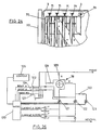
- Control of the filling, rinsing, draining and washing cycles is provided by a programmed microcomputer 120 (see Figure 26) for example a National Semiconductor COP881 C user operated microprocessor console 126 connects to the microcomputer.
- a primary function of the microcomputer 120 is control of the start up and running of synchronous motor 78, both for washing in one rotational direction and draining in the other direction.
- Motor 78 is an alternating current synchronous motor with the stator field created by windings on one or more pole pairs.
- one pole pair 110a of the stator 111 is geometrically displaced 90° to the other pole pair 110b.
- the current in one pole is phase shifted in relation to the mains current in the other pole.
- the permanent magnet (not shown) in the rotor 100 has two poles, aligned diametrically. The magnet rotates synchronously with the stator field, with an angular relationship to the stator field determined by the load.
- FIG. 26 A drive circuit which provides commutation to achieve this is shown in Figure 26.
- FIG 32 A drive circuit which provides commutation to achieve this is shown in Figure 26.
- FIG 32 Corresponding wave form diagrams are shown in Figure 32.
- the mains voltage polarity is monitored by polarity detector 127 and the magnet position is monitored by means of back EMF sensing in the stator windings 128 and 129.
- Comparators 123 and 124 detect back EMF zero crossings.
- the outputs of comparators 127, 123 and 124 are indicted by wave forms 32(b), 32(d) and 32(g) respectively.
- Other sensors could be used such as optical or Hall effect sensing.
- the stator windings are switched across the single phase AC supply by triacs 121 and 122 respectively as will be described. Switching is controlled by programmed microcomputer 120.
- the running direction of motor 78 is determined by startup commutation algorithm stored in the microcomputer. This algorithm compares instantaneous mains polarity (waveform 32(b)) with instantaneous rotor magnet position (waveform 32(b) or 329g)).
- the algorithm provides gate pulses (waveforms 32(e) and 32(h)) to the triacs 121 and 122 only if the resultant torque which would be produced is in the required direction.
- the triacs of course, once turned on, will remain on until current through each device is zero.
- the resultant stator winding currents are shown as waveforms 32(f) and 32(c), phase shifted in relation to the respective gate signals.
- the back EMF signal may be derived from the non-energised stator windings. It should be appreciated that the drive technique disclosed involves simply taking power from the mains at points in the mains cycle when a pulse of power would be beneficial for rotation of the motor. There is no attempt to synthesise commutation waveforms from a direct current supply derived from the mains.
- a method of limiting input power to the motor is applied. This is achieved by switching the triac 121 to phase angle cut the supply to stator winding 128, so regulating the current magnitude and hence controlling motor input power.
- motor torque can be monitored to infer wash pump and drain pump mode conditions such as: (i) wash pump operating normally, (ii) wash pump ventilating, (iii) low or nil water in the system, (iv) foaming of the wash liquid occurring, (v) wash pump blocked or stalled, (vi) drain pump operating normally, (vii) all liquid pumped out in drain mode and (viii) drain pump blocked or stalled.
- each pole pair winding 128 and 129 has voltage and current values referred to as V a and I a and V b and I b .
- V a and I a and V b and I b voltage and current values referred to as V a and I a and V b and I b .
- the flux return path for the salient poles is provided by a laminated iron ring 125.
- This ring also helps to structurally support the salient poles which are shaped at their extremities to "dovetail" into appropriately shaped recesses 156 in ring 125.
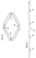
- Ring 125 is made up by stamping a continuous length of laminating strip (see Figure 43) with recesses 156 to provide for salient pole dovetails and bending into the square ring configuration shown in Figure 42.
- the blank stator material is edgewise wound in helical fashion to form a stack of laminations of the desired thickness with the square configuration shown and recesses 156 in each comer for dovetail engagement with the salient poles.
- stator in use on the dishwasher the stator is filled under the wash chamber floor so the salient poles engage circumferentially about well 106 and this line up with the permanent magnet rotor 100 mounted within the well.
- a very low height pancake shaped motor is able to be formed in this matter with the advantage that no dynamic shaft seal with the wash chamber is required due to the rotor being mounted inside the well and separated from the stator by the thickness of the well walls which lie in the motor air gap.
- the operation of a dishwasher according to the present invention is as follows.
- the drawer 17 is withdrawn from the cabinet 4 and dishes stacked in a rack within the washing chamber.
- the drawer 17 is then dosed and lid 66 simultaneously seals against the top of the wash chamber 3.
- Microcomputer 120 then initiates the manually chosen cycle of operations.
- Inlet valve 51 is opened causing the water tank to fill to the level shown in Figure 14 i.e. just below the loop of the syphon tube 55.
- the inlet valve is again opened and tank 33 filled until syphoning occurs whereupon the inlet valve is closed.
- the controlled volume of water discharged into the wash chamber 3 may be used for rinsing or washing, as selected.
- the electric motor 78 is switched on to rotate in the appropriate direction to cause the wash pump 95 to operate.
- the wash pump casing being formed by part of the spray arm there is a reaction between the pump impeller and the spray arm causing the spray arm to rotate by partial fluid coupling.
- the wash pump causes discharge of water from the spraying nozzles 76. After spraying the soiled water returns to the lower part of the washing chamber, passes through the apertures 81 in the filter plate and is drawn through the passageway 80 into the wash pump to be recirculated.
- the wash cycle is substantially similar to the rinse cycle except the water in the wash chamber will be heated during activation of the wash pump.
- the drying cycle commences. Water on the dishes is vaporised by the residual heat in the wash chamber and load.
- the tank 33 is filled with cold water 119.
- the common wall 34 will cool and water vapour in the chamber 3 produced after the final hot rinse condensed thereon. This obviates the need to vent hot water vapour from the dishwasher.
- the drawer 17 is opened and the dishes removed for storage or for use as desired.
- Detergent may be dispensed into the washing chamber by use of a detergent dispenser such as that disclosed in either our New Zealand Patent Specification 234271 dated 27 June 1990, or preferably our New Zealand Patent Specification 238504 dated 12 June 1991.
- This programme has a duration of approximately 35 minutes and water usage is 8 litres of water.
- the dishwasher of the present invention at least in one or more preferred forms, has the following advantages:
- This inlet inducer benefits the pump priming in the wash mode and helps prevent the spray arm volute priming when in the drain mode.
- the drag created by the wash pump in the drain mode is also reduced by the inlet inducer.
Landscapes
- Engineering & Computer Science (AREA)
- Water Supply & Treatment (AREA)
- Power Engineering (AREA)
- Washing And Drying Of Tableware (AREA)
- Structures Of Non-Positive Displacement Pumps (AREA)
- Combinations Of Kitchen Furniture (AREA)
- Table Devices Or Equipment (AREA)
- Assembled Shelves (AREA)
Abstract
Description
- This invention relates to dishwashers, and in particular, but not solely, domestic dishwashers.
- Conventional domestic front loading dishwashers provide two racks for stacking dishes, one in the lower zone of the wash chamber and the other in the upper zone. Such dishwashers are normally designed to fit under a typical domestic kitchen bench top with a maximum height of 900mm. Generally the lower rack is designed to take larger dishes, e.g. plates up to 280mm in diameter, and because of the overall height limitation the upper rack can only take lower height dishes. Such dishwashers lack flexibility in that they cannot efficiently wash (in a single wash) dish loads made up of a mix of dish sizes other than that dictated by the manufacturer. For example, a load of large diameter plates exceeding the number that can be accommodated in the lower rack must be cleaned using two completely separate wash cycles, even although the top rack could be empty. Further, it is not feasible to load soiled dishes unless all cleaned dishes are first removed. In addition it is not efficient to wash less than full loads. Washing must be deferred until the dishwasher has been completely filled.
- The first two problems identified above can be overcome to some extent by the use of two dishwashers. However, cost and space factors usually mean this is not a viable option. The present invention proposes a solution to the above problems by providing a smaller dishwasher intended to be used as one module in a two-module pair. The dishwasher is of very low height to allow the option of "over and under" stacking of two modules below a kitchen bench. In such an arrangement, to facilitate viewing the interior and loading the lower dishwasher, access is provided by constructing the dishwasher with a sliding wash chamber which may be withdrawn from its cabinet in the manner of a file drawer. US 2668091 discloses a sliding wash chamber, although not for the purpose of fitting two such dishwashers one above the other under a domestic kitchen bench. US 2668091 also discloses a lid to seal the open top of the wash chamber during the washing process which is supported under the roof of the dishwasher cabinet by links which allow the lid to be moved in a parallelogram motion to close onto the wash chamber as it is fully retracted into the cabinet.
- Construction of a low height machine imposes severe design constraints.
- In most conventional dishwashers components such as the wash pump and drain pump, along with associated electric motors, are mounted under the wash chamber thereby consuming height which could be available to the wash chamber. In US 3,587,939 (Nystuen et al) wash and drain pumps driven by a common induction motor are disclosed which are located inside the wash chamber and the motor is operable submerged in the wash water. A disadvantage of this system is the need to seal the motor stator from the wash liquid. A drain pump which operates with a submerged motor rotor and a stator external to the pump casing is disclosed in EP 287,984 (Askoll SPA). However this pump requires the use of two separate chambers for the motor rotor and pump impeller respectively and is not easy to service in use. Further, it is not possible to use the motor disclosed to additionally drive a wash pump.
- EP 76,739 (Esswein), EP 268,835 (Industrie Zanussi) and US 3,810,480 (Smith and Faust) disclose other constructions where the wash and drain pumps are driven by a common motor where the direction of rotation of the motor determines which pump is operable. These constructions do not significantly reduce the height requirements of the wash system.
- US 3,645,453 (Morgan) and GB 1,119,449 disclose dishwasher spray arms which incorporate as an integral part the casing of the wash pump to produce a low height wash pump located within the wash chamber. However, these systems require a motor external to the wash chamber and the need for a dynamic seal for the motor drive shaft where it passes into the wash chamber.
- A small top loading dishwasher ("Bauknecht") for mounting within a kitchen cupboard and able to be extended from the cupboard on slides has been manufactured by Philips Appliances, but this does not address the problems outlined above, and in particular requires users to lift the wash chamber lid after cupboard opening and complete withdrawal of the machine from the cupboard.
- To allow for accurate measuring of wash liquid volume, and pre-heating of water before it is dumped into a hot wash chamber, it is known to use a separate water reservoir tank fed from the household cold water supply. Such systems are disclosed in DE 3,531,095, GB 2,139,083, GB 2,139,084 (Bosch - Siemens). Further the use of such a tank filled with cold water to condense out water vapour in the wash chamber during drying cycles is disclosed in DE, 2,730,489 (Bosch - Siemens). In all of these arrangements fabricated metal tanks are used which are mounted on a metal wash chamber and this increases manufacturing costs.
- Currently available dishwashers use metal sheathed resistance heating elements mounted above the floor of the wash chamber. It is known to fabricate electrical heating elements using thick film resistors deposited on a substrate. Such heaters have been used in very low power applications such as in energy regulators. US 4,843,218 (Bosch - Siemens) proposes the use of thick film technology to fabricate an electric cooking element. Such prior art does not, however, envisage a thick film resistive heater for application in a dishwasher where efficient and direct heating of wash liquid is required.
- It is an object of the present invention to provide a dishwasher which will go some way towards overcoming the abovementioned disadvantages or which will at least provide the public with a useful choice.
In a first aspect the invention consists in a dishwasher comprising: - (a) a cabinet (4),
- (b) a wash system slidably mounted within said cabinet (4) in such a manner that it may be withdrawn horizontally out of said cabinet (4) for access thereto, said wash system including an open top wash chamber (3) adapted to accommodate dishes within which was liquid is circulated, and
- (c) a wash chamber lid (66) mounted in the top of said cabinet (4), which lid (66) is engaged with the wash chamber (3) opening to sealably close off said wash chamber (3) on horizontal retraction of the wash chamber (3) into said cabinet (4) from a position where the wash camber (3) is withdrawn, and characterised by
- (i) a vertical axis centrifugal wash pump (77) located centrally in the floor of said wash chamber (3), said pump (77) including an impeller (95), a spray arm (75) having liquid discharge nozzles (76) rotatably supported in the bottom of said wash chamber (3) for rotation about said wash pump impeller (95), said spray arm (75) having central internal upper and side surfaces which define a co-acting casing (87) for said wash pump impeller (95) and which define a volute (88, 89) which allow delivery of wash liquid pumped from said casing (87) to said nozzles (76), said spray arm central under surface being open to provide an axial flow inlet for said wash pump (77),
- (ii) means for evacuating wash liquid from said chamber,
- (iii) a first annular aperture provided in the floor of said wash chamber (3) immediately below and in registration with the wash pump inlet,
- iv) a second substantially annular aperture (81) provided in the floor of said wash chamber (3) having a diameter much greater than said first aperture, and
- (v) a plenum (80) below the floor of said wash chamber (3) which allows liquid to flow from the second annular aperture to the first annular aperture for induction up into said wash pump (77).
-
-
- Figures 1 to 3 show a selection of ways in which dishwashers according to the present invention can be mounted in modular fashion in a kitchen installation;
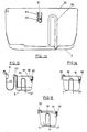
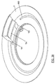
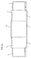
- Figure 4 is a perspective sketch of a cabinet for a dishwasher according to the invention;
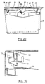
- Figure 5 is a diagrammatic cross section of one embodiment of a dishwasher according to the invention showing a wash system partially withdrawn from its cabinet;
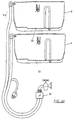
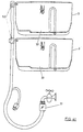
- Figures 6 to 8 show the dishwasher of Figure 5 between full retraction and full withdrawal and in particular show the wash system drain hose extension;
- Figure 9 is a diagrammatic sketch of the water supply system for a single dishwasher module;
- Figure 10 is a diagrammatic longitudinal cross section at the rear of the wash chamber showing a reservoir tank having a common wall with the wash chamber;
- Figure 11 is a diagrammatic transverse cross section through the reservoir tank;
- Figure 12 is a diametrical cross section of the lower part of the wash system showing the spray arm, wash pump, electric motor and drain pump construction;
- Figures 13 to 15 show diagrammatically transverse cross-sections of the dishwasher illustrating the filling and emptying modes for the reservoir tank;
- Figures 16 to 18 show diagrammatically longitudinal cross-sections of the dishwasher illustrating alternative filling configurations.
- Figure 19 is a diagrammatic longitudinal cross section of a dishwasher showing the position of the wash chamber lid;
- Figures 20 shows a diagrammatic view of the dishwasher lid and lid lifting mechanism;
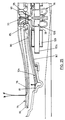
- Figure 21 is a detailed side elevation of the inner portion of the lid and lid lifter mechanism showing the lid at the start of the closing phase.
- Figure 22 is a detailed side elevation of the inner portion of the lid and lid lifter mechanism showing the lid at the completion of the closing phase.
- Figure 23 is a graph showing relative displacement of drawer, lid and lid lifter during the closing phase.
- Figure 24 is a part plan view of the wash chamber showing one form of means for holding dishes, such as plates, in position;
- Figure 25 is a part diametrical cross section of the lower part of the wash system corresponding to Figure 12 showing the water path in detail;
- Figure 26 is a block circuit diagram of the electric motor control circuit;
- Figure 27 is an exploded view of the major spray arm wash pump and motor components;
- Figure 28 is an enlargement of the wash pump impeller;
- Figure 29 is an under view of a drain pump impeller;
- Figure 30 is a part view of the spray arm and wash chamber wall showing a jet deflecting formation in the comer portion of the wash chamber wall;
- Figure 31 is a similar view to that shown in Figure 30 but showing jet deflection from straight portions of the chamber wall;
- Figure 32 is a waveform diagram of pulses formed by the motor drive circuit;
- Figure 33 is a phasor diagram illustrating motor torque monitoring;
- Figure 34 is a plan view of the underside of a heater plate showing a thick film heating element configuration;
- Figure 35 is a perspective sketch of the drain pump and associated inlet sump;
- Figure 36 is a perspective view of the bottom of the wash chamber showing a wash water filter jet cleaning system;
- Figure 37 is a diametrical cross section through the wash system showing the wash filter jet cleaning system;
- Figure 38 shows a horizontal cross section through the wash chamber drain so as to show the major wash system components even although they are mounted one above the other and are separated by partitions.
- Figure 39 is a detail of part of the wash chamber floor showing a helical drain channel;
- Figures 40 and 41 show diagrammatically two options for water hose connections two modular dishwashers forming a composite pair,
- Figure 42 shows an isometric view of the motor stator,
- Figure 43 shows a portion of the blank lamination material prior to formation as the stator of Figure 42, and
- Figure 44 is a plan view of a blank for forming the cabinet of Figure 4.
-
- In the preferred embodiments the dishwasher is constructed with a height dimension approximately half that of conventional front-loading domestic dishwashers. It is intended to be used alone or as one of a number, more usually one of a pair of such dishwashers.
- Referring to figures 1 to 3, various installation concepts using one or two dishwashers according to the present invention are shown. It is a concept of the present invention to provide a modular dishwasher unit. In Figure 1, two
such dishwashers 2 are shown stacked one above the other under asink bench 1 which will typically be between 850 and 900mm above floor level. In Figure 2 twodishwashers 2 are shown mounted one on either side of a sink forming part of thesink bench 1. In Figure 3 only asingle dishwasher 2 is provided under asink bench 1. Because of the reduced height dimension a dishwasher according to the invention could be bench mounted. Thus eachdishwasher 2 can be regarded as a modular unit which is an independent self contained dishwasher capable of accommodating any conventional dish load. - From Figure 1 it can be seen that when two
modular dishwasher units 2 are stacked one above the other the configuration is similar in external dimensions to conventional dishwashers. Twomodular units 2 installed side by side immediately under a bench top as in Figure 2 offer the same capacity as a conventional dishwasher but avoid the inconvenience of a user having to bend down to reach the lower half of the dishwasher. Additionally access is improved in that a wash chamber 3 (see Figure 5) may be slidably withdrawn from thecabinet 4 of a dishwasher unit by being mounted in the form of a drawer. - Some modular pair arrangements could be manufactured as such rather than pairing two individual modules at installation. For example the configuration shown in Figure 1 could be paired at a maintenance to mechanically link the individual dishwasher cabinets. In such an arrangement there would be advantage in combining the plumbing arrangements as will be discussed later in this specification.
- The provision of two independent dishwashers allows for considerable flexibility in operating modes.
- 1. One module operating, or two modules operating simultaneously with a mixed dish load. With each module capable of accommodating the largest item of dish load, this concept offers an increased capacity for large items.
- 2. One or both modules operating, but not necessarily simultaneously, where each module has either lightly soiled or heavily soiled dish load, and the appropriate wash programme set to suit the individual module.
- 3. One module being gradually filled with soiled dishes, while the second module is being emptied only as its clean dish load is being reused. For reasons of hygiene this is not practical with single dishwashers
- 4. One module programmed for lightly soiled loads and the other module for heavily soiled loads.
- 5. One module switched on as soon as it has been filled with soiled dishes. That is, smaller loads may be efficiently washed.
-
- Referring now to Figure 4, in the preferred form the present dishwasher cabinet is constructed from sheet metal to form a five sited box structure having a top 5 a
bottom 6 andsides cabinet 4 is flanged as a portal frame having twoportal members comers 12 and 13 to theextremities portal frame members 11 and 12 are jointed together at 16 by a very thin section of metal which in structural terms comprises essential a pin joint. Similarly, ends 14 and 15 of the portal members are effectively joined toflange section 18 by pin joints. This section effectively forms a beam to tie together the ends of the portal members. Unlike the conventional application for portal frames joint 16 is not subject to any significant load normal topanel 6. The function of the portal frame in the present application is to provide bracing against transverse loads and there is no requirement or advantage in having joint 16 moment resisting. - The portal could be inverted but the orientation shown assists in allowing clearance for a drain pump to be described later. It also means the portal frame profile substantially follows the profile of the wash chamber which itself is shaped so as to optimally hold large plates.
- One aspect of the present invention is that a dishwasher is provided whereby the wash chamber in which dishes are placed, together with all other components necessary to the wash system, is mounted within a cabinet on slides to function as a drawer. This configuration is shown in Figure 5 where a
wash chamber 3 is shown slidably mounted withincabinet 4 in a partially withdrawn position. - An aesthetically
pleasing facia 20 is fitted to the front ofwash chamber 3 and incorporates a drawer pull (not shown). When fully retracted or dosed (as shown in Figure 6)facia 20 abuts the front of thecabinet 3. - A dishwasher as described is intended for installation in an open cavity, usually under a bench, so that the
facia 20 effectively doses off the cavity and is the visible component of the dishwasher in the same manner as with conventional front loading dishwashers - Unlike the
cabinet wash chamber 3 preferably formed as a one piece plastics moulding. This has obvious advantages over sheet metal fabrication. The use of a drawer configuration means that flexible and extending cable and hose arrangements are required for running between the cabinet and the wash system. Electrical connections for the drawer mounted components could be provided by asocket 31 attached to the cabinet and aplug 32 attached to the washing chamber. Connection is made when thedrawer 17 is in the substantially fully home position. Preferably, however, fixed wiring is employed using a flexible cable loop. In this form the electrical cable could be attached compositely to the drain hose shown in Figures 6 to 8. - Water connections to and from the sliding
washing chamber 3 are arranged as follows. A drain hose 35 (Figures 6 to 8) is formed in a loop and is arranged to have acentral portion 36 transverse to the direction of movement of the chamber with twoarms drain hose arms central portion 36 so that the two arms move from a position in substantially the same plane (orthogonal angles to the direction of movement of the drawer 17) as shown in Figure 6 to the position shown in Figure 8 where the two arms are more or less in the same plane but at right angles to the position shown in Figure 6. This arrangement minimises the space required to accommodate the drainage hose when the wash chamber is in the dosed position. - The water supply management for the wash system is shown in Figure 9. A
wash hose 40 connects between adischarge spout 53 and an electrically operatedwater valve 51.Valve 51 could be a solenoid valve, for example.Valve 51 is in use coupled to a householdwash supply tap 46. Thevalve 51 is moulded to thehose 40. In addition an electrical cable is also moulded tohose 40 to provide an electrical connection to valve 41. Theelectrical connector 47 is attached to acable tail 47 allowing connection to the dishwasher controller through a cabinet mounted socket. - Wash water is supplied to a
reservoir tank 33 which is partially integrally formed with the wash chamber 3 (see Figure 10). Thechamber 3 has a dosed flange on one end wash. A moulded plastics covermember 44 is welded to the flange dry line for form thetank 33. Thetank 33 shares acommon wall 34 with the wash chamber. The use of a separate tank of much smaller horizontal cross section than that of thewash chamber 3 allows accurate metering of the volume of water used for washing. This is especially important where, as here, a relatively small change of water is used - typically 2 litres. - The manner in which the
reservoir tank 33 is used to meter water into the wash chamber will now be described with reference to Figures 11 and 13 to 15. Thewater supply hose 40 is shown connected to electrically actuatedinlet valve 51 fed from a supply of cold water. The water supply hose terminates at aspout 53 fixed to thecabinet 4.Spout 53 discharges intotank 33 only whenwash chamber 3 is in the dosed position. Alternatively a flexible hose 52 (Figure 18) may be connected from thecabinet 4 to aspout 54 fixed to thetank 33. in eithercase inlet valve 51 cannot be opened unless thewash chamber 3 is in the dosed position. An interlock switch can be provided to accomplish this or the electrical connection broken in the manner discussed above in relation to Figure 5. - Control of the filling of
tank 33 is determined by a water level sensing means 60 having a permanent magnet in afloat 61 which is able to activatereed switches Inlet valve 51 is opened and the tank is filled to a level such that thefloat 61 rises and activates the lowestlevel reed switch 62 to cause theinlet valve 51 to be dosed as indicated in Figure 14. Water is held intank 33 for a variety of purposes which will be described, but when required discharge into thewash chamber 3 occurs as follows.Inlet valve 51 is again opened to raise the water level to a level just above the top of the loop of asyphon tube 55 whereupon syphonic action occurs causing the entire contents of the tank to be dumped into thewash chamber 3 throughsyphon tube outlet 57.Upper reed switch 63 senses when the water level rises above the top ofsyphon tube 55 and theinlet valve 51 is then closed. The flow rate of the water throughvalve 51 must exceed the syphon flow rate forswitch 63 to the triggered. - Alternative methods may be used to switch
valve 51 off as soon as syphoning occurs. A sensing means can be included in the discharge leg of thesyphon 55. Alternativelyreed switch 63 can be located below the level at which syphoning occurs and the time taken to increase water level fromreed switch 62 toreed switch 63 used to calculate flow rate of the water supply. A further calculation can be made to determine the additional time required for the water level to reach that required for syphoning.Inlet valve 51 can be switched off after expiration of this calculated period of time. -
Tank 33 shares acommon wall 34 withwash chamber 3 as is best seen in Figure 11. This wall is thermally conductive and constitutes a heat exchanger between the wash chamber and reservoir tank. The plastics material used for the wash chamber may itself be sufficiently conductive to obtain adequate heat transfer or alternatively a metal wall insert can be fitted. Whentank 33 is filled prior to use for washing or hot rinsing the water will be pre-heated due to heat transfer from the heated water and interior of the wash chamber. On the other hand the cold water in the tank will tend to keepwall 34 cooler than it would otherwise be and this phenomenon is used during the drying cycle as described later. - In summary the
reservoir tank 33 configuration provides: - (a) a container in which the inlet water volume can be measured above,
- (b) a means of cooling a surface of the wash cavity so that the steamy air inside the wash cavity, at the completion of a wash programme, can condense and thereby allow the wash load to dry;
- (c) a heat exchange so that the incoming volume of inlet water can be pre-heated prior to entering the wash chamber to thereby remove the risk of thermal shock to the washload if it is at an elevated temperature, and
- (d) reduced heat up time when the liquid is transferred to the wash chamber and pre-heating occurs while the wash system is operating to thereby reduce energy usage.
-
- When two dishwashers are used in combination in the manner previously outlined they are nevertheless plumbed so as to share household fittings during installation. Two alternative methods of providing water supply are shown in Figures 40 and 41 respectively. In Figure 40 each dishwasher
water supply hose 40 is terminated on a respective outlet of adual valve 51 which is coupled to a cold water tap. Each section of the valve is controlled separately by respective controls in the two dishwashers. In Figure 41 thewater hose 40 for the top dishwasher is connected to a two-way or shuttle valve 48 which also supplies water to thespout 53 of the lower dishwasher. Valve 48 receives water fromvalve 51. Valve 48 operates to divert water between the top and bottom washers. - Because in the preferred form of the invention wash chamber 3 (and associated wash system) is arranged as a sliding drawer 17 (see Figure 19) dishes are top loaded and a
watertight lid 66 provided.Ud 66 is mounted incabinet 4 rather than thewash chamber 3 and engages with the top of the wash chamber only when thedrawer 17 is fully dosed. Thus when the drawer is withdrawn the lid is left in the cabinet The user has no direct involvement with opening and closing the lid. A lid lifting mechanism is provided to raise and lower the lid as the drawer is opened and closed, and to lock the lid down in place when the drawer is fully dosed. - The lifting mechanism includes a
sub frame 24 mounted by fourlink members 26 hinged at 27 to thesub frame 24 and hinged at 28 to aframe member 29 forming part of thecabinet 4. The links and hinges are preferably formed as a unitary moulded polypropylene or "living" hinge.Ud 66 is floatably retained by the sub-frame24A tension spring 30 biases thesub frame 24 and lid upwardly to a position in which thelid 66 is lifted away from the to ofwash chamber 3. Figure 21 shows thechamber 3 almost fully retracted at the point of lid closure. An abutment flange on chamber 3 (moving to the left) has made contact withlid 66 and contact with a portion oflid lifter 24. Further leftward movement ofchamber 3 will causelifter sub-frame 24 to rotatelink 27 anticlockwise, moving the sub-frame and lid both inwardly (to the left) and downwards. The relative displacements of the chamber (drawer), lid and lid lifter are shown graphically in Figure 23. On that graph abutment of the moving parts occurs at point A and further retraction of the chamber to point B results in the lid and lifter moving inwards (increasing value of x) downwards so that the lid damps onto to top of the open wash chamber. Provision is made for locking the lid in this position. Further retraction ofchamber 3 causes the abutment flange to ride up over the abutting portion of sub-frame 24 (which does not move further) and together with the lid 66 (which is free to slide within the sub-frame) moves to point C on the graph, being the physical position shown in Figure 22. The lid and chamber flange in this "home" position are clamped together.Buffers 21 damp the travel between points B and C. - The positioning of dishes in the
washing chamber 3 is facilitated by providing arack 70 on the bottom of the washing chamber. Slots, notches orother details 71 may be provided on at least one side wall of thewashing chamber 3 as shown in Figure 24. These details may be moulded in the washing chamber wall which is preferably a moulding of a plastics material and the arrangement is such that larger dishes for example plates and other dishes having a rim can be supported against the washing forces operating. Preferably a rack providing more conventional dish support may be used to support dishes, although in the present invention such a rack is fixed rather than slidable. However the rack must be configured to optimise the space available in the wash chamber and in this respect must allow the bottom edge of dishes (such as plate 200) to extend below the spray arm hub as shown in Figure 12. - Referring to Figures 12 and 25 the
washing chamber 3 has aspray arm 75 having spraying apertures ornozzles 76 in an upper surface thereof. A wash/rinsewater pump 77 is rotated by anelectric motor 78 and preferably this motor also rotates adrain pump 79. Theinlet 85 to thewash pump 77 is fed by an annular passageway orplenum 80 under afilter plate 104 having an annular inlet comprising a series ofapertures 81 at its periphery. Thefloor 82 of thewash chamber moulding 3 is recessed to provide the plenum. Thespray arm 75 is symmetrically curved as shown with the outer ends 86 curved downwardly from the central orhub portion 121. The purpose of this curvature is so that larger dishes (such asplate 200 shown in Figure 12) can be accommodated within the low height of thewash chamber 3. - Because of the low volume of water change used for each wash/rinse cycle (2 litres) only a low suction head is available for
wash pump 77. This means only a small pressure drop can be tolerated which means the pump velocity intake must be low. To achieve this a large water intake area is required. - As a result of the wash pump requirement for a large intake area, in order to successfully operate with a low liquid volume and a minimal suction head, the height available to incorporate the system that filters the wash liquid prior to it entering the wash pump inlet is reduced as compared with conventional dishwashers.
- As already mentioned the intake area is covered with a filter comprising an annular ring of apertures 81 (in filter plate 104) of approximately 350mm outside diameter and 300mm inside diameter. To ensure that this perforated area remains as dear as possible for the liquid to flow through, an active filter cleaning system is used. Referring to Figures 36 and 37, one or
more jets 150 are provided in thespray arm 75 to create a clearing effect on thefilter plate 104 ahead of the spray arm as it rotates. -
Large soil particles 153 are cleared off the perforations radially onto and against acircular recess 152 and rotated around the filter plate to drainsump 134 which is provided with a passive filter orstrainer 151. As with filter systems found in conventional dishwashers, thestrainer 151 will require regular servicing by the user. As shown in Figure 36 thestrainer 151 has a "mouth" configuration to scoop in the soil being cleared byjets 150. - The arrangement of the spray arm, wash pump, motor and drain pump can be understood with reference to Figure 25 and to the exploded view of Figure 27.
Spray arm 75 integrally includes thewash pump casing 87 which has twodelivery volutes outer sections casing 87 and theoutlets nozzles 90 in this section. - The wash pump impeller 95 (shown in more detail in Figure 28) has
blades 96 curved forwardly at their lower edges. Because in the preferred form themotor 78 is a permanent magnet, synchronous AC motor, it is important that the motor starts under no load conditions. To achieve this the static water level in the wash cavity is set to just touch the bottom of the wash pump impeller. This is indicated by the water level symbols in Figure 25. However, the centrifugal type pump employed is not self priming. It is for this reason that theimpeller 95 has the axial flow type forward facingblade sections 97 on the bottom of the blades. After the motor has started under no load, the leadingedges 97 of the impeller lift the liquid and the pump will prime and operate normally. These leadingedges 97 also benefit the systems when the motor is rotating in the drain direction (reverse to wash direction). The now backward facing blades resist picking up the liquid and the wash pump cannot operate. - The motor rotor 100 (figure 27) is formed using a ferrite permanent magnet embedded in a plastics casing and has a
splined shaft 99 to engage and drivewash pump impeller 95. Themotor rotor 100 incorporates on its lower plastics surface also animpeller 101 for the drain pump. A cross section drain pump is shown in Figure 29.Impeller 101 hasblades 102 shaped as shown so that when the motor rotor is rotated in the direction ofarrow 103 the drain pump will drain liquid from the washing chamber as will be described more particularly later. When the motor rotor is rotated in the opposite direction (see arrow 104) to operate the wash pump the drain pump is substantially prevented from pumping due to the de-optimised profile of the impeller and casing when rotating in this direction. There is also a non-return valve provided in thedrain pump outlet 109 to stop flow being drawn out of the drain hose into the wash chamber. - To prevent water flow by-pass around the rotor and into the wash chamber when the drain pump is working a
shallow plastics impeller 105 is formed on the top surface ofrotor 100. The eight impeller blades are about 1.5mm in height. This creates a counter flow in the drain direction. This hydrodynamic seal acts only against liquid flow by-pass. It does not prevent air bleeding from the drain pump as it primes. It will be appreciated that apart from hygiene reasons drain water back flow would cause abrasion of the rotor and contamination of the spray arm nozzles. - The drain pump casing 106 (Figures 25,27 and 35) is formed by providing a dose tolerance well in the floor of
wash chamber 3. It is open at the top to thewash chamber 3. This well could be moulded into the floor or moulded separately and fitted later. Themotor rotor 100 mounts withincasing 106 onshaft 107. It is a feature of the invention that themotor rotor 100 is located within the wash chamber and submerged in washing liquid. The motor stator 111 (see also Figure 38) is located outside of the wash chamber and separated from the rotor bydrain pump casing 106. The stator in the preferred embodiment comprises foursalient poles 110 to make up a two pole pair (110a and 110b) stator. Thedrain pump casing 106 has adrain pump inlet 108 and adrain pump outlet 109. The arrangement shown in Figures 25 and 27 is such that disassembly of the wash system is very simple. The spray arm may be removed simply by lifting it off itsbearing 115. Themotor rotor 100 and the associatedwash pump impeller 95 may be lifted from the well 106 by lifting thefilter plate 104. Thus substantially all the working parts can be readily removed to enable cleaning of thedrain pump casing 106. No fastenings are needed to retain these components in their working positions. A similar arrangement could be used in appliances other than dishwashers, for example clothes washing machines. - A preferred form of drain sump 134 (shown in Figure 27 and diagrammatically in Figure 35) is arranged in the
wash chamber base 82 so that substantially all liquid in the washing chamber will drain into it. Thedrain pump inlet 108 is connected to a lowest part of thesump 120. To further improve wash liquid drainage intosump 134 the floor of the wash chamber is provided under the filter plate with ahelical channel 160 having itslowest point 161 opening into thesump 120 as shown in Figure 39. - It is important to achieve the modular advantages earlier outlined that the construction of the motor-pump combination is such that the height of the wash pump and electric motor from the
highest level 121 of the spray arm 75 (Figure 25) to the lowest level of the electric motor is very small - typically of the order of 55mm. The height dimension including the drain pump casing extending below the motor is 75mm. - Referring to Figure 30, a
nozzle 116 may be provided in theends spray arm 75. This provides a substantially horizontal jet ofwash liquid 117a. The comer portions of the wash chamber wall in the plane of the jet have a shapedprotuberance 118 to form deflecting vanes to deflectjet spray 117a into a substantiallyvertical jet 117b. This ensures vertical spray coverage in the chamber comers where rounded comers of only small radius are used well outside the spray arm diameter. In Figure 30 aglass 201 is shown accommodated in a comer of the wash chamber benefiting from the deflected spray. - The wash cycle requires the use of hot water and it is necessary to provide a heater for heating the cold water supplied to the dishwasher to an elevated temperature.
- In the present invention the water heater is provided in the floor of the wash chamber as shown diagrammatically in figures 25 and 34. The heater is formed by a circular
metal heating plate 141 which hasresistive heating elements 142 in intimate thermal contact therewith on the underside. Theheating plate 141, which is about 250mm in diameter, forms the central portion of the wash chamber floor and is sealably mounted in a circular aperture 143 provided in the floor. The heater plate in turn has a central aperture 144 which accommodates well casing 106 which houses themotor rotor 100 anddrain pump 101. Seals 145 and 146 respectively seal the heater plate sump and floor junctions. -
Heater plate 141 is formed from porcelain enamelled steel. A pattern ofresistance elements 142 is formed on the enamelled lower or exterior surface of the plate. These elements are fabricated using thick film technology where a resistive paste or ink is deposited or printed on the enamel substrate in the desired track pattern and then fused solid. The tracks may be made up of conductive and resistive portions. Power connections to the heater are made to conductive, non-heating portions 147 of the tracks. When energised the resistive tracks dissipate heat which is conducted to the steel plate and thence to the liquid in contact with the opposite surface of the plate. Temperature sensors may also be formed on the plate using thick film techniques to provide feedback for temperature control circuitry. The wash pump loading can also be monitored to provide an indication of flow and the heater switched off on detection of inadequate wash liquid flow. The thick film technology used can also provide thermal oven temperature protection links, inter-connections to the motor, and a termination point for connection to the motor stator windings. - The heater plate provides a relatively large surface area (compared to conventional tubular sheathed elements) for heating the wash liquid which during the wash cycle will flow across the top surface of the plate. A heater of this configuration provides low power density heating and low surface temperature which improves safety and minimises the risk of thermal damage to adjacent plastics components.
- In the preferred form the heater plate is disposed substantially horizontally in the wash chamber floor which makes it simple to ensure a constant substantially laminar flow of wash liquid is passed over it. However, it would be feasible to mount the heater plate vertically and locate it in one of the side walls of the wash chamber, although not wall 34 which is common to
tank 33. - Control of the filling, rinsing, draining and washing cycles is provided by a programmed microcomputer 120 (see Figure 26) for example a National Semiconductor COP881 C user operated
microprocessor console 126 connects to the microcomputer. Thewater inlet valve 51 already referred to connected to an output ofmicrocomputer 120. - A primary function of the
microcomputer 120 is control of the start up and running ofsynchronous motor 78, both for washing in one rotational direction and draining in the other direction. -
Motor 78 is an alternating current synchronous motor with the stator field created by windings on one or more pole pairs. Referring to Figures 25, 27 and 38 in the preferred form onepole pair 110a of thestator 111 is geometrically displaced 90° to theother pole pair 110b. The current in one pole is phase shifted in relation to the mains current in the other pole. The permanent magnet (not shown) in therotor 100 has two poles, aligned diametrically. The magnet rotates synchronously with the stator field, with an angular relationship to the stator field determined by the load. - Being an AC synchronous motor, a starting method is required to bring the rotor to synchronous speed in a required direction. A drive circuit which provides commutation to achieve this is shown in Figure 26. Corresponding wave form diagrams are shown in Figure 32. The mains voltage polarity is monitored by
polarity detector 127 and the magnet position is monitored by means of back EMF sensing in thestator windings Comparators comparators triacs programmed microcomputer 120. The running direction ofmotor 78 is determined by startup commutation algorithm stored in the microcomputer. This algorithm compares instantaneous mains polarity (waveform 32(b)) with instantaneous rotor magnet position (waveform 32(b) or 329g)). The algorithm provides gate pulses (waveforms 32(e) and 32(h)) to thetriacs - The back EMF signal may be derived from the non-energised stator windings. It should be appreciated that the drive technique disclosed involves simply taking power from the mains at points in the mains cycle when a pulse of power would be beneficial for rotation of the motor. There is no attempt to synthesise commutation waveforms from a direct current supply derived from the mains.
- When the microcomputer determines from back EMF zero crossing frequency that the rotor speed is dose to synchronous with the rotating stator field the motor is switched to run directly from the mains as a split phase motor without any need for electronic commutation. It will be appreciated that during electronic commutation only one stator winding is energised at any one time and this limits the motor power. For synchronous running
triac 121 remains ON to connect windingpair 128 across the mains whiletriac 122 is switched OFF. At thesame time triac 123 is switched ON to energise winding 129 pair via resistor-capacitor network 133 which applies a 90° lagging current to that winding pair. - To enable the motor to run over the range of input voltage and output power required, a method of limiting input power to the motor is applied. This is achieved by switching the
triac 121 to phase angle cut the supply to stator winding 128, so regulating the current magnitude and hence controlling motor input power. - With a motor and motor control system as described motor torque can be monitored to infer wash pump and drain pump mode conditions such as: (i) wash pump operating normally, (ii) wash pump ventilating, (iii) low or nil water in the system, (iv) foaming of the wash liquid occurring, (v) wash pump blocked or stalled, (vi) drain pump operating normally, (vii) all liquid pumped out in drain mode and (viii) drain pump blocked or stalled.
- The motor torque is monitored as follows. Referring to Figure 33 each pole pair winding 128 and 129 has voltage and current values referred to as Va and Ia and Vb and Ib. When the microcomputer compares the value of the relationship between these two phase angles with a range of pre-determined values, the degree of potential torque output of the motor at that time, can be determined.
- When the motor runs in the reverse direction for draining, the start up method is unchanged. However, when synchronous or near synchronous speed is detected, and run mode is selected, only one set of poles continue to operate - that is, the motor becomes a single pole pair motor. The additional complexity required to run on both pole pairs in the reverse direction is unnecessary as less power is required to operate the drain pump. The motor run mode for the applications described does not involve commutation from the drive circuit, but in other low power applications the motor could be permanently commutated by the drive circuit. The configuration of the motor stator can be seen in Figure 27. Two orthogonal
salient pole pairs windings - The flux return path for the salient poles is provided by a
laminated iron ring 125. This ring also helps to structurally support the salient poles which are shaped at their extremities to "dovetail" into appropriately shapedrecesses 156 inring 125. -
Ring 125 is made up by stamping a continuous length of laminating strip (see Figure 43) withrecesses 156 to provide for salient pole dovetails and bending into the square ring configuration shown in Figure 42. The blank stator material is edgewise wound in helical fashion to form a stack of laminations of the desired thickness with the square configuration shown and recesses 156 in each comer for dovetail engagement with the salient poles. - in use on the dishwasher the stator is filled under the wash chamber floor so the salient poles engage circumferentially about well 106 and this line up with the
permanent magnet rotor 100 mounted within the well. A very low height pancake shaped motor is able to be formed in this matter with the advantage that no dynamic shaft seal with the wash chamber is required due to the rotor being mounted inside the well and separated from the stator by the thickness of the well walls which lie in the motor air gap. - The operation of a dishwasher according to the present invention is as follows. The
drawer 17 is withdrawn from thecabinet 4 and dishes stacked in a rack within the washing chamber. Thedrawer 17 is then dosed andlid 66 simultaneously seals against the top of thewash chamber 3.Microcomputer 120 then initiates the manually chosen cycle of operations.Inlet valve 51 is opened causing the water tank to fill to the level shown in Figure 14 i.e. just below the loop of thesyphon tube 55. The inlet valve is again opened andtank 33 filled until syphoning occurs whereupon the inlet valve is closed. The controlled volume of water discharged into thewash chamber 3 may be used for rinsing or washing, as selected. If rinsing washing is required theelectric motor 78 is switched on to rotate in the appropriate direction to cause thewash pump 95 to operate. As a result of the wash pump casing being formed by part of the spray arm there is a reaction between the pump impeller and the spray arm causing the spray arm to rotate by partial fluid coupling. At the same time the wash pump causes discharge of water from the sprayingnozzles 76. After spraying the soiled water returns to the lower part of the washing chamber, passes through theapertures 81 in the filter plate and is drawn through thepassageway 80 into the wash pump to be recirculated. - The wash cycle is substantially similar to the rinse cycle except the water in the wash chamber will be heated during activation of the wash pump.
- When a cycle of washing has been completed, for example, a cold rinse, the
electric motor 78 is stopped and its direction of rotation reversed. As a result thedrain pump impeller 101 is operated to drain rinse water from the wash chamber through thehose 37 for delivery to waste. After drainage has been completed, refilling of the washing chamber takes place in the manner described. - At the completion of the wash programme the drying cycle commences. Water on the dishes is vaporised by the residual heat in the wash chamber and load. The
tank 33 is filled with cold water 119. Thecommon wall 34 will cool and water vapour in thechamber 3 produced after the final hot rinse condensed thereon. This obviates the need to vent hot water vapour from the dishwasher. When the drying cycle is completed thedrawer 17 is opened and the dishes removed for storage or for use as desired. - Detergent may be dispensed into the washing chamber by use of a detergent dispenser such as that disclosed in either our New Zealand Patent Specification 234271 dated 27 June 1990, or preferably our New Zealand Patent Specification 238504 dated 12 June 1991.
- By way of example only a typical wash programme for a moderately soiled load is set out below:
- 1) Dishwasher loaded, programme selected and switched on.
- 2) Controller turns on inlet valve and syphon starts and tub fills (tank already fill up to pre-syphon point from previous use).
- 3) Wash pump starts for a cold pre-rinse. No heating occurs. 3 minute duration.
- 4) Wash pump stops, motor reverses and pumps out wash liquid.
- 5) Tub refills and wash pump re-starts for main wash. Heater switches on, until temperature reaches 65°C. At 45°C the detergent dispenser releases its detergent.
- 6) When 65°C is reached, heater turns off. Washing continues. Tank fills to pre-syphon point and is pre-heated by the hot wash liquid in the tub.
- 7) After 5 minutes after reading 65°C, washing stops, motor reverses and drains tub.
- 8) Tub fills with pre-heated liquid, for first post rinse. No heating this rinse. Tank refills to pre-syphon point and pre-heats.
- 9) After three minutes washing stops, liquid pumped out, pre-heated liquid fills tub.
- 10) Final rinse begins, with heater up to 65°C. At 55°C rinse aid is dispensed.
- 11) At 65°C final pump out occurs.
- 12) At completion of pumpout, tank refills to pre-syphon point and drying cycle commences.
- 13) After approximately 30 minutes, wash load is ready for removal if desired.
-
- This programme has a duration of approximately 35 minutes and water usage is 8 litres of water.
- The dishwasher of the present invention, at least in one or more preferred forms, has the following advantages:
-
- The permanent magnet rotor runs in the wash liquid thereby precluding any need for contacting dynamic seals to contain liquid in the system.
- The permanent magnet, synchronous type motor is a comparatively high efficiency motor which does not require forced cooling.
- The chosen pole configuration allows for the shallow height of motor (in the axial direction).
- Simple and reliable electronic starting method.
- The motor operating principle and self monitoring system ensures constant, synchronous operation. If asynchronous running is detected, the motor will stop and restart automatically. The motor has two pole pairs to achieve the high torque required and has the second set of poles capacitor shifted 90- to minimise the electronics required.
- When running in reverse, the motor uses one pole pair to also reduce the electronic componentry required.
-
- The placement of the wash pump inside the spray arm removes the need for any of the conventional pipework connecting the two devices. This means that there is practically no 'dead' volume in the system, minimising the liquid volume required for the pump to operate.
- Also, this absence of pipework means losses are minimised i.e. high hydraulic efficiency.
- Spray arm rotation is created by the partial fluid coupling between the
wash pump impeller and the pump volute. Rotation speed adjustment
can be made by using a small degree of reaction from jets. Normally in
prior arrangements the pump is a separate unit situated below the sump
and connected to the spray arm by means of pipe work. Some
dishwashers have the pump housing as part of the sump. Such systems
are disadvantageous for the following reasons.
- a) The vertical space requirement of a separate pump and spray arm precludes the possibility of designing an extremely compact dishwasher.
- b) The often complicated pipe work accounts for inefficiencies through friction losses.
- c) The plumbing between the pipe and spray arm is a dead volume for washing liquid and opposes efforts to reduce liquid consumption. The present invention at least in the preferred form, is aimed at overcoming these disadvantages and providing the following further advantages.
- a) A pump and spray system wherein centrifugal type pump is mounted integrally with a rotating spray arm. The pump discharges the wash liquid directly into the arms of the spray arm without intervening plumbing.
- b) The compactness of pump and spray system facilitates maximal usable space within a given dishwasher height or for a given load capacity thus promoting the design of compact dishwashers.
- c) Because there is no pipe work between the pump and the spray arm and hence no frictional losses the overall efficiency is vastly improved compared to conventional systems. This results in smaller power requirements for the motor.
- d) Because of the lack of pipe work there is an absolute minimum volume in the system requiring filling before the system operates which facilitates low water usage and reduced energy consumption.
- e) By virtue of the fluid coupling between the pump impeller and the pump housing, power to rotate the spray arm is transmitted from the impeller to the spray arm. Therefore conventional reaction jets which may be used but are preferably not used, use additional wash liquid and do not usually contribute to the wash action.
- f) It is possible to produce the complete pump and spray system in two parts, one being the spray arm pump housing and the other being the pump impeller, the system is therefore intrinsically simple.
- g) Should the pump malfunction because of a blockage, lifting off the spray arm exposes the impeller and other parts for cleaning.
- h) Separate bearing systems for a pump and a spray arm are avoided.
- i) Rationalisation of parts reduces manufacturing costs.
- j) As no connections are necessary between the pump outlet pipe work and spray arm which are usually outside the dishwasher tub the potential of leaks in this area is removed.
- To enable the washing pump to operate without ventilating (pumping air) and with only minimal suction head available, a large intake area for the pump is employed. The pump intake is an annular area at approximately 300mm diameter and approximately 7mm high. This allows for a pump performance in the range of 65 litres/minute at a head of 2 metres that requires only 2 litres of liquid in which to operate.
- The wash pump impeller is of the mixed flow type, with a radial centrifugal outlet and an optimised axial flow inducer at the inlet.
- This inlet inducer benefits the pump priming in the wash mode and helps prevent the spray arm volute priming when in the drain mode. The drag created by the wash pump in the drain mode is also reduced by the inlet inducer.
- Both these benefits reduce the drain mode power requirements, aiding the motor running on one pair of poles - as a result of the improved priming ability of this pump, the wash pump intake is successfully located below the wash pump housing.
-
- The drain pump impeller is an adaptation of a paddle type pump that is optimised in such a way that the maximum pumping performance is achieved in the drain mode, yet the opposite direction i.e. wash mode, no pumping occurs and low drag is generated. The low drag generated when the drain pump is operating in reverse means that there is maximum motor power available to drive the wash pump.
- The drain impeller detail is moulded integrally with the motor rotor.
- The drain pump housing is integral with the motor housing and central plain bearing for the rotor.
- Should the drain pump become blocked, jammed or require any
servicing it can be accessed by removing the
spray arm 75, thefilter plate 104 which will also lift themotor rotor 100 off itsbearing shaft 99, revealing thedrain pump housing 100 which also forms the rotor housing. - Upon drain pump startup, any unwanted air present in the drain pump can escape up between the motor rotor and the motor housing. To check the flow of wash liquid through this path after the air has been passed, a centrifugal pump impeller detail is moulded on the top face of the motor rotor which in effect opposes the flow of any liquid trying to escape.
Claims (6)
- A dishwasher comprising:characterised by(a) a cabinet (4),(b) a wash system slidably mounted within said cabinet (4) in such a manner that it may be withdrawn horizontally out of said cabinet (4) for access thereto, said wash system including an open top wash chamber (3) adapted to accommodate dishes within which wash liquid is circulated, and(c) a wash chamber lid (66) mounted in the top of said cabinet (4), which lid (660 is engaged with the wash chamber (3) opening to sealably close off said wash chamber (3) on horizontal retraction of the wash chamber (3) into said cabinet (4) from a position where the wash chamber (3) is withdrawn, and(i) a vertical axis centrifugal wash pump (77) located centrally in the floor of said wash chamber (3), said pump (77) including an impeller (95), a spray arm (75) having liquid discharge nozzles (76) rotatably supported in the bottom of said wash chamber (3) for rotation about said wash pump impeller (95), said spray arm (75) having central internal upper and side surfaces which define a co-acting casing (87) for said wash pump impeller (95) and which define a volute (88, 89) which allows delivery of wash liquid pumped from said casing (87) to said nozzles (76), said spray arm central under surface being open to provide an axial flow inlet for said wash pump (77),(iii) means for evacuating wash liquid from said chamber (3),(iii) a first annular aperture provided in the floor of said wash chamber (3) immediately below and in registration with the wash pump inlet,(iv) a second substantially annular aperture (81) provided in the floor of said wash chamber (3) having a diameter much greater than said first aperture, and(v) a plenum (80) below the floor of said wash chamber (3) which allows liquid to flow from the second annular aperture to the first annular aperture for induction up into said wash pump (77).
- A dishwasher according to Claim 1 wherein said evacuating means includes a drain hose (35) and said drain hose (35) is flexible and is configured as a loop when the wash system is fully retracted which can open out to allow said hose to extend with withdrawal of the wash system from said cabinet (4),
said loop being provided with a straight length (36) oriented transversely to the direction of movement of said wash system and a pair of arms (37, 38) extending from either end of said straight length (36), one said arm (37) extending to said cabinet (4) and the other said arm extending to said wash system such that when the wash system is fully retracted the loop occupies a space between the wash system and the cabinet (4) which does not exceed the outside diameter of the drain hose (35). - A dishwasher according to any one of the Claims 1 and 2 wherein said lid (66) is mounted in said cabinet by four hinged link members (26), one end (28) of each member (26) being hingably connected to said cabinet (4) and the other end (27) of each member (26) being hingably connected to said lid (66) to provide the lid (66) with two degrees of freedom such that an inwardly directed force causes said lid (66) to move inwardly and downwardly and an outwardly directed force causes said lid to move outwardly and upwardly, and complementary abutting means provided on said lid (66) and said wash chamber (3), said means abutting on substantially full retraction of said wash chamber (3) within said cabinet (4) and on initial withdrawal of said wash chamber (3) from within said cabinet (4) with continued displacement of said wash chamber (3) from within said cabinet (4) with continued displacement of said wash chamber (3) after abutment providing respective closing and opening forces to said lid (66) to cause it to close against or open away from said wash chamber opening.
- A dishwasher as claimed in any one of Claims 1 to 3 wherein a water discharge spout (53) is mounted in an upper position within said cabinet (4) such that when said wash system is fully retracted within said cabinet a portion of said wash chamber (3) is located under said spout to be capable of receiving a discharge from said spout, a water hose (40) is connected at one end to said discharge spout (53) and adapted at the other end to connect in use to a water supply connection (46).
- A dishwasher combination wherein said combination comprises two dishwashers each as claimed in Claim 4 and said water hoses are each connected to one outlet of dual electrically operated valves, said dual valve having a common connection adapted to connect in use to a household cold water tap.
- A dishwasher combination wherein said combination comprises two dishwashers each as claimed in Claim 4 and the outlets of a first electrically operated two-way valve provide the cold water supply connections for each dishwasher, and including a second electrically operated valve adapted to connect in use to a household cold water supply tap and a water hose connecting the outlet of said second electrically operated valve to the inlet of said two-way valve.
Applications Claiming Priority (3)
| Application Number | Priority Date | Filing Date | Title |
|---|---|---|---|
| NZ24109391 | 1991-12-20 | ||
| NZ24109391 | 1991-12-20 | ||
| EP93900472A EP0618779B1 (en) | 1991-12-20 | 1992-12-18 | Dishwasher |
Related Parent Applications (2)
| Application Number | Title | Priority Date | Filing Date |
|---|---|---|---|
| EP93900472A Division EP0618779B1 (en) | 1991-12-20 | 1992-12-18 | Dishwasher |
| EP93900472.7 Division | 1993-07-20 |
Publications (3)
| Publication Number | Publication Date |
|---|---|
| EP0807398A2 EP0807398A2 (en) | 1997-11-19 |
| EP0807398A3 EP0807398A3 (en) | 1998-12-16 |
| EP0807398B1 true EP0807398B1 (en) | 2004-03-03 |
Family
ID=19923839
Family Applications (11)
| Application Number | Title | Priority Date | Filing Date |
|---|---|---|---|
| EP97111870A Expired - Lifetime EP0807399B1 (en) | 1991-12-20 | 1992-12-18 | Dishwasher |
| EP03010049A Expired - Lifetime EP1346679B1 (en) | 1991-12-20 | 1992-12-18 | Dishwasher |
| EP97111873A Revoked EP0807400B1 (en) | 1991-12-20 | 1992-12-18 | Dishwasher |
| EP06010182A Withdrawn EP1700557A3 (en) | 1991-12-20 | 1992-12-18 | Dishwasher |
| EP03010054A Expired - Lifetime EP1346680B1 (en) | 1991-12-20 | 1992-12-18 | Dishwasher |
| EP97111843A Expired - Lifetime EP0807396B1 (en) | 1991-12-20 | 1992-12-18 | Dishwasher |
| EP97111865A Expired - Lifetime EP0807397B1 (en) | 1991-12-20 | 1992-12-18 | Dishwasher |
| EP03009329A Expired - Lifetime EP1334689B1 (en) | 1991-12-20 | 1992-12-18 | Dishwasher |
| EP06005951A Expired - Lifetime EP1674028B1 (en) | 1991-12-20 | 1992-12-18 | Dishwasher with a thick film heating plate |
| EP93900472A Expired - Lifetime EP0618779B1 (en) | 1991-12-20 | 1992-12-18 | Dishwasher |
| EP97111849A Expired - Lifetime EP0807398B1 (en) | 1991-12-20 | 1992-12-18 | Dishwasher |
Family Applications Before (10)
| Application Number | Title | Priority Date | Filing Date |
|---|---|---|---|
| EP97111870A Expired - Lifetime EP0807399B1 (en) | 1991-12-20 | 1992-12-18 | Dishwasher |
| EP03010049A Expired - Lifetime EP1346679B1 (en) | 1991-12-20 | 1992-12-18 | Dishwasher |
| EP97111873A Revoked EP0807400B1 (en) | 1991-12-20 | 1992-12-18 | Dishwasher |
| EP06010182A Withdrawn EP1700557A3 (en) | 1991-12-20 | 1992-12-18 | Dishwasher |
| EP03010054A Expired - Lifetime EP1346680B1 (en) | 1991-12-20 | 1992-12-18 | Dishwasher |
| EP97111843A Expired - Lifetime EP0807396B1 (en) | 1991-12-20 | 1992-12-18 | Dishwasher |
| EP97111865A Expired - Lifetime EP0807397B1 (en) | 1991-12-20 | 1992-12-18 | Dishwasher |
| EP03009329A Expired - Lifetime EP1334689B1 (en) | 1991-12-20 | 1992-12-18 | Dishwasher |
| EP06005951A Expired - Lifetime EP1674028B1 (en) | 1991-12-20 | 1992-12-18 | Dishwasher with a thick film heating plate |
| EP93900472A Expired - Lifetime EP0618779B1 (en) | 1991-12-20 | 1992-12-18 | Dishwasher |
Country Status (17)
| Country | Link |
|---|---|
| US (6) | US5470142A (en) |
| EP (11) | EP0807399B1 (en) |
| JP (9) | JP3215422B2 (en) |
| KR (1) | KR100239936B1 (en) |
| AT (10) | ATE260596T1 (en) |
| AU (6) | AU669144B2 (en) |
| BR (1) | BR9206966A (en) |
| CA (10) | CA2378129C (en) |
| DE (10) | DE69231002T2 (en) |
| DK (8) | DK1346680T3 (en) |
| ES (3) | ES2210422T3 (en) |
| FI (1) | FI106919B (en) |
| NO (6) | NO313906B1 (en) |
| NZ (4) | NZ286273A (en) |
| SG (4) | SG120128A1 (en) |
| WO (1) | WO1993012706A1 (en) |
| ZA (1) | ZA929878B (en) |
Families Citing this family (209)
| Publication number | Priority date | Publication date | Assignee | Title |
|---|---|---|---|---|
| KR960010942B1 (en) * | 1993-12-01 | 1996-08-14 | 엘지전자 주식회사 | Spray Arm Rotator in Dishwasher |
| DE19639123C1 (en) * | 1996-09-24 | 1997-11-20 | Daimler Benz Aerospace Airbus | Dishwasher for aircraft catering, especially for drinking vessels |
| NZ314155A (en) | 1997-01-30 | 1999-07-29 | Fisher & Paykel | Dishwasher detergent dispenser located in door recess, having open top and being flushed out by overhead nozzle |
| AU738211B2 (en) * | 1997-01-30 | 2001-09-13 | Fisher & Paykel Appliances Limited | Dishwasher |
| AU742014B2 (en) * | 1997-01-30 | 2001-12-13 | Fisher & Paykel Appliances Limited | Dishwasher |
| US5934298A (en) * | 1997-11-14 | 1999-08-10 | Singh; Baljit | Combination sink and dishwasher |
| AU9198398A (en) * | 1997-08-16 | 1999-03-08 | Baljit Singh | Combination sink and dishwasher |
| USD438677S1 (en) | 1998-09-21 | 2001-03-06 | Maytag Corporation | Dishwasher double door |
| US6491049B1 (en) | 1998-09-21 | 2002-12-10 | Maytag Corporation | Lid construction for drawer dishwasher |
| US6460555B1 (en) | 1998-09-21 | 2002-10-08 | Maytag Corporation | Dual dishwasher construction |
| USD421162S (en) * | 1998-09-21 | 2000-02-22 | Maytag Corporation | Dishwasher door having curved top edge |
| US6260565B1 (en) | 1998-09-21 | 2001-07-17 | Maytag Corporation | Double dishwasher |
| US6363756B1 (en) | 1998-11-09 | 2002-04-02 | Fisher & Paykel Limited | Top loading laundry appliance |
| US6082386A (en) * | 1998-12-09 | 2000-07-04 | Patent Category Corp. | Vertically stacked collapsible structures |
| DE19858137B4 (en) * | 1998-12-16 | 2016-12-15 | BSH Hausgeräte GmbH | Heating for heating the rinsing liquid in a dishwasher |
| NZ516951A (en) | 1999-10-08 | 2003-10-31 | Fisher & Paykel Appliances Ltd | Linkage arrangement for wash chamber closure of dishwasher |
| IT248152Y1 (en) * | 1999-11-15 | 2002-12-10 | Electrolux Zanussi Elettrodome | DISHWASHER WITH REMOVABLE DRAWER |
| US6289908B1 (en) | 1999-12-01 | 2001-09-18 | Marjorie K. Kelsey | Double dishwasher |
| ITPN20000011A1 (en) * | 2000-02-15 | 2001-08-15 | Electrolux Zanussi Elettrodome | DISHWASHER PERFECTED EQUIPPED WITH AN ELECTRO-HYDRAULIC FUNCTIONAL UNIT |
| US6431188B1 (en) * | 2000-04-03 | 2002-08-13 | Whirlpool Corporation | Dishwasher spray arm feed system |
| NZ503866A (en) | 2000-04-10 | 2003-01-31 | Fisher & Paykel Appliances Ltd | Dishwasher with sliding drawer type wash chamber(s) in cabinet with seal formed by motor driving linkages pulling top lid down onto open top(s) fo chamber(s) |
| IT1318290B1 (en) * | 2000-07-31 | 2003-07-28 | Candy Spa | APPARATUS FOR WATER HEATING IN A DISHWASHER MACHINE. |
| CN1218082C (en) * | 2000-10-12 | 2005-09-07 | Lg电子株式会社 | Drawer like washing machine and method for washing clothes with same |
| DE10053415A1 (en) | 2000-10-27 | 2002-05-29 | Bsh Bosch Siemens Hausgeraete | Electric radiator |
| NZ512503A (en) * | 2000-11-13 | 2002-11-26 | Lg Electronics Inc | Drawer-type washing machine and locking method thereof |
| KR100399326B1 (en) * | 2000-12-11 | 2003-09-26 | 엘지전자 주식회사 | Structure for sealing of dish washer which is of drawer type |
| KR100377622B1 (en) * | 2000-12-11 | 2003-03-26 | 엘지전자 주식회사 | Structure for sealing of dish washer which is of drawer type |
| DE10064120A1 (en) | 2000-12-21 | 2002-06-27 | Bsh Bosch Siemens Hausgeraete | Method for operating a dishwasher and dishwasher |
| DE10064121A1 (en) * | 2000-12-21 | 2002-06-27 | Bsh Bosch Siemens Hausgeraete | Method for operating a dishwasher and dishwasher |
| DE10065637A1 (en) * | 2000-12-29 | 2002-07-04 | Bsh Bosch Siemens Hausgeraete | dishwasher |
| ITPN20010005A1 (en) | 2001-01-25 | 2002-07-25 | Sole Spa | MOTOPOMPA |
| US6659114B2 (en) * | 2001-02-15 | 2003-12-09 | X-Stream Technologies Ii, Llc | Automated kitchenware washer |
| US7578305B2 (en) | 2001-02-15 | 2009-08-25 | Steelkor, L.L.C. | Kitchenware washers and related methods |
| US7763119B2 (en) | 2005-04-22 | 2010-07-27 | Steelkor, L.L.C. | Kitchenware washers and methods of manufacturing the same |
| US7475698B2 (en) | 2005-04-22 | 2009-01-13 | Steelkor, L.L.C. | Kitchenware washers and methods of manufacturing the same |
| US7527062B2 (en) | 2001-02-15 | 2009-05-05 | Steelkor, L.L.C. | Kitchenware washers and methods of manufacturing the same |
| DE10110186B4 (en) * | 2001-03-02 | 2007-02-15 | Robert Sporer | Washing device for cleaning objects such as machine parts or the like |
| USD461284S1 (en) | 2001-07-23 | 2002-08-06 | General Electric Company | Dishwasher lower spray arm |
| DE20122797U1 (en) * | 2001-11-07 | 2007-11-15 | Diehl Ako Stiftung & Co. Kg | Electric pump for a dishwasher |
| US20030084928A1 (en) * | 2001-11-07 | 2003-05-08 | Wood John T. | Control for multiple compartment dishwasher |
| ITUD20010185A1 (en) * | 2001-11-19 | 2003-05-19 | Internat Steel Co Spa | WASHING MACHINE |
| DE10163192A1 (en) * | 2001-12-21 | 2003-07-03 | Bsh Bosch Siemens Hausgeraete | Method for determining the energy and water consumption of dishwashers and dishwashers |
| US7069181B2 (en) | 2001-12-21 | 2006-06-27 | BSH Bosch und Siemens Hausgeräte | Method of determining the energy and water consumption of dishwashers, and dishwashers |
| EP1536043B1 (en) * | 2002-06-18 | 2011-03-02 | Sumitomo Electric Industries, Ltd. | N-type semiconductor diamond producing method and semiconductor diamond |
| JP3974017B2 (en) * | 2002-11-05 | 2007-09-12 | 松下電器産業株式会社 | Dishwasher |
| JP3645884B2 (en) * | 2002-11-05 | 2005-05-11 | 松下電器産業株式会社 | Dishwasher |
| DE60223265T2 (en) * | 2002-11-28 | 2008-08-21 | Whirlpool Corp., Benton Harbor | Dishwasher with flat filter device comprising areas with different hole dimensions |
| WO2004058036A1 (en) * | 2002-12-30 | 2004-07-15 | Arçelik A.S. | A dishwashing apparatus |
| EP1443635B1 (en) * | 2003-01-21 | 2009-10-07 | Grundfos A/S | Method for controlling a firing angle and single phase AC fed electric motor |
| DE10352487A1 (en) * | 2003-07-22 | 2005-02-10 | BSH Bosch und Siemens Hausgeräte GmbH | Pump with integrated motor |
| WO2005018407A2 (en) * | 2003-08-26 | 2005-03-03 | Alpert Martin A | Dishwasher and method |
| US7472712B2 (en) * | 2003-09-05 | 2009-01-06 | Whirlpool Corporation | Dishwasher filter |
| US7426933B2 (en) * | 2003-09-25 | 2008-09-23 | Maytag Corporation | Dishwasher with kinetic energy water distribution system |
| ES2305705T3 (en) | 2004-01-16 | 2008-11-01 | Askoll Holding S.R.L. | PROCEDURE FOR DRIVING A BIDIRECTIONAL MOTOR TO TURN A CIRCULATION PUMP. |
| ES2373550T3 (en) * | 2004-03-10 | 2012-02-06 | Whirlpool Corporation | DISHWASHER MACHINE. |
| CN1946326B (en) † | 2004-03-16 | 2010-09-01 | 阿塞里克股份有限公司 | Dish washer and control method thereof |
| DE102004016270B4 (en) * | 2004-04-02 | 2006-02-23 | Boesche Marketing Gmbh | Cleaning device with at least one cleaning area, preferably dishwasher |
| EP1595489B1 (en) * | 2004-05-12 | 2007-07-11 | Askoll Holding S.r.l. | Fluid circulation pump with synchronous motor, equipped with heating means of the fluid, in particular for washing-machines |
| DE102004030014A1 (en) * | 2004-06-22 | 2006-01-12 | Premark Feg L.L.C., Wilmington | Dishwasher operating method and conveyor dishwashing machine |
| KR20050122354A (en) * | 2004-06-24 | 2005-12-29 | 엘지전자 주식회사 | A heater mounting structure of a dish washer |
| KR20050122360A (en) * | 2004-06-24 | 2005-12-29 | 엘지전자 주식회사 | A sump structure of a dish washer |
| KR101052964B1 (en) | 2004-06-24 | 2011-07-29 | 엘지전자 주식회사 | Motor fixing structure of dishwasher |
| NZ533978A (en) * | 2004-07-06 | 2006-04-28 | Fisher & Paykel Appliances Ltd | Appliance fault monitor |
| US20070251555A1 (en) * | 2004-09-16 | 2007-11-01 | Lg Electronics, Inc. | Dishwasher |
| KR20060035086A (en) * | 2004-10-21 | 2006-04-26 | 엘지전자 주식회사 | dish washer |
| NZ536816A (en) * | 2004-11-24 | 2006-02-24 | Fisher & Paykel Appliances Ltd | Dishwasher with sliding chamber drawer sealing to cabinet via permanent magnetic material |
| US7610923B2 (en) * | 2005-02-09 | 2009-11-03 | Maytag Corporation | Pump and filter system for a drawer-type dishwasher |
| US7870863B2 (en) * | 2005-02-09 | 2011-01-18 | Maytag Corporation | Multi-use sump for a drawer-type dishwaher |
| US8551255B2 (en) * | 2005-02-09 | 2013-10-08 | Whirlpool Corporation | Rapid heat system for a multi-tub dishwasher |
| US7862665B2 (en) * | 2005-02-09 | 2011-01-04 | Maytag Corporation | Pump system for a drawer-type dishwasher |
| US7621284B2 (en) * | 2005-02-09 | 2009-11-24 | Maytag Corporation | Pressure relief system for a dishwasher pump assembly |
| EP1757278A1 (en) | 2005-08-23 | 2007-02-28 | NOLabs AB | Device, system, and method comprising microencapsulated liquid for release of nitric oxide from a polymer |
| US9265400B2 (en) | 2005-04-22 | 2016-02-23 | Duke Manufacturing Co. | Commercial kitchenware washers and related methods |
| ATE380497T1 (en) * | 2005-04-22 | 2007-12-15 | Electrolux Home Prod Corp | BUILT-IN DISHWASHER |
| US20060237048A1 (en) * | 2005-04-25 | 2006-10-26 | Viking Range Corporation | Dishwasher incorporating a pump prime sensing system for managing a filtration system |
| US7775223B2 (en) * | 2005-11-29 | 2010-08-17 | Maytag Corporation | Flexible utility link for a drawer-type dishwasher |
| US7850784B2 (en) * | 2005-11-29 | 2010-12-14 | Maytag Corporation | Lid seal for a drawer-type dishwasher |
| US7363093B2 (en) * | 2005-11-29 | 2008-04-22 | Whirlpool Corporation | Control system for a multi-compartment dishwasher |
| US7607444B2 (en) * | 2005-11-29 | 2009-10-27 | Maytag Corporation | Latching and sealing mechanism for a drawer-type dishwasher |
| CN2916195Y (en) | 2006-01-26 | 2007-06-27 | 江门市汉宇电器有限公司 | A centrifugal drainage pump |
| NZ553187A (en) | 2006-02-10 | 2007-09-28 | Fisher & Paykel Appliances Ltd | Drawer style dishwasher of reduced height and increased width with two separate rotating head spray arms |
| US7568487B2 (en) | 2006-04-20 | 2009-08-04 | Maytag Corporation | Lid mechanism for a drawer-type dishwasher |
| US7624745B2 (en) * | 2006-04-20 | 2009-12-01 | Maytag Corporation | Drawer-type dishwasher having modular support body |
| US7695571B2 (en) * | 2006-04-20 | 2010-04-13 | Maytag Corporation | Wash/rinse system for a drawer-type dishwasher |
| US20070246069A1 (en) * | 2006-04-20 | 2007-10-25 | Maytag Corp. | Method and apparatus for selectively releasing a rinse aid in a dishwasher |
| DE102006023856A1 (en) * | 2006-05-19 | 2007-11-22 | Aweco Appliance Systems Gmbh & Co. Kg | Pumping device for use in e.g. dishwasher, has electric motor implemented as single phase synchronous motor for driving impeller, where impeller has shovel with hydraulic unit that determines driving direction of motor |
| KR101270538B1 (en) * | 2006-07-12 | 2013-06-03 | 삼성전자주식회사 | A tableware washing machine |
| KR101266869B1 (en) * | 2006-07-12 | 2013-05-23 | 삼성전자주식회사 | A tableware washing machine |
| US20080029096A1 (en) * | 2006-08-02 | 2008-02-07 | Kollmeyer Phillip J | Pressure targeted ventilator using an oscillating pump |
| US7731804B2 (en) * | 2006-08-09 | 2010-06-08 | Maytag Corporation | Lid operating mechanism for a drawer-type dishwasher |
| JP4484857B2 (en) * | 2006-10-06 | 2010-06-16 | リンナイ株式会社 | Pull-out dishwasher |
| JP4715711B2 (en) * | 2006-10-10 | 2011-07-06 | パナソニック株式会社 | dishwasher |
| US20080099055A1 (en) * | 2006-11-01 | 2008-05-01 | Shaun Lemley | Silverware Washing Appliance |
| US9167949B2 (en) | 2006-11-01 | 2015-10-27 | Shaun Lemley | Sonic silverware washing method |
| PL1929923T3 (en) | 2006-12-06 | 2011-04-29 | Electrolux Home Products Corp Nv | Dishwasher |
| EP1929924A1 (en) * | 2006-12-06 | 2008-06-11 | Electrolux Home Products Corporation N.V. | Dishwasher |
| US20080155760A1 (en) * | 2006-12-28 | 2008-07-03 | General Electric Company | Method and apparatus for operating a washing machine |
| US20080157477A1 (en) * | 2006-12-29 | 2008-07-03 | Bruno Gaus | Mechanical Seal |
| CA2672081C (en) * | 2007-01-10 | 2012-01-17 | Lg Electronics Inc. | Pedestal washing machine |
| US20080258663A1 (en) * | 2007-04-18 | 2008-10-23 | James Clay Walls | Brushed motor controller using back EMF for motor speed sensing, overload detection and pump shutdown, for bilge and other suitable pumps |
| US7972447B2 (en) * | 2007-05-15 | 2011-07-05 | Electrolux Home Products, Inc. | Screening arrangement for a dishwasher, and associated apparatus and method |
| DE112008001527B4 (en) * | 2007-06-08 | 2018-03-29 | Fisher & Paykel Appliances Ltd. | Dishwasher lid sealing arrangement |
| KR101435796B1 (en) * | 2007-06-13 | 2014-08-29 | 엘지전자 주식회사 | Multiplex Washing machine |
| US7959742B2 (en) * | 2007-07-11 | 2011-06-14 | Whirlpool Corporation | Outer support body for a drawer-type dishwasher |
| NZ569965A (en) * | 2007-07-23 | 2009-02-28 | Fisher & Paykel Appliances Ltd | Appliance pump |
| DE102007041311A1 (en) * | 2007-08-31 | 2009-03-05 | BSH Bosch und Siemens Hausgeräte GmbH | Method for operating a water-conducting household appliance |
| KR100856783B1 (en) * | 2007-09-04 | 2008-09-05 | 엘지전자 주식회사 | Water level detector in the dishwasher |
| EP2063012B1 (en) * | 2007-11-21 | 2013-09-18 | LG Electronics Inc. | Washing machine |
| EP2063013B1 (en) * | 2007-11-21 | 2013-09-18 | LG Electronics Inc. | Washing machine |
| EP2063014B1 (en) * | 2007-11-21 | 2013-09-18 | LG Electronics Inc. | Washing machine |
| KR20090052458A (en) * | 2007-11-21 | 2009-05-26 | 엘지전자 주식회사 | Clothing processing device |
| KR101435811B1 (en) * | 2007-11-21 | 2014-08-29 | 엘지전자 주식회사 | Apparatus for processing clothes |
| KR101467752B1 (en) * | 2007-11-21 | 2014-12-03 | 엘지전자 주식회사 | Apparatus for processing clothes |
| JP4980430B2 (en) * | 2007-12-05 | 2012-07-18 | 三菱電機株式会社 | Dishwasher |
| KR101482110B1 (en) * | 2008-05-23 | 2015-01-13 | 엘지전자 주식회사 | washer |
| EP2127587A1 (en) * | 2008-05-31 | 2009-12-02 | Electrolux Home Products Corporation N.V. | Water outlet system for a dishwasher |
| EP2138087A1 (en) * | 2008-06-27 | 2009-12-30 | Electrolux Home Products Corporation N.V. | Dishwasher and method for letting water into a dishwasher |
| US8333207B2 (en) * | 2008-09-04 | 2012-12-18 | Jackson Msc Llc | Spray arm for directing spray in a warewashing machine |
| DE102008050895A1 (en) * | 2008-09-25 | 2010-04-01 | E.G.O. Elektro-Gerätebau GmbH | Pump for fluids |
| EP2184000A1 (en) * | 2008-11-10 | 2010-05-12 | Electrolux Home Products Corporation N.V. | Dishwasher and a water tank adapted for a dishwasher |
| US8490438B2 (en) * | 2009-02-05 | 2013-07-23 | Lg Electronics Inc. | Laundry treatment device |
| KR101603106B1 (en) | 2009-03-03 | 2016-03-14 | 엘지전자 주식회사 | Washing machine |
| US20100224223A1 (en) * | 2009-03-05 | 2010-09-09 | Whirlpool Corporation | Dishwasher with a drive motor for filter or spray arm |
| DE102009003012A1 (en) * | 2009-05-11 | 2010-12-23 | BSH Bosch und Siemens Hausgeräte GmbH | Dishwasher with several modules |
| DE102009042867A1 (en) * | 2009-09-24 | 2011-04-07 | Winterhalter Gastronom Gmbh | dishwasher |
| AU2010246375B2 (en) * | 2009-11-25 | 2015-10-01 | Fisher & Paykel Appliances Limited | Appliance Lid And Assembly |
| EP2512695A1 (en) * | 2009-12-17 | 2012-10-24 | Jackson MSC LLC | Warewashing system arm |
| US8240321B2 (en) * | 2009-12-18 | 2012-08-14 | Whirlpool Corporation | Magnetic drive controlled rotation for dishwasher spray arm |
| US8627832B2 (en) | 2010-12-13 | 2014-01-14 | Whirlpool Corporation | Rotating filter for a dishwashing machine |
| US8667974B2 (en) | 2009-12-21 | 2014-03-11 | Whirlpool Corporation | Rotating filter for a dishwashing machine |
| US8746261B2 (en) * | 2009-12-21 | 2014-06-10 | Whirlpool Corporation | Rotating drum filter for a dishwashing machine |
| US9918609B2 (en) | 2009-12-21 | 2018-03-20 | Whirlpool Corporation | Rotating drum filter for a dishwashing machine |
| US9119515B2 (en) | 2010-12-03 | 2015-09-01 | Whirlpool Corporation | Dishwasher with unitary wash module |
| US9687135B2 (en) | 2009-12-21 | 2017-06-27 | Whirlpool Corporation | Automatic dishwasher with pump assembly |
| US9936852B2 (en) | 2010-03-18 | 2018-04-10 | Electrolux Home Products Corporation N.V. | Method for filling a wash tub of a dishwasher with water |
| US10081898B2 (en) * | 2010-04-30 | 2018-09-25 | Lg Electronics Inc. | Laundry apparatus |
| DE102010028614A1 (en) * | 2010-05-05 | 2011-11-10 | BSH Bosch und Siemens Hausgeräte GmbH | Pump device and water-bearing household appliance with such |
| US9119521B2 (en) | 2010-06-09 | 2015-09-01 | Whirlpool Corporation | Spray assembly for a dishwasher |
| US20110303251A1 (en) * | 2010-06-10 | 2011-12-15 | Megan Elizabeth Lumley | System for Cleaning, Sterilizing and Warming Containers and Food |
| US8876980B2 (en) | 2010-06-30 | 2014-11-04 | Electrolux Home Products, Inc. | System and associated method for preventing overfilling in a dishwasher |
| US8136540B2 (en) * | 2010-07-30 | 2012-03-20 | Hays Gary I | Cleaning system having heated cleaning enclosure for cleaning heat exchanger tube bundles |
| US8575873B2 (en) * | 2010-08-06 | 2013-11-05 | Nidec Motor Corporation | Electric motor and motor control |
| US8342226B2 (en) | 2010-09-23 | 2013-01-01 | Patent Category Corp. | Collapsible sunshade |
| DE102010042961A1 (en) * | 2010-10-26 | 2012-04-26 | BSH Bosch und Siemens Hausgeräte GmbH | dishwasher |
| US9113766B2 (en) | 2010-11-16 | 2015-08-25 | Whirlpool Corporation | Method and apparatus for dishwasher with common heating element for multiple treating chambers |
| US9931017B2 (en) | 2010-11-16 | 2018-04-03 | Martin A. Alpert | Washing apparatus and method with spiral air flow for drying |
| US9668636B2 (en) | 2010-11-16 | 2017-06-06 | Whirlpool Corporation | Method and apparatus for dishwasher with common heating element for multiple treating chambers |
| US9386904B2 (en) | 2010-11-18 | 2016-07-12 | Whirlpool Corporation | Dishwasher with movable liquid conduit |
| US9034112B2 (en) | 2010-12-03 | 2015-05-19 | Whirlpool Corporation | Dishwasher with shared heater |
| US8992694B2 (en) * | 2011-01-07 | 2015-03-31 | General Electric Company | Flow rate sensor and related dishwasher |
| US8702874B2 (en) | 2011-02-08 | 2014-04-22 | Electrolux Home Products, Inc. | Method and system for removing a clog from a dishwasher |
| US8733376B2 (en) | 2011-05-16 | 2014-05-27 | Whirlpool Corporation | Dishwasher with filter assembly |
| US9107559B2 (en) | 2011-05-16 | 2015-08-18 | Whirlpool Corporation | Dishwasher with filter assembly |
| US20120318296A1 (en) | 2011-06-20 | 2012-12-20 | Whirlpool Corporation | Ultra micron filter for a dishwasher |
| US9861251B2 (en) | 2011-06-20 | 2018-01-09 | Whirlpool Corporation | Filter with artificial boundary for a dishwashing machine |
| US9005369B2 (en) | 2011-06-20 | 2015-04-14 | Whirlpool Corporation | Filter assembly for a dishwasher |
| US9010344B2 (en) | 2011-06-20 | 2015-04-21 | Whirlpool Corporation | Rotating filter for a dishwashing machine |
| US9265401B2 (en) | 2011-06-20 | 2016-02-23 | Whirlpool Corporation | Rotating filter for a dishwashing machine |
| US9872598B2 (en) | 2011-07-06 | 2018-01-23 | Viking Range, Llc | Drying system for a dishwasher |
| US10004379B2 (en) | 2011-11-23 | 2018-06-26 | Whirlpool Corporation | Dishwasher with transforming door |
| US9462926B2 (en) | 2011-11-23 | 2016-10-11 | Whirlpool Corporation | System for establishing communication between a user interface and a controller of a dishwasher |
| US9301667B2 (en) | 2012-02-27 | 2016-04-05 | Whirlpool Corporation | Soil chopping system for a dishwasher |
| US9371841B2 (en) | 2012-03-05 | 2016-06-21 | Electrolux Home Products, Inc. | Safety arrangement for an integrated heater, pump, and motor for an appliance |
| US9730570B2 (en) | 2012-05-30 | 2017-08-15 | Whirlpool Corporation | Reduced sound with a rotating filter for a dishwasher |
| US9237836B2 (en) | 2012-05-30 | 2016-01-19 | Whirlpool Corporation | Rotating filter for a dishwasher |
| US9833120B2 (en) | 2012-06-01 | 2017-12-05 | Whirlpool Corporation | Heating air for drying dishes in a dishwasher using an in-line wash liquid heater |
| US9532700B2 (en) | 2012-06-01 | 2017-01-03 | Whirlpool Corporation | Dishwasher with overflow conduit |
| US9451862B2 (en) | 2012-06-01 | 2016-09-27 | Whirlpool Corporation | Dishwasher with unitary wash module |
| US9554688B2 (en) | 2012-10-23 | 2017-01-31 | Whirlpool Corporation | Rotating filter for a dishwasher and methods of cleaning a rotating filter |
| WO2014101968A1 (en) * | 2012-12-31 | 2014-07-03 | Arcelik Anonim Sirketi | Pump assembly connectible to a household appliance having washing function |
| US9572475B2 (en) | 2013-04-29 | 2017-02-21 | Whirlpool Corporation | Appliance with closure element having an operative device |
| WO2015100699A1 (en) * | 2013-12-31 | 2015-07-09 | 宁波方太厨具有限公司 | Rotating spray wall used in washing apparatus and application thereof |
| CN104235060A (en) * | 2013-06-05 | 2014-12-24 | 宁波方太厨具有限公司 | Impeller of open type water pump |
| CN104235061B (en) * | 2013-06-05 | 2015-06-10 | 宁波方太厨具有限公司 | Open type water pump |
| CN104235071B (en) * | 2013-06-05 | 2016-04-06 | 宁波方太厨具有限公司 | A kind of open water pump and application thereof |
| CN103735237B (en) * | 2013-12-31 | 2015-05-20 | 宁波方太厨具有限公司 | Water tank cleaner |
| KR101890785B1 (en) * | 2013-12-31 | 2018-08-22 | 닝보 포타일 키친 웨어 컴퍼니 리미티드 | Water tank washing machine |
| US9382801B2 (en) | 2014-02-26 | 2016-07-05 | General Electric Company | Method for removing a rotor bucket from a turbomachine rotor wheel |
| WO2015167574A1 (en) * | 2014-05-02 | 2015-11-05 | Electrolux Home Products, Inc. | Methods, systems, and apparatuses for performing a quick cycle in a dishwasher |
| KR101588137B1 (en) * | 2014-10-24 | 2016-01-22 | 엘지전자 주식회사 | Drain pump assembly and dryer for clothes having the same |
| US9493903B2 (en) * | 2014-10-27 | 2016-11-15 | Haier Us Appliance Solutions, Inc. | Impeller assembly for an appliance |
| CN105734892B (en) * | 2014-12-12 | 2019-02-05 | 青岛海尔滚筒洗衣机有限公司 | A kind of multi-tub washing machine water replenishment control method |
| DK3256034T3 (en) | 2015-02-13 | 2021-11-15 | Fisher & Paykel Appliances Ltd | WASHING SYSTEM FOR WASHING DEVICE |
| US10390675B2 (en) | 2015-06-01 | 2019-08-27 | Illinois Tool Works Inc. | Warewash machine cleaning notification and in-situ dilution process |
| CN106235914B (en) * | 2016-09-30 | 2019-02-26 | 宁波方太厨具有限公司 | A kind of fruit-vegetable cleaner |
| EP3585236A1 (en) | 2017-02-24 | 2020-01-01 | Electrolux Appliances Aktiebolag | Dishwasher, method and control system for handling clogging condition |
| CN108005949B (en) * | 2017-07-18 | 2024-05-14 | 宁波方太厨具有限公司 | Impeller of open type water pump |
| CN109394115B (en) * | 2017-08-18 | 2024-01-16 | 宁波方太厨具有限公司 | Cleaning machine |
| CN209437196U (en) * | 2017-11-03 | 2019-09-27 | 华帝股份有限公司 | A kind of movement structure of the cover plate of dishwasher |
| CN109864680B (en) * | 2017-12-04 | 2021-09-17 | 青岛海尔洗碗机有限公司 | Drawer type dish washing machine |
| CN109864685B (en) * | 2017-12-04 | 2022-01-28 | 青岛海尔洗碗机有限公司 | Drawer type dish washing machine and control method |
| CN108185941B (en) * | 2017-12-30 | 2024-05-24 | 华帝股份有限公司 | Drawer type dish washer of external water pipe |
| CN108425854A (en) * | 2018-04-19 | 2018-08-21 | 江门市蓬江区硕泰电器有限公司 | A kind of water pump and rinsing maching |
| CN110547741A (en) * | 2018-05-30 | 2019-12-10 | 青岛海尔洗碗机有限公司 | a dishwasher |
| CN110547740A (en) * | 2018-05-30 | 2019-12-10 | 青岛海尔洗碗机有限公司 | pump body structure of dish washer and dish washer |
| DE102018118275A1 (en) * | 2018-07-27 | 2020-01-30 | Valeo Siemens Eautomotive Germany Gmbh | Rotor assembly for an electric machine, electric machine for a vehicle and vehicle |
| CN109965810A (en) * | 2019-04-12 | 2019-07-05 | 广东洁诺生活电器有限公司 | A kind of upper cover opening-closing structure of drawer dishwasher |
| US20210127940A1 (en) * | 2019-11-04 | 2021-05-06 | Haier Us Appliance Solutions, Inc. | Pump assembly for a dishwashing appliance |
| FR3108865B1 (en) | 2020-04-03 | 2022-03-04 | Lescuyer Et Villeneuve | Rotor for rubber mixer and mixer using such a rotor. |
| US12495949B2 (en) | 2020-06-30 | 2025-12-16 | Fisher & Paykel Appliances Limited | Dishwasher |
| CN112155229B (en) * | 2020-09-30 | 2022-03-18 | 宁波方太厨具有限公司 | Fruit and vegetable cleaning machine integrated with detergent adding structure |
| US11324380B2 (en) | 2020-09-30 | 2022-05-10 | Midea Group Co., Ltd. | Drawer type single cavity dishwashing appliance with convertible drip shields |
| CN112244721B (en) * | 2020-09-30 | 2022-03-18 | 宁波方太厨具有限公司 | Cleaning machine and cleaning method |
| US11759087B2 (en) | 2020-10-14 | 2023-09-19 | Whirlpool Corporation | Dishwasher paddle wheel assembly |
| KR20220049766A (en) * | 2020-10-15 | 2022-04-22 | 엘지전자 주식회사 | Laundry Treatment Apparatus |
| CN117084609A (en) * | 2022-05-11 | 2023-11-21 | 埃科莱布美国股份有限公司 | Dish washer capable of improving energy efficiency |
| USD1077382S1 (en) * | 2022-11-18 | 2025-05-27 | Lg Electronics Inc. | Nozzle for dishwasher |
| US11792895B1 (en) * | 2023-06-01 | 2023-10-17 | Sharkninja Operating Llc | Methods and systems for TRIAC set point based control of power delivery |
| US20250031938A1 (en) * | 2023-07-26 | 2025-01-30 | Benjamin David Jeton Steeper | Kitchen storage compartment system for use in a habitat |
Family Cites Families (67)
| Publication number | Priority date | Publication date | Assignee | Title |
|---|---|---|---|---|
| US1392476A (en) * | 1920-09-27 | 1921-10-04 | H B Corp | Dish-washing machine |
| US1658548A (en) * | 1924-07-03 | 1928-02-07 | William B Barley | Dishwashing machine |
| US1942456A (en) * | 1931-01-15 | 1934-01-09 | Nathan I Stark | Bookholder |
| US1887086A (en) * | 1931-11-21 | 1932-11-08 | Edward E Erickson | Niches employed in crematoriums |
| US1931996A (en) * | 1932-12-16 | 1933-10-24 | Albert J Schimpke | Dishwasher |
| US2446693A (en) * | 1942-01-05 | 1948-08-10 | Harold G Davis | Dishwashing machine |
| US2595660A (en) * | 1945-12-29 | 1952-05-06 | Lake State Products Inc | Dishwasher or the like |
| US2668091A (en) * | 1949-09-30 | 1954-02-02 | Westinghouse Electric Corp | Washing apparatus |
| GB687220A (en) * | 1949-10-11 | 1953-02-11 | Hobart Mfg Co | Improvements in or relating to dishwashers |
| US2865569A (en) * | 1953-12-01 | 1958-12-23 | Levenberg Nathan | Radiator enclosure |
| US2722225A (en) * | 1954-02-24 | 1955-11-01 | Rca Corp | Automatic dishwasher |
| US2965112A (en) * | 1956-12-28 | 1960-12-20 | Waste King Corp | Dishwasher pump and outlet valve |
| US2880740A (en) * | 1956-12-28 | 1959-04-07 | Waste King Corp | Dishwasher with vibration-preventing motor and impeller mount |
| US3017892A (en) * | 1958-02-12 | 1962-01-23 | Westinghouse Electric Corp | Front opening dishwasher |
| US3062226A (en) * | 1959-02-05 | 1962-11-06 | James O Mcmillan | Dishwasher |
| US3082779A (en) * | 1959-02-09 | 1963-03-26 | Gen Motors Corp | Dishw ashing machine |
| GB942273A (en) * | 1960-12-16 | 1963-11-20 | Simplex Electric Co Ltd | Improvements relating to dish washing machines |
| FR1374922A (en) * | 1962-11-30 | 1964-10-09 | Siemens Elektrogeraete Gmbh | Automatic dishwasher with multiple washing chambers |
| US3139744A (en) * | 1963-07-11 | 1964-07-07 | Gen Motors Corp | Washer unit and dryer unit combined in a unitary cabinet |
| US3216226A (en) * | 1963-09-09 | 1965-11-09 | Gen Electric | Clothes washing machines and apparatus |
| US3279765A (en) * | 1964-03-03 | 1966-10-18 | Kk | Liquid agitating device |
| US3288154A (en) * | 1964-11-02 | 1966-11-29 | Gen Motors Corp | Plural compartment dishwasher with unitary pump |
| US3288156A (en) * | 1964-11-19 | 1966-11-29 | Waste King Corp | Dishwasher with upwardly extensible distributor |
| DE1259034B (en) * | 1964-12-22 | 1968-01-18 | Constructa Werke Ges Mit Besch | Device for generating spray jets, in particular for a dishwasher |
| US3310243A (en) * | 1965-01-06 | 1967-03-21 | Design & Mfg Corp | Dishwashing machine |
| US3430861A (en) * | 1965-07-26 | 1969-03-04 | Hobart Corp | Liquid distributing system for dishwashing machine |
| US3421704A (en) * | 1966-04-04 | 1969-01-14 | Whirlpool Co | Dishwasher apparatus |
| FR1540245A (en) * | 1966-10-11 | 1968-09-20 | Candy Spa | Improvements in dishwashing machines and the like |
| US3457929A (en) * | 1966-12-02 | 1969-07-29 | Whirlpool Co | Dishwasher apparatus |
| US3406637A (en) * | 1967-05-23 | 1968-10-22 | Tappan Co | Vertical pump dishwasher |
| US3425355A (en) * | 1967-07-14 | 1969-02-04 | Gen Motors Corp | Dishwasher pump assembly |
| US3465761A (en) * | 1968-01-05 | 1969-09-09 | Hobart Corp | Apparatus for washing glasses,dishes and the like |
| US3542594A (en) * | 1968-06-19 | 1970-11-24 | Maytag Co | Fluid control system |
| US3587939A (en) * | 1968-11-07 | 1971-06-28 | Whirlpool Co | Motor-pump |
| US3576378A (en) * | 1969-06-13 | 1971-04-27 | Whirlpool Co | Liquid circulation apparatus with submersible pump and motor |
| US3645453A (en) * | 1970-08-20 | 1972-02-29 | Fedders Corp | Dishwasher impeller and spray apparatus |
| US3750951A (en) * | 1971-11-03 | 1973-08-07 | Tappan Co | Heat system for dishwasher |
| FR2173825B1 (en) * | 1972-03-03 | 1975-06-13 | Chalectro | |
| US3755127A (en) * | 1972-04-13 | 1973-08-28 | Trw Inc | Apparatus for electrochemical machining |
| GB1384847A (en) * | 1972-07-07 | 1975-02-26 | Zanussi A Spa Industrie | Washing machine |
| DE2412257A1 (en) * | 1974-03-14 | 1975-09-25 | Euro Hausgeraete Gmbh | Dish washer with safety cut-out for heating elements - includes suction pipe which admits air when water level drops thus reducing pressure |
| DE7516419U (en) * | 1975-05-23 | 1976-03-04 | Bosch-Siemens Hausgeraete Gmbh, 7000 Stuttgart | CONTAINERS, IN PARTICULAR FOR FRONT-SIDED DISHWASHING MACHINES |
| DE2630806A1 (en) * | 1976-07-08 | 1978-01-12 | Siemens Ag | BRAIDED STAND YEAR OF ELECTRIC MACHINERY |
| DE2730489C2 (en) * | 1977-07-06 | 1984-08-02 | Bosch-Siemens Hausgeräte GmbH, 7000 Stuttgart | Method for recovering heat in a household dishwasher and household dishwasher for carrying out the method |
| US4221547A (en) * | 1978-09-18 | 1980-09-09 | White Consolidated Industries, Inc. | Resilient mount for dishwasher motor and pump assembly |
| DE7831102U1 (en) * | 1978-10-19 | 1979-02-08 | Licentia Patent-Verwaltungs-Gmbh, 6000 Frankfurt | DISHWASHER |
| US4246916A (en) * | 1979-02-02 | 1981-01-27 | Norris Industries, Inc. | Dishwasher with steam generating heater and cold water input |
| FR2514082B1 (en) * | 1981-10-02 | 1985-12-06 | Esswein Sa | LIQUID PUMPING DEVICE AND APPARATUS PROVIDED WITH SUCH A DEVICE |
| DE3237825A1 (en) * | 1982-10-12 | 1984-04-12 | Bosch-Siemens Hausgeräte GmbH, 7000 Stuttgart | Electric heater for dish-washing machines |
| NL8300308A (en) * | 1983-01-27 | 1984-08-16 | Atag Bv Apparatenfab | Heating device with thick-film resistance layer - behaves as thermistor and is mounted on support to avoid unnecessarily high temps. |
| DE3316685C2 (en) * | 1983-05-06 | 1985-11-07 | Bosch-Siemens Hausgeräte GmbH, 7000 Stuttgart | Household dishwasher |
| DE3316716C2 (en) * | 1983-05-06 | 1985-11-07 | Bosch-Siemens Hausgeräte GmbH, 7000 Stuttgart | Method for recovering waste heat in a household dishwasher and such a machine for carrying out the method |
| US4509687A (en) * | 1983-07-20 | 1985-04-09 | General Electric Company | Multiple spray distribution system for a domestic dishwasher |
| DE3337369A1 (en) * | 1983-10-14 | 1985-04-25 | Jakobus Janhsen | Dishwasher |
| US4641671A (en) * | 1984-02-20 | 1987-02-10 | Daikin Industries Ltd. | Automatic dishwasher |
| US4613780A (en) * | 1984-10-12 | 1986-09-23 | General Electric Company | Lanced strip and edgewise wound core |
| DE3531095A1 (en) * | 1985-08-30 | 1987-03-12 | Bosch Siemens Hausgeraete | HOUSEHOLD DISHWASHER |
| US4712035A (en) * | 1985-11-12 | 1987-12-08 | General Electric Company | Salient pole core and salient pole electronically commutated motor |
| DE3545442A1 (en) * | 1985-12-20 | 1987-06-25 | Bosch Siemens Hausgeraete | HEATING ELEMENT FOR THERMAL HOME APPLIANCES, ESPECIALLY FOR COOKING POINTS |
| IT1201783B (en) * | 1986-11-27 | 1989-02-02 | Zanussi Elettrodomestici | PUMPING GROUP IN PARTICULAR FOR DISHWASHER MACHINES |
| IT1201786B (en) * | 1986-12-11 | 1989-02-02 | Zanussi Elettrodomestici | DISHWASHER WITH ADJUSTABLE SPRAY NOZZLES |
| IT1218569B (en) * | 1987-04-22 | 1990-04-19 | Askoll Srl | CENTRIFIGE PUMP PERFECT FOR WASHING MACHINES, DISHWASHER AND APPLIANCES IN GENERAL |
| JPH01227734A (en) * | 1988-03-08 | 1989-09-11 | Matsushita Electric Ind Co Ltd | Dish washer |
| IT1225119B (en) * | 1988-07-25 | 1990-11-02 | Zanussi A Spa Industrie | HEATING DEVICE FOR WASHING MACHINES AND / OR LINEN DRYERS |
| ES2019491A6 (en) * | 1989-08-04 | 1991-06-16 | Fagor S Coop Ltda | Household appliance pump lost motion drive, seal and bearing arrangement |
| US5165433A (en) * | 1991-08-19 | 1992-11-24 | Whirlpool Corporation | Soil separator for a domestic dishwasher |
| DE10053415A1 (en) * | 2000-10-27 | 2002-05-29 | Bsh Bosch Siemens Hausgeraete | Electric radiator |
-
1992
- 1992-12-18 DE DE69231002T patent/DE69231002T2/en not_active Expired - Fee Related
- 1992-12-18 SG SG200305933A patent/SG120128A1/en unknown
- 1992-12-18 SG SG200305931A patent/SG120126A1/en unknown
- 1992-12-18 CA CA002378129A patent/CA2378129C/en not_active Expired - Fee Related
- 1992-12-18 EP EP97111870A patent/EP0807399B1/en not_active Expired - Lifetime
- 1992-12-18 CA CA002378132A patent/CA2378132C/en not_active Expired - Fee Related
- 1992-12-18 AT AT97111843T patent/ATE260596T1/en not_active IP Right Cessation
- 1992-12-18 CA CA002378123A patent/CA2378123C/en not_active Expired - Fee Related
- 1992-12-18 CA CA002126205A patent/CA2126205C/en not_active Expired - Fee Related
- 1992-12-18 AT AT06005951T patent/ATE507753T1/en not_active IP Right Cessation
- 1992-12-18 DE DE69233316T patent/DE69233316T2/en not_active Expired - Lifetime
- 1992-12-18 BR BR9206966A patent/BR9206966A/en not_active IP Right Cessation
- 1992-12-18 DE DE69233317T patent/DE69233317T2/en not_active Expired - Fee Related
- 1992-12-18 DE DE69233549T patent/DE69233549T2/en not_active Expired - Lifetime
- 1992-12-18 NZ NZ286273A patent/NZ286273A/en unknown
- 1992-12-18 DE DE69233806T patent/DE69233806D1/en not_active Expired - Lifetime
- 1992-12-18 ES ES97111870T patent/ES2210422T3/en not_active Expired - Lifetime
- 1992-12-18 DE DE69233610T patent/DE69233610T2/en not_active Expired - Lifetime
- 1992-12-18 EP EP03010049A patent/EP1346679B1/en not_active Expired - Lifetime
- 1992-12-18 EP EP97111873A patent/EP0807400B1/en not_active Revoked
- 1992-12-18 AT AT97111870T patent/ATE252342T1/en not_active IP Right Cessation
- 1992-12-18 SG SG1996000290A patent/SG126666A1/en unknown
- 1992-12-18 AT AT03010049T patent/ATE320749T1/en not_active IP Right Cessation
- 1992-12-18 EP EP06010182A patent/EP1700557A3/en not_active Withdrawn
- 1992-12-18 EP EP03010054A patent/EP1346680B1/en not_active Expired - Lifetime
- 1992-12-18 ZA ZA929878A patent/ZA929878B/en unknown
- 1992-12-18 CA CA002474969A patent/CA2474969C/en not_active Expired - Fee Related
- 1992-12-18 DK DK03010054T patent/DK1346680T3/en active
- 1992-12-18 DE DE69233609T patent/DE69233609T2/en not_active Expired - Lifetime
- 1992-12-18 AT AT97111865T patent/ATE304313T1/en not_active IP Right Cessation
- 1992-12-18 DK DK97111865T patent/DK0807397T3/en active
- 1992-12-18 EP EP97111843A patent/EP0807396B1/en not_active Expired - Lifetime
- 1992-12-18 DK DK03009329T patent/DK1334689T3/en active
- 1992-12-18 KR KR1019940702141A patent/KR100239936B1/en not_active Expired - Fee Related
- 1992-12-18 NZ NZ286274A patent/NZ286274A/en unknown
- 1992-12-18 DK DK97111873T patent/DK0807400T3/en active
- 1992-12-18 DK DK03010049T patent/DK1346679T3/en active
- 1992-12-18 AT AT03009329T patent/ATE331464T1/en not_active IP Right Cessation
- 1992-12-18 CA CA002376613A patent/CA2376613C/en not_active Expired - Fee Related
- 1992-12-18 DE DE69232684T patent/DE69232684T2/en not_active Revoked
- 1992-12-18 EP EP97111865A patent/EP0807397B1/en not_active Expired - Lifetime
- 1992-12-18 CA CA002600343A patent/CA2600343C/en not_active Expired - Fee Related
- 1992-12-18 AT AT97111849T patent/ATE260597T1/en not_active IP Right Cessation
- 1992-12-18 CA CA002376640A patent/CA2376640C/en not_active Expired - Fee Related
- 1992-12-18 CA CA002474965A patent/CA2474965C/en not_active Expired - Fee Related
- 1992-12-18 DE DE69233635T patent/DE69233635T2/en not_active Expired - Lifetime
- 1992-12-18 SG SG200305932A patent/SG120127A1/en unknown
- 1992-12-18 EP EP03009329A patent/EP1334689B1/en not_active Expired - Lifetime
- 1992-12-18 ES ES97111873T patent/ES2180861T3/en not_active Expired - Lifetime
- 1992-12-18 US US07/992,828 patent/US5470142A/en not_active Expired - Lifetime
- 1992-12-18 AU AU31747/93A patent/AU669144B2/en not_active Expired
- 1992-12-18 EP EP06005951A patent/EP1674028B1/en not_active Expired - Lifetime
- 1992-12-18 DK DK97111849T patent/DK0807398T3/en active
- 1992-12-18 WO PCT/NZ1992/000008 patent/WO1993012706A1/en not_active Ceased
- 1992-12-18 AT AT03010054T patent/ATE320750T1/en not_active IP Right Cessation
- 1992-12-18 EP EP93900472A patent/EP0618779B1/en not_active Expired - Lifetime
- 1992-12-18 AT AT97111873T patent/ATE220523T1/en not_active IP Right Cessation
- 1992-12-18 DE DE69233238T patent/DE69233238T2/en not_active Expired - Lifetime
- 1992-12-18 DK DK97111870T patent/DK0807399T3/en active
- 1992-12-18 AT AT93900472T patent/ATE192301T1/en not_active IP Right Cessation
- 1992-12-18 JP JP51157993A patent/JP3215422B2/en not_active Expired - Fee Related
- 1992-12-18 EP EP97111849A patent/EP0807398B1/en not_active Expired - Lifetime
- 1992-12-18 DK DK97111843T patent/DK0807396T3/en active
- 1992-12-18 NZ NZ246218A patent/NZ246218A/en unknown
- 1992-12-18 NZ NZ286275A patent/NZ286275A/en unknown
- 1992-12-18 CA CA002474972A patent/CA2474972C/en not_active Expired - Fee Related
- 1992-12-18 ES ES93900472T patent/ES2148216T3/en not_active Expired - Lifetime
-
1994
- 1994-06-17 FI FI942934A patent/FI106919B/en active
- 1994-06-17 NO NO19942319A patent/NO313906B1/en unknown
-
1995
- 1995-06-08 US US08/480,685 patent/US5651382A/en not_active Expired - Lifetime
- 1995-06-08 US US08/480,686 patent/US5743281A/en not_active Expired - Lifetime
- 1995-06-08 US US08/488,582 patent/US5651380A/en not_active Expired - Lifetime
-
1996
- 1996-06-05 AU AU54770/96A patent/AU691420B2/en not_active Expired
- 1996-06-05 AU AU54768/96A patent/AU680593B2/en not_active Expired
- 1996-06-05 AU AU54769/96A patent/AU676658B2/en not_active Expired
-
1997
- 1997-01-28 US US08/789,874 patent/US5709237A/en not_active Expired - Lifetime
- 1997-01-29 US US08/790,699 patent/US5755244A/en not_active Expired - Lifetime
- 1997-10-14 AU AU41002/97A patent/AU693748B2/en not_active Expired
- 1997-10-14 AU AU40999/97A patent/AU691782B2/en not_active Ceased
-
2001
- 2001-04-16 JP JP2001117533A patent/JP3571666B2/en not_active Expired - Fee Related
-
2002
- 2002-04-23 NO NO20021915A patent/NO20021915D0/en not_active Application Discontinuation
- 2002-04-23 NO NO20021916A patent/NO20021916D0/en not_active Application Discontinuation
- 2002-04-23 NO NO20021913A patent/NO20021913D0/en not_active Application Discontinuation
- 2002-04-23 NO NO20021912A patent/NO20021912D0/en not_active Application Discontinuation
- 2002-04-23 NO NO20021914A patent/NO20021914D0/en not_active Application Discontinuation
-
2003
- 2003-04-14 JP JP2003109550A patent/JP3667737B2/en not_active Expired - Fee Related
- 2003-04-14 JP JP2003109552A patent/JP3778901B2/en not_active Expired - Lifetime
- 2003-04-14 JP JP2003109553A patent/JP3831356B2/en not_active Expired - Fee Related
- 2003-04-14 JP JP2003109551A patent/JP3679793B2/en not_active Expired - Fee Related
- 2003-07-02 JP JP2003190454A patent/JP2004000665A/en active Pending
- 2003-07-02 JP JP2003190453A patent/JP2004097795A/en active Pending
- 2003-07-28 JP JP2003202307A patent/JP3679794B2/en not_active Expired - Fee Related
Also Published As
Similar Documents
| Publication | Publication Date | Title |
|---|---|---|
| EP0807398B1 (en) | Dishwasher | |
| HK1015242B (en) | Dishwasher | |
| HK1016051B (en) | Dishwasher | |
| HK1055231B (en) | Dishwasher | |
| HK1055230B (en) | Dishwasher | |
| HK1053779B (en) | Dishwasher | |
| HK1053779A1 (en) | Dishwasher | |
| HK1015243B (en) | Dishwasher | |
| HK1015241B (en) | Dishwasher | |
| HK1088797A (en) | Dishwasher with a thick film heating plate |
Legal Events
| Date | Code | Title | Description |
|---|---|---|---|
| PUAI | Public reference made under article 153(3) epc to a published international application that has entered the european phase |
Free format text: ORIGINAL CODE: 0009012 |
|
| 17P | Request for examination filed |
Effective date: 19970711 |
|
| AC | Divisional application: reference to earlier application |
Ref document number: 618779 Country of ref document: EP |
|
| AK | Designated contracting states |
Kind code of ref document: A2 Designated state(s): AT BE CH DE DK ES FR GB GR IE IT LI LU MC NL PT SE |
|
| PUAL | Search report despatched |
Free format text: ORIGINAL CODE: 0009013 |
|
| AK | Designated contracting states |
Kind code of ref document: A3 Designated state(s): AT BE CH DE DK ES FR GB GR IE IT LI LU MC NL PT SE |
|
| 17Q | First examination report despatched |
Effective date: 20020117 |
|
| GRAH | Despatch of communication of intention to grant a patent |
Free format text: ORIGINAL CODE: EPIDOS IGRA |
|
| RAP1 | Party data changed (applicant data changed or rights of an application transferred) |
Owner name: FISHER & PAYKEL APPLIANCES LIMITED |
|
| GRAS | Grant fee paid |
Free format text: ORIGINAL CODE: EPIDOSNIGR3 |
|
| GRAA | (expected) grant |
Free format text: ORIGINAL CODE: 0009210 |
|
| AC | Divisional application: reference to earlier application |
Ref document number: 0618779 Country of ref document: EP Kind code of ref document: P |
|
| AK | Designated contracting states |
Kind code of ref document: B1 Designated state(s): AT BE CH DE DK ES FR GB GR IE IT LI LU MC NL PT SE |
|
| PG25 | Lapsed in a contracting state [announced via postgrant information from national office to epo] |
Ref country code: NL Free format text: LAPSE BECAUSE OF FAILURE TO SUBMIT A TRANSLATION OF THE DESCRIPTION OR TO PAY THE FEE WITHIN THE PRESCRIBED TIME-LIMIT Effective date: 20040303 Ref country code: LI Free format text: LAPSE BECAUSE OF FAILURE TO SUBMIT A TRANSLATION OF THE DESCRIPTION OR TO PAY THE FEE WITHIN THE PRESCRIBED TIME-LIMIT Effective date: 20040303 Ref country code: CH Free format text: LAPSE BECAUSE OF FAILURE TO SUBMIT A TRANSLATION OF THE DESCRIPTION OR TO PAY THE FEE WITHIN THE PRESCRIBED TIME-LIMIT Effective date: 20040303 Ref country code: BE Free format text: LAPSE BECAUSE OF FAILURE TO SUBMIT A TRANSLATION OF THE DESCRIPTION OR TO PAY THE FEE WITHIN THE PRESCRIBED TIME-LIMIT Effective date: 20040303 Ref country code: AT Free format text: LAPSE BECAUSE OF FAILURE TO SUBMIT A TRANSLATION OF THE DESCRIPTION OR TO PAY THE FEE WITHIN THE PRESCRIBED TIME-LIMIT Effective date: 20040303 |
|
| REG | Reference to a national code |
Ref country code: GB Ref legal event code: FG4D |
|
| REG | Reference to a national code |
Ref country code: CH Ref legal event code: EP |
|
| REG | Reference to a national code |
Ref country code: IE Ref legal event code: FG4D |
|
| REF | Corresponds to: |
Ref document number: 69233317 Country of ref document: DE Date of ref document: 20040408 Kind code of ref document: P |
|
| REG | Reference to a national code |
Ref country code: SE Ref legal event code: TRGR |
|
| PG25 | Lapsed in a contracting state [announced via postgrant information from national office to epo] |
Ref country code: GR Free format text: LAPSE BECAUSE OF FAILURE TO SUBMIT A TRANSLATION OF THE DESCRIPTION OR TO PAY THE FEE WITHIN THE PRESCRIBED TIME-LIMIT Effective date: 20040603 |
|
| PG25 | Lapsed in a contracting state [announced via postgrant information from national office to epo] |
Ref country code: ES Free format text: LAPSE BECAUSE OF FAILURE TO SUBMIT A TRANSLATION OF THE DESCRIPTION OR TO PAY THE FEE WITHIN THE PRESCRIBED TIME-LIMIT Effective date: 20040614 |
|
| REG | Reference to a national code |
Ref country code: DK Ref legal event code: T3 |
|
| NLV1 | Nl: lapsed or annulled due to failure to fulfill the requirements of art. 29p and 29m of the patents act | ||
| REG | Reference to a national code |
Ref country code: CH Ref legal event code: PL |
|
| ET | Fr: translation filed | ||
| PG25 | Lapsed in a contracting state [announced via postgrant information from national office to epo] |
Ref country code: LU Free format text: LAPSE BECAUSE OF NON-PAYMENT OF DUE FEES Effective date: 20041218 |
|
| PG25 | Lapsed in a contracting state [announced via postgrant information from national office to epo] |
Ref country code: IE Free format text: LAPSE BECAUSE OF NON-PAYMENT OF DUE FEES Effective date: 20041220 |
|
| PG25 | Lapsed in a contracting state [announced via postgrant information from national office to epo] |
Ref country code: MC Free format text: LAPSE BECAUSE OF NON-PAYMENT OF DUE FEES Effective date: 20041231 |
|
| PLBE | No opposition filed within time limit |
Free format text: ORIGINAL CODE: 0009261 |
|
| STAA | Information on the status of an ep patent application or granted ep patent |
Free format text: STATUS: NO OPPOSITION FILED WITHIN TIME LIMIT |
|
| 26N | No opposition filed |
Effective date: 20041206 |
|
| REG | Reference to a national code |
Ref country code: IE Ref legal event code: MM4A |
|
| PG25 | Lapsed in a contracting state [announced via postgrant information from national office to epo] |
Ref country code: IT Free format text: LAPSE BECAUSE OF NON-PAYMENT OF DUE FEES;WARNING: LAPSES OF ITALIAN PATENTS WITH EFFECTIVE DATE BEFORE 2007 MAY HAVE OCCURRED AT ANY TIME BEFORE 2007. THE CORRECT EFFECTIVE DATE MAY BE DIFFERENT FROM THE ONE RECORDED. Effective date: 20051218 |
|
| PG25 | Lapsed in a contracting state [announced via postgrant information from national office to epo] |
Ref country code: PT Free format text: LAPSE BECAUSE OF NON-PAYMENT OF DUE FEES Effective date: 20040803 |
|
| PGFP | Annual fee paid to national office [announced via postgrant information from national office to epo] |
Ref country code: DK Payment date: 20071212 Year of fee payment: 16 |
|
| PGFP | Annual fee paid to national office [announced via postgrant information from national office to epo] |
Ref country code: SE Payment date: 20071212 Year of fee payment: 16 |
|
| PGFP | Annual fee paid to national office [announced via postgrant information from national office to epo] |
Ref country code: FR Payment date: 20071128 Year of fee payment: 16 |
|
| PGFP | Annual fee paid to national office [announced via postgrant information from national office to epo] |
Ref country code: DE Payment date: 20081114 Year of fee payment: 17 |
|
| PGFP | Annual fee paid to national office [announced via postgrant information from national office to epo] |
Ref country code: GB Payment date: 20081210 Year of fee payment: 17 |
|
| REG | Reference to a national code |
Ref country code: DK Ref legal event code: EBP |
|
| EUG | Se: european patent has lapsed | ||
| REG | Reference to a national code |
Ref country code: FR Ref legal event code: ST Effective date: 20090831 |
|
| PG25 | Lapsed in a contracting state [announced via postgrant information from national office to epo] |
Ref country code: DK Free format text: LAPSE BECAUSE OF NON-PAYMENT OF DUE FEES Effective date: 20090105 |
|
| PG25 | Lapsed in a contracting state [announced via postgrant information from national office to epo] |
Ref country code: FR Free format text: LAPSE BECAUSE OF NON-PAYMENT OF DUE FEES Effective date: 20081231 |
|
| PGFP | Annual fee paid to national office [announced via postgrant information from national office to epo] |
Ref country code: IT Payment date: 20081222 Year of fee payment: 17 |
|
| PGRI | Patent reinstated in contracting state [announced from national office to epo] |
Ref country code: IT Effective date: 20091201 |
|
| PG25 | Lapsed in a contracting state [announced via postgrant information from national office to epo] |
Ref country code: SE Free format text: LAPSE BECAUSE OF NON-PAYMENT OF DUE FEES Effective date: 20081219 |
|
| GBPC | Gb: european patent ceased through non-payment of renewal fee |
Effective date: 20091218 |
|
| PG25 | Lapsed in a contracting state [announced via postgrant information from national office to epo] |
Ref country code: DE Free format text: LAPSE BECAUSE OF NON-PAYMENT OF DUE FEES Effective date: 20100701 |
|
| PG25 | Lapsed in a contracting state [announced via postgrant information from national office to epo] |
Ref country code: GB Free format text: LAPSE BECAUSE OF NON-PAYMENT OF DUE FEES Effective date: 20091218 |
|
| PG25 | Lapsed in a contracting state [announced via postgrant information from national office to epo] |
Ref country code: IT Free format text: LAPSE BECAUSE OF NON-PAYMENT OF DUE FEES Effective date: 20091218 |