EP0807280B1 - Appareil de developpement par pression - Google Patents
Appareil de developpement par pression Download PDFInfo
- Publication number
- EP0807280B1 EP0807280B1 EP96905210A EP96905210A EP0807280B1 EP 0807280 B1 EP0807280 B1 EP 0807280B1 EP 96905210 A EP96905210 A EP 96905210A EP 96905210 A EP96905210 A EP 96905210A EP 0807280 B1 EP0807280 B1 EP 0807280B1
- Authority
- EP
- European Patent Office
- Prior art keywords
- point contact
- imaging sheet
- arm
- imaging
- developer head
- Prior art date
- Legal status (The legal status is an assumption and is not a legal conclusion. Google has not performed a legal analysis and makes no representation as to the accuracy of the status listed.)
- Expired - Lifetime
Links
Images

Classifications
-
- G—PHYSICS
- G03—PHOTOGRAPHY; CINEMATOGRAPHY; ANALOGOUS TECHNIQUES USING WAVES OTHER THAN OPTICAL WAVES; ELECTROGRAPHY; HOLOGRAPHY
- G03F—PHOTOMECHANICAL PRODUCTION OF TEXTURED OR PATTERNED SURFACES, e.g. FOR PRINTING, FOR PROCESSING OF SEMICONDUCTOR DEVICES; MATERIALS THEREFOR; ORIGINALS THEREFOR; APPARATUS SPECIALLY ADAPTED THEREFOR
- G03F7/00—Photomechanical, e.g. photolithographic, production of textured or patterned surfaces, e.g. printing surfaces; Materials therefor, e.g. comprising photoresists; Apparatus specially adapted therefor
- G03F7/002—Photomechanical, e.g. photolithographic, production of textured or patterned surfaces, e.g. printing surfaces; Materials therefor, e.g. comprising photoresists; Apparatus specially adapted therefor using materials containing microcapsules; Preparing or processing such materials, e.g. by pressure; Devices or apparatus specially designed therefor
- G03F7/0022—Devices or apparatus
- G03F7/0027—Devices or apparatus characterised by pressure means
Definitions
- the present invention relates generally to an imaging system utilizing imaging sheets. containing rupturable photosensitive microcapsules and, more particularly, to a tension arm developer apparatus for developing images in contact with the imaging sheet by pressure development using a point contact element in contact with the outer surface of the imaging sheet.
- U.S. Patent Nos. 4,399,209; 4,416,966; 4,440,846; 4,842,981; 4,865,943; and 4,766,050 all commonly assigned to The Mead Corporation, describe an imaging system wherein a photosensitive layer comprising microcapsules containing a photosensitive composition in the internal phase is image-wise exposed to actinic radiation and subjected to a uniform rupturing force whereupon the microcapsules rupture and image-wise release the internal phase which reacts with a developer material to produce an image therein.
- the imaging system is particularly advantageous because it is a totally dry system and does not rely upon the application of wet development processing solutions to produce the image.
- An image forming chromogenic material such as a substantially colorless color former, is typically associated with the microcapsules.
- a substantially colorless color former is typically associated with the microcapsules.
- the color former image-wise reacts with a developer material and produces a color image.
- the microcapsules are typically ruptured by passing image-wise exposed imaging sheets through the nip between a pair of calendar rollers.
- the diameter of the rollers must also be increased to maintain sufficient stiffness such that pressure applied to the ends of the rollers is distributed evenly along the entire expanse of the rollers.
- the diameter of the rollers must be doubled as the length of the rollers is doubled in order to maintain sufficient stiffness.
- the cost and size of effective pressure-type development apparatus becomes prohibitive.
- larger pressure rollers may be accommodated in developing apparatuses designed to develop relatively small copies, e.g., 20 - 30 cm (8-12 inches) in width
- large copy widths sometimes in excess of 90 cm (36 inches) are used. These copies are so large as to make it impractical to develop them using pressure rollers.
- a second arrangement for generating shear forces for processing imaging sheets is disclosed in commonly assigned U.S. pat. No. 4,578,340, and entitled “Free Particle Abrasion Development of Imaging Sheets Employing Photosensitive Microcapsules,” wherein imaging sheets are contacted with a bed of free particles such that the free particles pass over the microcapsules on the surface of the imaging sheets to rupture the microcapsules.
- a third arrangement is disclosed in U.S. Pat. No. 4,592,986, and entitled “Magnetic Brush Abrasion Development of Imaging Sheets Employing Photosensitive Microcapsules," wherein imaging sheets are processed by contacting the imaging sheets with a traveling pile formed by magnetically attractable free particles on a magnetic brush.
- the present invention relates to a pressure developer apparatus for rupturing the microcapsules which form a photosensitive layer on the aforementioned imaging sheets by supporting an imaging sheet to be processed, providing a developer head containing at least one point contact element on a tension arm in resilient engagement with the imaging sheet, and relatively oscillating the tension arm across the imaging sheet causing the point contact element to apply a uniform rupturing force to the imaging sheet thereby rupturing the microcapsules and forming an image on a support which is in intimate contact with the imaging sheet.
- the present invention represents a significant advancement over the prior art in general and over commonly assigned U.S. Pat. No. 4,648,699 in particular in that it is simpler and more cost effective, and provides better registration.
- a tension arm developer apparatus oscillates around a fixed point to provide a plurality of arcuate paths, and the exposed imaging system is moved along a longitudinal path perpendicular to the arcuate paths of the oscillating tension arm developer apparatus so that the point contact element is resiliently biased into simultaneous bi-directional engagement with the surface of the imaging medium.
- the exposed imaging sheet is fixed in place and the tension arm developer apparatus is transported along a longitudinal path perpendicular to the arcuate paths formed by the oscillating tension arm developer apparatus so that the point contact element is resiliently biased into intimate contact with the imaging sheet.
- both the exposed imaging sheet and the tension arm developer apparatus are fixed in place and the developer head is movably employed along the shaft of the arm in synchronized motion with the oscillation of the arm so that point contact element is resiliently biased into intimate contact with the imaging sheet.
- the developer head may move along the shaft of the arm in a stepped manner at the end of each oscillation so that the developer head traverses the imaging sheet along a plurality of arcuate paths or the movement of the developer head may be synchronized so that the developer head continuously traverses the imaging sheet in a plurality of linear paths which are perpendicular to the longitudinal axis of the imaging sheet.
- the tension exhibited by the point contact element positioned in the developer head on the oscillating tension arm is provided by a pressure means such as compressed air or a compression spring positioned so as to apply pressure on the point contact element along the oscillating paths.
- the uniform pressure is provided by the resilient spring tension or torque provided by a flexible tension arm.
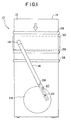
- FIG. 1 and FIG. 2 illustrate a top plan view and a cross-sectional side view, respectively, of one embodiment of the present tension arm developer apparatus for developing an imaging sheet 14 in accordance with the invention.
- the apparatus 10 comprises a tension arm 16 , a developer head 18 at the distal end of arm 16 containing a point contact element 36 which is in intimate contact with the surface 12 of the exposed imaging sheet 14 , a slot 20 at the proximal end of the arm 16 for engaging a pin 22 on cam 24 , a motor M for rotating the cam 24 , and a vertical axle 26 about which arm 16 pivots causing the arm 16 to oscillate back and forth so that the point contact element 36 provides a plurality of arcuate paths across the upper surface 12 of an exposed imaging sheet 14 .
- the point contact element 36 moves across a surface 12 of the exposed imaging sheet 14 in a plurality of arcuate paths which traverse substantially the entire image area of exposed imaging sheet 14 .
- the microcapsules are ruptured by pressure exerted on the exposed imaging sheet 14 by the point contact element 36 as the imaging sheet passes between the point contact element 36 and the developer plate 30 causing the internal phase to be released from the ruptured microcapsules where it reacts with the developer material to form a visible image.
- tension is exerted on the surface 12 of the exposed imaging sheet 14 by the point contact element 36 as a result of a downwardly resilient spring tension or torque in the tension arm 16 .
- the tension is applied by a compression means illustrated in FIGS. 3 and 5 as a compression spring member 32 placed between the point contact element 36 and the support member 34 for the point contact element.
- FIG. 3 shows in a cross-sectional illustration, the embodiment wherein the pressure exerted on the point contact element 36 is provided by a compression spring member 32 positioned in a sleeve 38 .
- the point contact element 36 is retained in a socket 40 of support member 34 .
- the support member 34 is slidingly retained in sleeve 38 by a retaining means 42 on sleeve 38 which fits into inset 44 so that the support 34 can move in a vertical direction and spring member 32 causes support 34 to be resiliently biased in a downwardly direction from arm 16 .
- pressure is exerted on the surface of the exposed imaging sheet 14 by the point contact element 36 as a result of resilient spring tension or torque in a flexible tension arm.
- the developer head 18 may be a simple housing connected to the arm 16 wherein the support 34 retains a point contact element 36 in a receiving socket 40 as illustrated in FIG. 4. Similar mountings are used in ballpoint pens. If additional pressure is desired, a compression spring member or compressed air can be exerted upon the point contact element 36 as shown in FIG. 3 in conjunction with the flexible tension arm.
- a pressure load to be applied to the point contact element 36 is dependent upon both the type of substrate upon which the point contact element 36 rolls and upon the diameter of the point contact element 36 itself. It has been found that a pressure load of up to about 1.36 kg (3 pounds) on the point contact is sufficient to carry out the present invention and a load of about 0.45 to 0.73 kg (1 to 1.6 pounds) is preferred if the diameter of the point contact element 36 is 6 mm (1/4 inch) and the substrate is a polyester film. If the diameter of the point contact element 36 is about 3 mm (1/8 inch) and the substrate is a polyester film, it is believed that the pressure load would decrease to about 0.23 kg (0.5 pounds).
- FIGS. 3, 4, and 5 are preferred for use in the present invention
- a solid device having a non-rotatable tip may be employed.
- multiple rotatable or non-rotatable point contact elements resiliently biased into contact with the surface of the exposed imaging sheet to provide multiple paths across the surface of the sheet.
- the multiple point contact elements are arranged so that each element provides a path which is parallel to and slightly off-set from the paths of adjacent elements. In this arrangement, the paths overlap to provide a much broader stripe for each oscillation of the element.
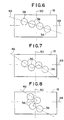
- FIG. 6 illustrates the arrangement of spherical point contact elements 36 in which the elements 36 are aligned in a linear line 46 which is slightly oblique with respect to the lateral axis 48 of the developer head 18 .
- the arrangement of point contact elements 36 is illustrated by non-linear lines 48 which are arranged in zigzag configurations along the lateral axis 48 and the longitudinal axis 50 of the developer head 16 , respectively.
- Other configurations are possible such as a circular arrangement of the point contact elements with respect to the applicator head.
- the point contact element which is preferred in the present invention is a bearing or ball which rotates freely in a receiving socket 40 where it provides a sufficient pressure to rupture the microcapsules in the imaging sheet.
- the point contact element is made from any hard material such as metal, e.g. steel, brass, etc. or ultra high molecular weight polymer, e.g., UHMW polyethylene. Particularly good results have been achieved using a point contact element made of brass.
- the size of the point contact element is not critical; however, it has been found that a preferred range of the ball size would be between about 0.78 mm (1/32 inch) and 12.5 mm (1/2 inch) while the most preferred diameter of the ball would be about 3 mm (1/8 inch).
- the spherical point contact element is free to rotate in any direction within the socket.
- the spherical point contact element 36 is supported on an axle 52 and is therefore limited to either forward or backward rotation.
- the pressure exerted in FIG. 5 is by a spring member, but such pressure could be provided by a pneumatic pressure system using air as the pressurizing agent, or the pressure may be provided by spring tension or torque such as that resulting from a flexible arm.
- the developer apparatus 10 In order for the developer apparatus 10 to be resiliently biased into simultaneous bi-directional engagement with the surface of the exposed imaging sheet, it is necessary to move either the imaging sheet or the developer apparatus in a longitudinal direction essentially perpendicular to the oscillation of the tension arm.
- it is the exposed imaging sheet 14 which is transported in accordance with the present invention, the direction of movement being in the direction of the arrow as shown in FIG. 1.
- the exposed imaging sheet 14 is moved across a developer plate 30 by rubber coated rollers 28 .
- the tension arm 16 is oscillated transversely by the rotating cam 24 .
- the movement of the spherical point contact element 36 across either the top surface or bottom surface of the exposed imaging sheet 14 creates a pressure stripe along the path of travel which causes development of a small section of the image corresponding to the pressure stripe.
- the tension arm 16 is moved in the opposite direction producing a pressure stripe which overlaps the previous stripe, preferably by about 10 to 30% and most preferably by about 18%.
- the exposed imaging sheet 14 can be moved across the developer plate 30 continuously or it can be moved in specific increments until the entire exposed imaging sheet is developed.
- the imaging sheet described above has been characterized as an exposed imaging sheet and it typically would be employed as such, however, the use of an exposed imaging sheet is not necessary in the practice of the invention.
Landscapes
- Physics & Mathematics (AREA)
- General Physics & Mathematics (AREA)
- Photographic Developing Apparatuses (AREA)
- Dry Development In Electrophotography (AREA)
- Dot-Matrix Printers And Others (AREA)
- Photographic Processing Devices Using Wet Methods (AREA)
- Photosensitive Polymer And Photoresist Processing (AREA)
- Printers Or Recording Devices Using Electromagnetic And Radiation Means (AREA)
- Coating Apparatus (AREA)
Claims (20)
- Appareil de développement par pression à utiliser pour le développement d'images dans la zone d'image d'une feuille photosensible de formation d'image (14) contenant des microcapsules, ledit appareil comprenant :une tête de développement (18) comprenant une pluralité d'éléments de contact ponctuel (36), lesdits éléments de contact ponctuel (36) étant sollicités en contact avec une surface de ladite feuille de formation d'image (14) ;un mécanisme d'entraínement couplé à ladite tête de développement (18) pour faire osciller ladite tête de développement (18) en travers de la surface de ladite feuille de formation d'image (14) ; etdes moyens pour établir un mouvement longitudinal entre ladite tête de développement (18) et ladite feuille de formation d'image (14),dans lequel ladite tête de développement (18) oscille en travers de la surface de ladite feuille de formation d'image (14) et lesdits éléments de contact ponctuel (36) appliquent une pression uniforme suffisante le long d'une pluralité de trajets en travers de la surface de ladite feuille de formation d'image (14) pour rompre lesdites microcapsules sensiblement dans toute la zone de formation d'image,ladite pluralité d'éléments de contact ponctuel (36) étant disposés de sorte que chaque élément (36) forme un trajet qui est parallèle et légèrement décalé par rapport aux trajets d'éléments adjacents (36).
- Appareil selon la revendication 1, dans lequel ladite pluralité d'éléments de contact ponctuel (36) sont disposés selon une ligne droite.
- Appareil selon la revendication 1, dans lequel ladite pluralité d'éléments de contact ponctuel (36) sont disposés selon une ligne non droite.
- Appareil de développement par pression selon l'une des revendications 1 à 3, comprenant un bras (16) monté pour osciller en travers de la surface (12) de ladite feuille de formation d'image (14),des moyens pour faire osciller ledit bras (16) en travers de la surface (12) de ladite feuille de formation d'image (14),des moyens pour établir un mouvement longitudinal entre ledit bras (16) et ladite feuille de formation d'image (14) ; et dans lequelladite tête de développement (18) est positionnée le long de l'axe dudit bras (16).
- Appareil selon la revendication 4, dans lequel lesdits moyens pour faire osciller ledit bras (16) en travers de la surface de ladite feuille de formation d'image (14) comprennent une came (24).
- Appareil selon la revendication 5, dans lequel ledit bras (16) est monté sur un moyen de pivotement perpendiculaire à la surface (12) de ladite feuille de formation d'image (14), ledit bras (16) comprenant une fente (20) à son extrémité proximale pour engager une pointe (22) sur ladite came (24).
- Appareil selon la revendication 5, dans lequel ladite tête de développement (18) est disposée vers l'extrémité distale dudit bras (16).
- Appareil selon l'une quelconque des précédentes revendications, dans lequel ladite tête de développement (18) peut se déplacer le long de l'axe dudit bras (16), le déplacement de ladite tête de développement (18) le long dudit axe étant synchronisé avec l'oscillation dudit bras (16) de sorte que lesdits éléments de contact ponctuel (36) appliquent une pression uniforme le long d'une pluralité de trajets linéaires.
- Appareil selon l'une quelconque des précédentes revendications, dans lequel chacun desdits éléments de contact ponctuel (36) est un élément sphérique ayant un diamètre d'environ 0,78 mm (1/32 pouce) à environ 12,5 mm (1/2 pouce), et ladite pression uniforme correspond à une charge d'environ 0,23 kg (O,5 livre) à environ 1,36 kg (3 livres).
- Appareil selon la revendication 4, dans lequel lesdits moyens pour faire osciller ledit bras (16) amènent un mouvement pivotant dudit bras (16) et un mouvement courbe de ladite tête de développement (18).
- Appareil selon la revendication 9, dans lequel ledit élément sphérique (36) est monté en vue d'une rotation dans une cavité de réception appropriée (40) située dans ladite tête de développement (18), de sorte qu'un contact ponctuel est établi par ledit élément sphérique (36) alors qu'il tourne à l'intérieur de ladite cavité et sur la surface de ladite feuille de formation d'image (14).
- Appareil selon la revendication 1, dans lequel ledit élément sphérique (36) a un diamètre de 3 mm (1/8 pouce).
- Appareil selon la revendication 12, dans lequel ladite pression uniforme correspond à une charge de 0,45 kg (1 livre) à 0,73 kg (1,6 livre) sur ledit contact ponctuel.
- Appareil selon l'une quelconque des précédentes revendications, dans lequel ledit bras (16) est monté par rapport à ladite feuille de formation d'image (14) de telle sorte qu'il y a une tension agissant vers le bas dans le bras (16) qui sollicite de manière élastique lesdits éléments de contact ponctuel (36) en contact continu avec la surface supérieure (12) de ladite feuille de formation d'image (14).
- Appareil selon l'une quelconque des précédentes revendications, dans lequel ladite tête de développement (18) comprend en outre un moyen de pression qui agit sur lesdits élément de contact ponctuel (36) et sollicite de manière élastique lesdits éléments de contact ponctuel (36) en contact continu avec la surface (12) de ladite feuille de formation d'image (14).
- Appareil selon la revendication 15, dans lequel ledit moyen de pression comprend un ressort de compression (32).
- Appareil selon la revendication 15, dans lequel ledit moyen de pression comprend une source de pression d'air.
- Appareil selon l'une quelconque des précédentes revendications, dans lequel ledit élément de contact ponctuel (36) est relié à ladite tête de développement (18) sur un axe.
- Appareil selon l'une quelconque des précédentes revendications, dans lequel ladite feuille de formation d'image (14) est déplacée par intermittence à la fin de chaque oscillation de ladite tête de développement (18) le long d'un trajet longitudinal linéaire perpendiculaire aux trajets formés par ledit élément de contact ponctuel (36) de sorte que lesdits éléments de contact ponctuel (36) sont sollicités de manière élastique en contact bidirectionnel simultané avec la surface (12) de ladite feuille de formation d'image (14) où une pression uniforme est appliquée sensiblement à toute la zone d'image.
- Appareil selon la revendication 19, dans lequel lesdits trajets se chevauchent.
Applications Claiming Priority (3)
| Application Number | Priority Date | Filing Date | Title |
|---|---|---|---|
| US08/380,385 US5546154A (en) | 1995-01-30 | 1995-01-30 | Pressure developer apparatus |
| US380385 | 1995-01-30 | ||
| PCT/US1996/000979 WO1996024089A1 (fr) | 1995-01-30 | 1996-01-29 | Appareil de developpement avec un bras appliquant une pression |
Publications (2)
| Publication Number | Publication Date |
|---|---|
| EP0807280A1 EP0807280A1 (fr) | 1997-11-19 |
| EP0807280B1 true EP0807280B1 (fr) | 2001-04-18 |
Family
ID=23500971
Family Applications (1)
| Application Number | Title | Priority Date | Filing Date |
|---|---|---|---|
| EP96905210A Expired - Lifetime EP0807280B1 (fr) | 1995-01-30 | 1996-01-29 | Appareil de developpement par pression |
Country Status (14)
| Country | Link |
|---|---|
| US (1) | US5546154A (fr) |
| EP (1) | EP0807280B1 (fr) |
| JP (1) | JPH10513274A (fr) |
| KR (1) | KR19980701773A (fr) |
| CN (1) | CN1083582C (fr) |
| AT (1) | ATE200713T1 (fr) |
| AU (1) | AU4902796A (fr) |
| DE (1) | DE69612547T2 (fr) |
| IL (1) | IL116950A (fr) |
| IN (1) | IN188353B (fr) |
| MY (1) | MY120876A (fr) |
| TW (1) | TW452673B (fr) |
| WO (1) | WO1996024089A1 (fr) |
| ZA (1) | ZA96655B (fr) |
Families Citing this family (6)
| Publication number | Priority date | Publication date | Assignee | Title |
|---|---|---|---|---|
| US6483575B1 (en) | 2000-06-19 | 2002-11-19 | Eastman Kodak Company | Image forming device and method for processing photosensitive media having microencapsulated imaging material |
| US6390694B1 (en) | 2000-06-19 | 2002-05-21 | Eastman Kodak Company | Imaging assembly and media cartridge having cooperating linkage arrangements |
| US6268094B1 (en) | 2000-06-19 | 2001-07-31 | Eastman Kodak Company | Photosensitive media cartridge having an ambient condition sensor |
| US20050275823A1 (en) * | 2004-06-11 | 2005-12-15 | Camp Alphonse D | Photosensitive media cassette for an imaging device |
| EP3616029B1 (fr) | 2017-04-29 | 2022-11-30 | Luitpold Greiner | Affichage tactile à actionneur linéaire axisymétrique magnétique bistable pourvu de contour de pôle et matrice de commutation et aide visuelle optique tactile correspondante |
| WO2025172823A1 (fr) | 2024-02-12 | 2025-08-21 | Polaroid Ip B.V. | Dispositifs d'imagerie améliorés, appareil et procédés de développement de supports d'enregistrement d'image |
Family Cites Families (5)
| Publication number | Priority date | Publication date | Assignee | Title |
|---|---|---|---|---|
| US4648699A (en) * | 1985-10-31 | 1987-03-10 | The Mead Corporation | Point contact development of imaging sheets employing photosensitive microcapsules |
| US4872032A (en) * | 1987-02-18 | 1989-10-03 | Brother Kogyokabushiki Kaisha | Image fixing device |
| JPS63157745U (fr) * | 1987-04-01 | 1988-10-17 | ||
| JPH01113751A (ja) * | 1987-10-27 | 1989-05-02 | Sony Corp | 現像装置 |
| US4914463A (en) * | 1987-11-14 | 1990-04-03 | Sony Corp. | Development of imaging sheets employing photosensitive microcapsules |
-
1995
- 1995-01-30 US US08/380,385 patent/US5546154A/en not_active Expired - Fee Related
-
1996
- 1996-01-29 WO PCT/US1996/000979 patent/WO1996024089A1/fr not_active Ceased
- 1996-01-29 JP JP8523619A patent/JPH10513274A/ja active Pending
- 1996-01-29 EP EP96905210A patent/EP0807280B1/fr not_active Expired - Lifetime
- 1996-01-29 ZA ZA96655A patent/ZA96655B/xx unknown
- 1996-01-29 CN CN96191676A patent/CN1083582C/zh not_active Expired - Fee Related
- 1996-01-29 IL IL11695096A patent/IL116950A/xx not_active IP Right Cessation
- 1996-01-29 KR KR1019970705169A patent/KR19980701773A/ko not_active Withdrawn
- 1996-01-29 AU AU49027/96A patent/AU4902796A/en not_active Abandoned
- 1996-01-29 DE DE69612547T patent/DE69612547T2/de not_active Expired - Fee Related
- 1996-01-29 AT AT96905210T patent/ATE200713T1/de not_active IP Right Cessation
- 1996-01-30 IN IN154CA1996 patent/IN188353B/en unknown
- 1996-01-30 MY MYPI96000344A patent/MY120876A/en unknown
- 1996-03-01 TW TW085102452A patent/TW452673B/zh active
Also Published As
| Publication number | Publication date |
|---|---|
| IL116950A (en) | 1999-12-31 |
| DE69612547T2 (de) | 2001-08-09 |
| ATE200713T1 (de) | 2001-05-15 |
| IL116950A0 (en) | 1996-05-14 |
| IN188353B (fr) | 2002-09-14 |
| CN1172537A (zh) | 1998-02-04 |
| EP0807280A1 (fr) | 1997-11-19 |
| KR19980701773A (ko) | 1998-06-25 |
| CN1083582C (zh) | 2002-04-24 |
| US5546154A (en) | 1996-08-13 |
| TW452673B (en) | 2001-09-01 |
| WO1996024089A1 (fr) | 1996-08-08 |
| MY120876A (en) | 2005-12-30 |
| DE69612547D1 (de) | 2001-05-23 |
| JPH10513274A (ja) | 1998-12-15 |
| ZA96655B (en) | 1996-07-16 |
| AU4902796A (en) | 1996-08-21 |
Similar Documents
| Publication | Publication Date | Title |
|---|---|---|
| US4648699A (en) | Point contact development of imaging sheets employing photosensitive microcapsules | |
| US4727392A (en) | Pressure development apparatus for imaging sheets employing photosensitive microcapsules | |
| GB2290747B (en) | Apparatus and method for rotary bonding | |
| KR19990067630A (ko) | 엔드리스 벨트를 조정하기 위한 장치 및 방법 | |
| EP0807280B1 (fr) | Appareil de developpement par pression | |
| US4864343A (en) | Pressure development roll for imaging sheets employing photosensitive microcapsules | |
| US4235166A (en) | Fixing apparatus | |
| US4127066A (en) | Adjustable compression roller apparatus | |
| JPS61235836A (ja) | 感光性マイクロカプセルを用いた画像形成用シートの磁気ブラシ摩食現像 | |
| JPH07287462A (ja) | 定着装置 | |
| US4135475A (en) | Apparatus for applying liquid to sheetlike material | |
| JPS6048061A (ja) | ト−ニング方法および装置 | |
| CA2185601A1 (fr) | Systeme de gestion d'agent anti-adhesion a rouleau distributeur a configuration discontinue | |
| JPS63273862A (ja) | 圧力現像装置 | |
| DE2938800A1 (de) | Tragvorrichtung fuer ein band und elektrophotographische reproduktionsmaschine mit einem solchen band | |
| US4901103A (en) | Image recording apparatus using pressure sensitive sheet | |
| US4824755A (en) | Pressure roller developed images via pre-abrasion | |
| GB2172123A (en) | Rupturing photosensitive microcapsules in developing latent images | |
| US4872032A (en) | Image fixing device | |
| JPH02178074A (ja) | 熱転写プリンタ | |
| JPH0272352A (ja) | 圧力ローラ装置 | |
| JPH04204783A (ja) | 記録装置 | |
| JPS6091379A (ja) | 圧力定着装置 | |
| JPH05333613A (ja) | 圧力解除機構 | |
| KR100234327B1 (ko) | 레이저 프린터의 감광 벨트 접지장치 |
Legal Events
| Date | Code | Title | Description |
|---|---|---|---|
| PUAI | Public reference made under article 153(3) epc to a published international application that has entered the european phase |
Free format text: ORIGINAL CODE: 0009012 |
|
| 17P | Request for examination filed |
Effective date: 19970710 |
|
| AK | Designated contracting states |
Kind code of ref document: A1 Designated state(s): AT BE CH DE DK ES FR GB GR IE IT LI LU MC NL PT SE |
|
| RAP1 | Party data changed (applicant data changed or rights of an application transferred) |
Owner name: CYCOLOR, INC. |
|
| 17Q | First examination report despatched |
Effective date: 19981203 |
|
| RTI1 | Title (correction) |
Free format text: PRESSURE DEVELOPER APPARATUS |
|
| GRAG | Despatch of communication of intention to grant |
Free format text: ORIGINAL CODE: EPIDOS AGRA |
|
| GRAG | Despatch of communication of intention to grant |
Free format text: ORIGINAL CODE: EPIDOS AGRA |
|
| GRAH | Despatch of communication of intention to grant a patent |
Free format text: ORIGINAL CODE: EPIDOS IGRA |
|
| GRAH | Despatch of communication of intention to grant a patent |
Free format text: ORIGINAL CODE: EPIDOS IGRA |
|
| ITF | It: translation for a ep patent filed | ||
| GRAA | (expected) grant |
Free format text: ORIGINAL CODE: 0009210 |
|
| AK | Designated contracting states |
Kind code of ref document: B1 Designated state(s): AT BE CH DE DK ES FR GB GR IE IT LI LU MC NL PT SE |
|
| PG25 | Lapsed in a contracting state [announced via postgrant information from national office to epo] |
Ref country code: NL Free format text: LAPSE BECAUSE OF FAILURE TO SUBMIT A TRANSLATION OF THE DESCRIPTION OR TO PAY THE FEE WITHIN THE PRESCRIBED TIME-LIMIT Effective date: 20010418 Ref country code: LI Free format text: LAPSE BECAUSE OF FAILURE TO SUBMIT A TRANSLATION OF THE DESCRIPTION OR TO PAY THE FEE WITHIN THE PRESCRIBED TIME-LIMIT Effective date: 20010418 Ref country code: CH Free format text: LAPSE BECAUSE OF FAILURE TO SUBMIT A TRANSLATION OF THE DESCRIPTION OR TO PAY THE FEE WITHIN THE PRESCRIBED TIME-LIMIT Effective date: 20010418 Ref country code: BE Free format text: LAPSE BECAUSE OF FAILURE TO SUBMIT A TRANSLATION OF THE DESCRIPTION OR TO PAY THE FEE WITHIN THE PRESCRIBED TIME-LIMIT Effective date: 20010418 Ref country code: AT Free format text: LAPSE BECAUSE OF FAILURE TO SUBMIT A TRANSLATION OF THE DESCRIPTION OR TO PAY THE FEE WITHIN THE PRESCRIBED TIME-LIMIT Effective date: 20010418 |
|
| REF | Corresponds to: |
Ref document number: 200713 Country of ref document: AT Date of ref document: 20010515 Kind code of ref document: T |
|
| REG | Reference to a national code |
Ref country code: CH Ref legal event code: EP |
|
| REF | Corresponds to: |
Ref document number: 69612547 Country of ref document: DE Date of ref document: 20010523 |
|
| ET | Fr: translation filed | ||
| REG | Reference to a national code |
Ref country code: IE Ref legal event code: FG4D |
|
| PG25 | Lapsed in a contracting state [announced via postgrant information from national office to epo] |
Ref country code: SE Free format text: LAPSE BECAUSE OF FAILURE TO SUBMIT A TRANSLATION OF THE DESCRIPTION OR TO PAY THE FEE WITHIN THE PRESCRIBED TIME-LIMIT Effective date: 20010718 Ref country code: PT Free format text: LAPSE BECAUSE OF FAILURE TO SUBMIT A TRANSLATION OF THE DESCRIPTION OR TO PAY THE FEE WITHIN THE PRESCRIBED TIME-LIMIT Effective date: 20010718 Ref country code: DK Free format text: LAPSE BECAUSE OF FAILURE TO SUBMIT A TRANSLATION OF THE DESCRIPTION OR TO PAY THE FEE WITHIN THE PRESCRIBED TIME-LIMIT Effective date: 20010718 |
|
| PG25 | Lapsed in a contracting state [announced via postgrant information from national office to epo] |
Ref country code: GR Free format text: LAPSE BECAUSE OF FAILURE TO SUBMIT A TRANSLATION OF THE DESCRIPTION OR TO PAY THE FEE WITHIN THE PRESCRIBED TIME-LIMIT Effective date: 20010720 |
|
| NLV1 | Nl: lapsed or annulled due to failure to fulfill the requirements of art. 29p and 29m of the patents act | ||
| PG25 | Lapsed in a contracting state [announced via postgrant information from national office to epo] |
Ref country code: ES Free format text: LAPSE BECAUSE OF FAILURE TO SUBMIT A TRANSLATION OF THE DESCRIPTION OR TO PAY THE FEE WITHIN THE PRESCRIBED TIME-LIMIT Effective date: 20011030 |
|
| REG | Reference to a national code |
Ref country code: CH Ref legal event code: PL |
|
| REG | Reference to a national code |
Ref country code: GB Ref legal event code: IF02 |
|
| PG25 | Lapsed in a contracting state [announced via postgrant information from national office to epo] |
Ref country code: LU Free format text: LAPSE BECAUSE OF NON-PAYMENT OF DUE FEES Effective date: 20020129 Ref country code: IE Free format text: LAPSE BECAUSE OF NON-PAYMENT OF DUE FEES Effective date: 20020129 |
|
| PLBE | No opposition filed within time limit |
Free format text: ORIGINAL CODE: 0009261 |
|
| STAA | Information on the status of an ep patent application or granted ep patent |
Free format text: STATUS: NO OPPOSITION FILED WITHIN TIME LIMIT |
|
| 26N | No opposition filed | ||
| PG25 | Lapsed in a contracting state [announced via postgrant information from national office to epo] |
Ref country code: MC Free format text: LAPSE BECAUSE OF NON-PAYMENT OF DUE FEES Effective date: 20020801 |
|
| REG | Reference to a national code |
Ref country code: IE Ref legal event code: MM4A |
|
| REG | Reference to a national code |
Ref country code: GB Ref legal event code: 732E |
|
| REG | Reference to a national code |
Ref country code: FR Ref legal event code: TP |
|
| PGFP | Annual fee paid to national office [announced via postgrant information from national office to epo] |
Ref country code: IT Payment date: 20060131 Year of fee payment: 11 |
|
| PGFP | Annual fee paid to national office [announced via postgrant information from national office to epo] |
Ref country code: GB Payment date: 20070125 Year of fee payment: 12 |
|
| PGFP | Annual fee paid to national office [announced via postgrant information from national office to epo] |
Ref country code: DE Payment date: 20070228 Year of fee payment: 12 |
|
| PGFP | Annual fee paid to national office [announced via postgrant information from national office to epo] |
Ref country code: FR Payment date: 20070117 Year of fee payment: 12 |
|
| GBPC | Gb: european patent ceased through non-payment of renewal fee |
Effective date: 20080129 |
|
| PG25 | Lapsed in a contracting state [announced via postgrant information from national office to epo] |
Ref country code: DE Free format text: LAPSE BECAUSE OF NON-PAYMENT OF DUE FEES Effective date: 20080801 |
|
| REG | Reference to a national code |
Ref country code: FR Ref legal event code: ST Effective date: 20081029 |
|
| PG25 | Lapsed in a contracting state [announced via postgrant information from national office to epo] |
Ref country code: GB Free format text: LAPSE BECAUSE OF NON-PAYMENT OF DUE FEES Effective date: 20080129 |
|
| PG25 | Lapsed in a contracting state [announced via postgrant information from national office to epo] |
Ref country code: FR Free format text: LAPSE BECAUSE OF NON-PAYMENT OF DUE FEES Effective date: 20080131 |
|
| PG25 | Lapsed in a contracting state [announced via postgrant information from national office to epo] |
Ref country code: IT Free format text: LAPSE BECAUSE OF NON-PAYMENT OF DUE FEES Effective date: 20070129 |