EP0806768A2 - Aufzeichnungsträger, Vorrichtung zur optischen Wiedergabe von Information sowie Suchmethode - Google Patents
Aufzeichnungsträger, Vorrichtung zur optischen Wiedergabe von Information sowie Suchmethode Download PDFInfo
- Publication number
- EP0806768A2 EP0806768A2 EP97107472A EP97107472A EP0806768A2 EP 0806768 A2 EP0806768 A2 EP 0806768A2 EP 97107472 A EP97107472 A EP 97107472A EP 97107472 A EP97107472 A EP 97107472A EP 0806768 A2 EP0806768 A2 EP 0806768A2
- Authority
- EP
- European Patent Office
- Prior art keywords
- recording medium
- laser beam
- reproducing
- pits
- optical head
- Prior art date
- Legal status (The legal status is an assumption and is not a legal conclusion. Google has not performed a legal analysis and makes no representation as to the accuracy of the status listed.)
- Granted
Links
Images


Classifications
-
- G—PHYSICS
- G11—INFORMATION STORAGE
- G11B—INFORMATION STORAGE BASED ON RELATIVE MOVEMENT BETWEEN RECORD CARRIER AND TRANSDUCER
- G11B23/00—Record carriers not specific to the method of recording or reproducing; Accessories, e.g. containers, specially adapted for co-operation with the recording or reproducing apparatus ; Intermediate mediums; Apparatus or processes specially adapted for their manufacture
- G11B23/28—Indicating or preventing prior or unauthorised use, e.g. cassettes with sealing or locking means, write-protect devices for discs
- G11B23/281—Indicating or preventing prior or unauthorised use, e.g. cassettes with sealing or locking means, write-protect devices for discs by changing the physical properties of the record carrier
-
- G—PHYSICS
- G11—INFORMATION STORAGE
- G11B—INFORMATION STORAGE BASED ON RELATIVE MOVEMENT BETWEEN RECORD CARRIER AND TRANSDUCER
- G11B19/00—Driving, starting, stopping record carriers not specifically of filamentary or web form, or of supports therefor; Control thereof; Control of operating function ; Driving both disc and head
- G11B19/02—Control of operating function, e.g. switching from recording to reproducing
- G11B19/12—Control of operating function, e.g. switching from recording to reproducing by sensing distinguishing features of or on records, e.g. diameter end mark
- G11B19/122—Control of operating function, e.g. switching from recording to reproducing by sensing distinguishing features of or on records, e.g. diameter end mark involving the detection of an identification or authentication mark
-
- G—PHYSICS
- G11—INFORMATION STORAGE
- G11B—INFORMATION STORAGE BASED ON RELATIVE MOVEMENT BETWEEN RECORD CARRIER AND TRANSDUCER
- G11B23/00—Record carriers not specific to the method of recording or reproducing; Accessories, e.g. containers, specially adapted for co-operation with the recording or reproducing apparatus ; Intermediate mediums; Apparatus or processes specially adapted for their manufacture
- G11B23/28—Indicating or preventing prior or unauthorised use, e.g. cassettes with sealing or locking means, write-protect devices for discs
- G11B23/281—Indicating or preventing prior or unauthorised use, e.g. cassettes with sealing or locking means, write-protect devices for discs by changing the physical properties of the record carrier
- G11B23/282—Limited play
-
- G—PHYSICS
- G11—INFORMATION STORAGE
- G11B—INFORMATION STORAGE BASED ON RELATIVE MOVEMENT BETWEEN RECORD CARRIER AND TRANSDUCER
- G11B23/00—Record carriers not specific to the method of recording or reproducing; Accessories, e.g. containers, specially adapted for co-operation with the recording or reproducing apparatus ; Intermediate mediums; Apparatus or processes specially adapted for their manufacture
- G11B23/28—Indicating or preventing prior or unauthorised use, e.g. cassettes with sealing or locking means, write-protect devices for discs
- G11B23/283—Security features, e.g. digital codes
- G11B23/284—Security features, e.g. digital codes on the record carrier
-
- G—PHYSICS
- G11—INFORMATION STORAGE
- G11B—INFORMATION STORAGE BASED ON RELATIVE MOVEMENT BETWEEN RECORD CARRIER AND TRANSDUCER
- G11B7/00—Recording or reproducing by optical means, e.g. recording using a thermal beam of optical radiation by modifying optical properties or the physical structure, reproducing using an optical beam at lower power by sensing optical properties; Record carriers therefor
- G11B7/007—Arrangement of the information on the record carrier, e.g. form of tracks, actual track shape, e.g. wobbled, or cross-section, e.g. v-shaped; Sequential information structures, e.g. sectoring or header formats within a track
- G11B7/00745—Sectoring or header formats within a track
-
- G—PHYSICS
- G11—INFORMATION STORAGE
- G11B—INFORMATION STORAGE BASED ON RELATIVE MOVEMENT BETWEEN RECORD CARRIER AND TRANSDUCER
- G11B7/00—Recording or reproducing by optical means, e.g. recording using a thermal beam of optical radiation by modifying optical properties or the physical structure, reproducing using an optical beam at lower power by sensing optical properties; Record carriers therefor
- G11B7/12—Heads, e.g. forming of the optical beam spot or modulation of the optical beam
- G11B7/125—Optical beam sources therefor, e.g. laser control circuitry specially adapted for optical storage devices; Modulators, e.g. means for controlling the size or intensity of optical spots or optical traces
- G11B7/126—Circuits, methods or arrangements for laser control or stabilisation
-
- G—PHYSICS
- G11—INFORMATION STORAGE
- G11B—INFORMATION STORAGE BASED ON RELATIVE MOVEMENT BETWEEN RECORD CARRIER AND TRANSDUCER
- G11B7/00—Recording or reproducing by optical means, e.g. recording using a thermal beam of optical radiation by modifying optical properties or the physical structure, reproducing using an optical beam at lower power by sensing optical properties; Record carriers therefor
- G11B7/24—Record carriers characterised by shape, structure or physical properties, or by the selection of the material
- G11B7/2407—Tracks or pits; Shape, structure or physical properties thereof
- G11B7/24085—Pits
-
- G—PHYSICS
- G11—INFORMATION STORAGE
- G11B—INFORMATION STORAGE BASED ON RELATIVE MOVEMENT BETWEEN RECORD CARRIER AND TRANSDUCER
- G11B7/00—Recording or reproducing by optical means, e.g. recording using a thermal beam of optical radiation by modifying optical properties or the physical structure, reproducing using an optical beam at lower power by sensing optical properties; Record carriers therefor
- G11B7/24—Record carriers characterised by shape, structure or physical properties, or by the selection of the material
- G11B7/241—Record carriers characterised by shape, structure or physical properties, or by the selection of the material characterised by the selection of the material
- G11B7/242—Record carriers characterised by shape, structure or physical properties, or by the selection of the material characterised by the selection of the material of recording layers
- G11B7/243—Record carriers characterised by shape, structure or physical properties, or by the selection of the material characterised by the selection of the material of recording layers comprising inorganic materials only, e.g. ablative layers
-
- G—PHYSICS
- G11—INFORMATION STORAGE
- G11B—INFORMATION STORAGE BASED ON RELATIVE MOVEMENT BETWEEN RECORD CARRIER AND TRANSDUCER
- G11B7/00—Recording or reproducing by optical means, e.g. recording using a thermal beam of optical radiation by modifying optical properties or the physical structure, reproducing using an optical beam at lower power by sensing optical properties; Record carriers therefor
- G11B7/24—Record carriers characterised by shape, structure or physical properties, or by the selection of the material
- G11B7/241—Record carriers characterised by shape, structure or physical properties, or by the selection of the material characterised by the selection of the material
- G11B7/252—Record carriers characterised by shape, structure or physical properties, or by the selection of the material characterised by the selection of the material of layers other than recording layers
- G11B7/257—Record carriers characterised by shape, structure or physical properties, or by the selection of the material characterised by the selection of the material of layers other than recording layers of layers having properties involved in recording or reproduction, e.g. optical interference layers or sensitising layers or dielectric layers, which are protecting the recording layers
-
- G—PHYSICS
- G11—INFORMATION STORAGE
- G11B—INFORMATION STORAGE BASED ON RELATIVE MOVEMENT BETWEEN RECORD CARRIER AND TRANSDUCER
- G11B20/00—Signal processing not specific to the method of recording or reproducing; Circuits therefor
- G11B20/00086—Circuits for prevention of unauthorised reproduction or copying, e.g. piracy
-
- G—PHYSICS
- G11—INFORMATION STORAGE
- G11B—INFORMATION STORAGE BASED ON RELATIVE MOVEMENT BETWEEN RECORD CARRIER AND TRANSDUCER
- G11B7/00—Recording or reproducing by optical means, e.g. recording using a thermal beam of optical radiation by modifying optical properties or the physical structure, reproducing using an optical beam at lower power by sensing optical properties; Record carriers therefor
- G11B7/24—Record carriers characterised by shape, structure or physical properties, or by the selection of the material
- G11B7/241—Record carriers characterised by shape, structure or physical properties, or by the selection of the material characterised by the selection of the material
- G11B7/242—Record carriers characterised by shape, structure or physical properties, or by the selection of the material characterised by the selection of the material of recording layers
- G11B7/243—Record carriers characterised by shape, structure or physical properties, or by the selection of the material characterised by the selection of the material of recording layers comprising inorganic materials only, e.g. ablative layers
- G11B2007/24302—Metals or metalloids
- G11B2007/24314—Metals or metalloids group 15 elements (e.g. Sb, Bi)
-
- G—PHYSICS
- G11—INFORMATION STORAGE
- G11B—INFORMATION STORAGE BASED ON RELATIVE MOVEMENT BETWEEN RECORD CARRIER AND TRANSDUCER
- G11B7/00—Recording or reproducing by optical means, e.g. recording using a thermal beam of optical radiation by modifying optical properties or the physical structure, reproducing using an optical beam at lower power by sensing optical properties; Record carriers therefor
- G11B7/24—Record carriers characterised by shape, structure or physical properties, or by the selection of the material
- G11B7/241—Record carriers characterised by shape, structure or physical properties, or by the selection of the material characterised by the selection of the material
- G11B7/242—Record carriers characterised by shape, structure or physical properties, or by the selection of the material characterised by the selection of the material of recording layers
- G11B7/243—Record carriers characterised by shape, structure or physical properties, or by the selection of the material characterised by the selection of the material of recording layers comprising inorganic materials only, e.g. ablative layers
- G11B2007/24302—Metals or metalloids
- G11B2007/24316—Metals or metalloids group 16 elements (i.e. chalcogenides, Se, Te)
-
- G—PHYSICS
- G11—INFORMATION STORAGE
- G11B—INFORMATION STORAGE BASED ON RELATIVE MOVEMENT BETWEEN RECORD CARRIER AND TRANSDUCER
- G11B7/00—Recording or reproducing by optical means, e.g. recording using a thermal beam of optical radiation by modifying optical properties or the physical structure, reproducing using an optical beam at lower power by sensing optical properties; Record carriers therefor
- G11B7/004—Recording, reproducing or erasing methods; Read, write or erase circuits therefor
- G11B7/0045—Recording
- G11B7/00455—Recording involving reflectivity, absorption or colour changes
-
- G—PHYSICS
- G11—INFORMATION STORAGE
- G11B—INFORMATION STORAGE BASED ON RELATIVE MOVEMENT BETWEEN RECORD CARRIER AND TRANSDUCER
- G11B7/00—Recording or reproducing by optical means, e.g. recording using a thermal beam of optical radiation by modifying optical properties or the physical structure, reproducing using an optical beam at lower power by sensing optical properties; Record carriers therefor
- G11B7/08—Disposition or mounting of heads or light sources relatively to record carriers
- G11B7/085—Disposition or mounting of heads or light sources relatively to record carriers with provision for moving the light beam into, or out of, its operative position or across tracks, otherwise than during the transducing operation, e.g. for adjustment or preliminary positioning or track change or selection
- G11B7/08505—Methods for track change, selection or preliminary positioning by moving the head
-
- G—PHYSICS
- G11—INFORMATION STORAGE
- G11B—INFORMATION STORAGE BASED ON RELATIVE MOVEMENT BETWEEN RECORD CARRIER AND TRANSDUCER
- G11B7/00—Recording or reproducing by optical means, e.g. recording using a thermal beam of optical radiation by modifying optical properties or the physical structure, reproducing using an optical beam at lower power by sensing optical properties; Record carriers therefor
- G11B7/24—Record carriers characterised by shape, structure or physical properties, or by the selection of the material
- G11B7/241—Record carriers characterised by shape, structure or physical properties, or by the selection of the material characterised by the selection of the material
- G11B7/252—Record carriers characterised by shape, structure or physical properties, or by the selection of the material characterised by the selection of the material of layers other than recording layers
- G11B7/253—Record carriers characterised by shape, structure or physical properties, or by the selection of the material characterised by the selection of the material of layers other than recording layers of substrates
- G11B7/2533—Record carriers characterised by shape, structure or physical properties, or by the selection of the material characterised by the selection of the material of layers other than recording layers of substrates comprising resins
- G11B7/2534—Record carriers characterised by shape, structure or physical properties, or by the selection of the material characterised by the selection of the material of layers other than recording layers of substrates comprising resins polycarbonates [PC]
-
- G—PHYSICS
- G11—INFORMATION STORAGE
- G11B—INFORMATION STORAGE BASED ON RELATIVE MOVEMENT BETWEEN RECORD CARRIER AND TRANSDUCER
- G11B7/00—Recording or reproducing by optical means, e.g. recording using a thermal beam of optical radiation by modifying optical properties or the physical structure, reproducing using an optical beam at lower power by sensing optical properties; Record carriers therefor
- G11B7/24—Record carriers characterised by shape, structure or physical properties, or by the selection of the material
- G11B7/241—Record carriers characterised by shape, structure or physical properties, or by the selection of the material characterised by the selection of the material
- G11B7/252—Record carriers characterised by shape, structure or physical properties, or by the selection of the material characterised by the selection of the material of layers other than recording layers
- G11B7/258—Record carriers characterised by shape, structure or physical properties, or by the selection of the material characterised by the selection of the material of layers other than recording layers of reflective layers
- G11B7/2585—Record carriers characterised by shape, structure or physical properties, or by the selection of the material characterised by the selection of the material of layers other than recording layers of reflective layers based on aluminium
Definitions
- This invention relates to a recording medium capable of reproducing recorded information optically, an optical information reproducing apparatus for reproducing recorded information stored in the recording medium and a seek method using the optical information reproducing apparatus.
- optical disks which are recording media capable of optically reproducing recording data.
- MO disk magnetic optical disks
- MD mini-disk: trade mark
- phase change type optical disk and the like As a disk capable of recording only once, write once read many (WOR) disk is available and as a optical disk designed for read only, so-called CD-ROM and the like are currently marketed.
- WOR write once read many
- a number of rewrites is for example about 10 6 times and a number of reproduction is for example about 10 9 times.
- a number of recording is only one and a number of reproduction is for example about 10 9 times.
- a number of recording is one and a number of reproduction is theoretically unlimited.
- All the aforementioned various optical disks contain a problem relating to copy right. That is, even if for example recorded data is processed with scramble or the like for only users having an appropriate privilege of use in viewpoints of copy right so as to resolve the scramble and reproduce the recorded data, if anyone obtains a means for resolving that scramble, he can pick up the recorded data freely even if he is not a person having an appropriate privilege in terms of copy right.
- optical disks permitted to be for example rented there is necessary to collect these optical disks if an appropriate term is passed. That is, although a user having a permission to rent an optical disk can be said to be a proper privileged person for use of that optical disk within a rental period, if that rental period is passed, he loses his privilege for proper use. Thus, that optical disk must be collected. Further, there is a case in which an appropriate optical disk is not desired to be rented for the reason of copy right.
- an object of the present invention is to provide a recording medium which is capable of reducing problems relating to copy right and if the recording medium is an optical disk permitted to be used for rental, reducing a necessity of collecting that optical disk, and further enabling the optical disk itself to be inhibited from rental use.
- a recording medium having pits in which information is reproduced by irradiating beam on the pits, the recording medium further containing reproducing films for generating the pits in which reflectance thereof is changed by irradiating a laser beam having a higher strength than a predetermined value.
- a recording medium according to claim 1 wherein the reflectance of the reproducing film drops when a laser beam having a higher strength than the predetermined value is irradiated.
- a recording medium according to claim 2 further comprising address sections for recording address information and data information sections for recording data information by means of the pits.
- a recording medium according to claim 3 wherein the data information sections are generated by the pits and depth of the pits is between ⁇ /8 + n ⁇ /2 and ⁇ /6 + n ⁇ /2 (n is an integer except 0) assuming a wavelength of the laser beam to be 1.
- a recording medium according to claim 3 wherein the address information sections are generated by the pits and depth of the pits is between substantially ⁇ /4 + ⁇ /2 (n is an integer except 0) assuming a wavelength of the laser beam to be 1.
- a recording medium according to claim 4 further comprising a groove at least on one side of both sides of the pit in laser beam scanning direction, the address information sections being formed by forming the grooves in wobbling shape.
- a recording medium according to claim 4 further comprising grooves on both sides of the pit in laser beam scanning direction, the grooves being substantially ⁇ /8 in depth assuming the wavelength of the laser beam to be 1.
- a recording medium according to claim 4 wherein the address information sections are formed by wobbling the pits.
- a recording medium according to claim 1 wherein the reproducing film includes a first layer made of Sb2Se3, a second layer made of Bi2Te3 and a third layer made of Sb2Se3 and when laser beam is irradiated on the reproducing film, the first layer, the second layer and the third layer are melted, mixed and alloyed so as to change reflectance.
- a recording medium according to claim 3 wherein the address information sections and the data information sections are formed by the pits and a spatial frequency in which the pit in the address information section is read out by the laser beam is set to be lower than a spatial frequency in which the pit in the data information section is read out by the laser beam.
- a recording medium according to claim 1 further comprising another reproducing film whose reflectance is changed if a laser beam having a higher strength than the predetermined value is irradiated, the another reproducing film being formed on a side opposite to the side having the reproducing film.
- a recording medium reproducing apparatus for reading information optically from a recording medium, comprising: an optical head for irradiating optical beam on the recording medium; a light detecting means for receiving light reflected from the recording medium and outputting a detecting signal; a demodulating means for demodulating the detecting signal and outputting a demodulated signal; an error correcting means for detecting errors in the demodulated data signal, correcting the error and outputting reproduced data signals; and a reproducing beam power control means for controlling beam power of reproducing light beam to be irradiated from the optical head.
- a recording medium reproducing apparatus further comprising a seek means for seeking the optical head at a desired position, the reproducing beam power control means controlling so as to irradiate light beam from the optical head at a first laser power at the time of ordinary reproduction and controlling during seek operation so as to irradiate the light beam from the optical head at a second laser power which is smaller than the first laser power.
- a method for seeking said optical head at a desired position on the recording medium comprising: a light beam irradiating process for irradiating light beam from the optical head to the recording medium; a light detecting process for receiving a light reflected from the recording medium and outputting detecting signals; a demodulating process for demodulating the detecting signals and outputting demodulation data signals; an error correcting process for detecting errors in the demodulation data signals, correcting the errors and outputting reproduced data signals; a seek process for seeking the optical head at a desired position on the recording medium; a first control process for controlling so as to irradiate light beam from the optical head at a first laser power at the time of ordinary reproduction; and a control process for controlling during seek operation so as to irradiate light beam from the optical head at a second laser power which is smaller than the first laser power.
- Fig. 1 is a perspective view of an optical disk according to the present invention.
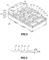
- Fig. 2 is an enlarged perspective view partially broken of the optical disk shown in Fig. 1.
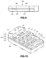
- Fig. 3 is a diagram for explaining a relation between a groove and a pit of an optical disk according to the present invention.
- Fig. 4 is a sectional view showing a configuration of a reproducing film of the optical disk according to the present invention.
- Fig. 5 is a diagram for explaining a relation between the depth of a pit or groove in the optical disk and degrees of modulation before and after irradiation of laser beam according to the present invention.
- Fig. 6 is a diagram for explaining the spatial frequency of a pit in the address section and the spatial frequency of a pit in the data section.
- Fig. 7 is a diagram showing a relation between the spatial frequency of the address section and the spatial frequency of the data section and amplitude.
- Fig. 8 is a waveform diagram for explaining reproduced signal waveforms in the address section and data section before and after irradiation of laser beam and levels thereof.
- Fig. 9 is a diagram for explaining an optical disk which allows reproduction on both sides.
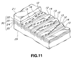
- Fig. 10 is a perspective view partially broken of an optical disk in which grooves are formed in wobbling shape.
- Fig. 11 is a perspective view partially broken of an optical disk in which pits are formed in wobbling shape.
- Fig. 12 is an optical disk apparatus for reproducing an optical disk according to the present invention.
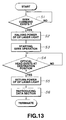
- Fig. 13 is a flow chart for explaining a seek operation in the optical disk apparatus according to the present invention.
- Fig. 1 shows an optical disk which is an example of a recording medium according to the present invention.
- reference numeral 1 designates an optical disk belonging to compact disk (CD) such as CD-ROM and the like, which includes a central hole 2a made to open to both sides of the disk, a recording area a in which for example code information is recorded and a non-recording area (clamping area) extending around the opening portion of the central area 2a.
- CD compact disk
- CD-ROM compact disk
- FIG. 1 designates an optical disk belonging to compact disk (CD) such as CD-ROM and the like, which includes a central hole 2a made to open to both sides of the disk, a recording area a in which for example code information is recorded and a non-recording area (clamping area) extending around the opening portion of the central area 2a.
- Fig. 2 is an enlarged perspective view partially broken of the optical disk 1 shown in Fig. 1.
- the optical disk 1 according to the present invention includes a substrate 29 made of transparent material such as for example polycarbonate or the like, reproducing film 30 in which signals are recorded by means of pre-pit and the recorded signals are reproduced by irradiating laser beam thereon, and protective film 21 for protecting the reproducing film 30, as its prominent factors, and these elements are stacked in shape of layers.
- the optical disk according to the present invention has tracks 12 and grooves (guiding groove) 13 on the reproducing film 30, and further the tracks 12 have pits 14 formed as the pre-pit. That is, this pit 14 is formed by stamping according to a master disk in which signals are preliminarily recorded by means of pits when this optical disk is produced. Thus, by irradiating laser beam on the track 12 in which the pits are formed, its reflected beam is read out so that signals recorded in that optical disk can be reproduced. Meanwhile, this type of signal reproduction method for the optical disks has been already known in optical disk apparatus for CD-ROM.
- Fig. 3 shows a sectional view of the optical disk shown in Fig. 1 in a direction of the radius.
- a depth D G of the aforementioned groove 13 is set to ⁇ /8.
- a depth of a pit for recording data is ⁇ /8 - ⁇ /6 and a depth of a pit for address (e.g., track address, etc.) is set to ⁇ /4.
- the depth D G of the above groove 13 may be of any depth if the condition of ⁇ n/2 + ⁇ /8 (n is an integer except 0) is satisfied.
- the depth D P of the above pit 14 may be of any depth if the depth of the pit for recording data satisfies ⁇ n/2 + ⁇ /8 - ⁇ n/2 + ⁇ /6 (n is an integer except 0) and the depth of the pit for address satisfies ⁇ n/2 + ⁇ /4 (n is an integer except 0).
- the reproducing film 30 of the optical disk 1 according to the present invention has four layers comprising a reflecting film 22 made of Al for reflecting irradiated laser beam, a first reproducing film 23 made of Sb 2 Se 3 , a second reproducing layer 24 made of Bi 2 Te 3 and a third reproducing layer Sb 2 Se 3 , these layers being formed on the substrate 29.
- first - third reproducing layers 23-25 form separate layers of amorphous condition (non-crystal) prior to irradiation of the above laser beam, if laser beam having a power stronger than a predetermined power is irradiated, these first - third reproducing layers 23-25 are melted and mixed so that they are alloyed if the laser beam is stopped and they are left as they are naturally cooled. That is, as shown in Fig.
- an area 26 which is naturally cooled after the above laser beam spot is irradiated is not in such a condition in which different layers of the first - third reproducing layers 23-25 are separately formed in amorphous condition, but in such a condition in which materials composing the first-third reproducing layers 23-25 are mixed and alloyed.
- the power of irradiated laser beam is less than the above predetermined value, melting and mixing of the first-third reproducing layers 23-25 never occurs or occurs a little.
- the above reproducing film 30 produces a different reflectance between then the above first-third reproducing layers 23-25 are in amorphous condition and when they are alloyed.
- the reflectance of the reproducing film 30 prior to irradiation of the laser beam having a stronger power than the above predetermined value is assumed to be Rb and the reflectance of the reproducing film alloyed by irradiating the laser beam having a stronger power than the above predetermined value is assumed to be Ra, a relationship of Rb>Ra can be established.
- the power of the irradiated laser beam is less than the above predetermined value, melting and mixing of the first - third reproducing layers 23-25 never occurs or occurs a little.
- the reflectance Rb and Ra are the same or slightly different from each other. Meanwhile, the above reflectance Rb and Ra can be changed arbitrarily by changing a ratio in film thickness among the first - third reproducing layers 23-25. For example, such a relationship can be changed to Rb ⁇ Ra.
- the above degree of modulation L Ab corresponds to a level of a reproduced signal waveform which is obtained at the address section when initially laser beam is irradiated upon the address section.
- the above degree of modulation LAa corresponds to a level of a reproduced signal waveform which is obtained just when the laser beam is irradiated on the address section and then the laser beam is irradiated on that address section again.
- Fig. 5 shows a relationship between the depth of the pit or groove and the degree of modulation (level of reproduced signal waveform) before (before exposure) and after (after exposure) the irradiation of the laser beam.
- a solid line in the same Figure indicates a relationship between the depth of the pit or groove and the degree of modulation before exposure.
- the dotted line in the same Figure indicates a relationship between the depth of the pit or groove and the degree of modulation after exposure.
- the degree of modulation is the largest when the depth of the pit or groove is ⁇ /4 (the level of reproduced signal waveform becomes the largest). As the depth of the pit or groove comes near 0 or ⁇ /2, the degree of modulation decreases (the level of reproduced signal waveform decreases).
- the pit 14 in the address section is ⁇ /4 in depth and the pit 14 in the data section is ⁇ /8 - ⁇ /6 in depth.
- the degrees of modulation (level of reproduced signal waveform) before and after the irradiation of laser beam are L Ab and L Aa as shown in the same Figure and the degree L Aa of modulation after exposure is a quite large.
- the depth of the pit is ⁇ /8 - ⁇ /6 (only ⁇ /8 is indicated in Fig.
- the degrees of modulation (level of reproduced signal waveform) before and after irradiation of laser (before and after exposure) are L Db and L Da and the degree L Db of modulation before exposure is a quite large.
- the degree L Da of modulation after exposure is very low.
- the above ordinary optical disk reproducing apparatus can correct errors in signals reproduced from a pit in the address section at any time before and after the irradiation of laser beam.
- the optical disk according to the present invention is reproduced with an ordinary optical disk reproducing apparatus, its data section can be reproduced only once but it cannot be reproduced second times and after because error correction is disabled.
- the address section can be reproduced second times and after.
- the depth D P of the pit in the data section is set so as to obtain such a degree of modulation in which the error rate of a reproduction signal after the irradiation of laser beam exceeds the error correction capacity of the above optical disk reproducing apparatus and further the reflectance Rb and Ra of the reproducing film 30 are set in such a manner, that data section can be designed so as to be reproducible only once but not to be reproducible second times and after.
- optical disk is relating to a particular copy right, a possibility of picking out data stored in that optical disk unlimited times is eliminated. If that optical disk is designed for distribution to unlimited destinations, a necessity of collecting those optical disks is eliminated. Further, because the optical disk according to the present invention can allow to reproduce its data only once as described above, it is not suitable for rental use presuming plural uses. Thus, this optical disk is effective in such a case in which that disk is not desired to be used for rental for the reason of copy right.
- the optical disk according to the present invention has the aforementioned reproducing film 30 and as shown in Figs. 6 and 7, respective pits 14 D for recording data are allocated on the track 12 such that their spatial frequency (MTF) is high.
- respective pits 14 A for the address are allocated such that their spatial frequency is low. That is, in the optical disk according to the present invention, signal components of the recording data are concentrated on high frequency band side so as to increase recording density of the data section on the track 12.
- the signal components of the address are concentrated to low frequency band side so as to decrease the recording density of the address section.
- Fig. 6 shows the allocation of pits on a boundary between the data section and the address section and further indicates laser spot 15. Further Fig.
- the amplitude of reproduced signal waveform is large in the address section and small in the data section as shown in Fig. 7.
- Figs. 8A and 8B show a reproduced signal waveform and level before the irradiation of laser beam (that is, reproduced signal waveform and level obtained from the irradiation of laser beam for the first time) and Fig. 8B shows reproduced signal waveform and level after the irradiation of laser beam (that is, reproduced signal waveform and level obtained by the irradiation of laser beam for the second time and after).
- the optical disk 1 according to the present invention can be modified to be an optical disk 50 which allows reproduction on both sides.
- two pieces of the same optical disk having the structure shown in Fig. 1 are prepared and bonded together with the protective films 21 facing each other. That is, two layers indicated by reference numeral 40 in Fig. 9 include the protective film 21 and the reproducing film 30 as shown in Fig. 2.
- the respective reproducing films 30 are structured to be irradiated by laser beam from both side of the optical disk 50 through substrates 29. Further, by bonding the protective films 21 of the two layers 40 through an adhesive layer 20, the optical disk allowing reproduction on both sides can be realized.
- optical disk of the present invention software which can be reproduced only once for example (audio, picture, game software, etc. ) can be supplied in a form of an optical disk designed for read only which can be produced by stamping from a master disk. Thus, it is possible to achieve protection of copy right further effectively.
- address information is recorded on the track 12 by means of pre-pit.
- the address information is recorded on the track 12 by means of the pre-pit, as shown in Fig. 10 for example, it is possible to achieve recording of the address information by forming the grooves 13 by wobbling and modulating the frequency of that wobbling corresponding to the address information.
- Fig. 12 shows a schematic construction of a disk reproducing apparatus 100 for reproducing signals from an optical disk 1 being rotated.
- an optical disk 1 which is a disk shaped recording medium is driven to rotate by a spindle motor 103 through a shaft 102.
- This spindle motor 103 contains a FG signal generator for outputting FG signals accompanied by a rotation of the spindle motor 103 by detecting magnetic flux in a magnet.
- the spindle motor 103 is driven to rotate by spindle drive signals generated by a spindle control system 111 based on the FG signal from the above FG signal generator 104 and subjected to spindle servo.
- the spindle control system 111 enables change of rotation speed of the spindle motor 103 by control from a system controller 107. If the optical disk 101 is driven to rotate according to for example zone CAV (angular velocity constant) or zone CLV (linear velocity constant), the rotation speed of the optical disk 101 must be changed for each zone. Thus, the above system controller 107 controls the spindle control system 111 to change the rotation speed of the optical disk 101. At this time, the system controller 107 determines whether the rotation speed of the optical disk 101 reaches a predetermined speed based on FG lock/unlock signals from the FG lock detector 112.
- zone CAV angular velocity constant
- zone CLV linear velocity constant
- the above FG lock detector 112 determines whether the rotation of the spindle motor 103 is locked by detecting jitters in the FG signal from the FG signal generator 104 and according to a result of this detection, outputs the above FG lock/unlock signals.
- the above FG lock detector 112 contains PLL (phase-locked loop) circuit for phase-locking the above FG signal by means of the PLL circuit.
- An optical head 105 includes an optical part including a laser beam source such as a laser diode and an objective lens, an optical system composed of a photo detector having a beam receiving portion for predetermined pattern and the like, and a biaxial actuator for driving the objective lens vertically or in focusing direction and horizontally or in tracking direction. Further, the optical head 105 is structured so as to be movable in disk diameter direction by means of sledding mechanism comprising a sledding motor and a sledding rail. sledding rail.
- the optical head 105 laser beam projected from the laser diode of the above optical system is concentratedly irradiated on the disk 101 through the objective lens.
- the optical head 105 moves the objective lens in the focusing direction by means of the biaxial actuator to focus on a recording surface of the above disk and further moves the objective lens in the tracking direction to apply the focusing point to a track on the recording surface of the above disk.
- reflected beam from the optical disk 101 is introduced to the above photo detector through the objective lens of the optical system. In this photo detector, the introduced beam is converted to electric signals by photo-electric conversion process.
- Output signals from the optical head 105 are transmitted to a servo signal generating circuit 109.
- This servo signal generating circuit 109 detects for example focus error signals based on so-called astigmatism method or tracking error signals based on push-pull method from the output signals of the optical head 105.
- the above focus error signals and the tracking error signals from the servo signal generating circuit 109 are transmitted to the servo control system 110.
- the servo control system 110 drives the biaxial actuator of the optical head 105 based on the above focus error signal and the tracking error signal to perform focus servo and tracking servo.
- the servo control system 110 generates sled drive signals for moving the optical head 105 to a destination position in disk diameter direction based on control from the system controller 109 and transmits this sled drive signal to a sled driver provided on the optical head 105.
- the sled driver drives the sledding motor of the above sledding mechanism. As a result, the optical head 105 is moved to radius direction of the optical disk 1.
- the disk reproducing apparatus 100 shown in Fig. 12 operates as follows.
- Signals read by the optical head 105 from the optical disk 1 are transmitted to a reproduction system 108.
- This reproduction system 108 demodulates reproduced signals form the optical disk 101 and carries out detection of errors and correction thereof.
- Signals reproduced by this reproduction system 108 are transmitted to for example host computer which is an external component through a system controller 9 and further a terminal 113.
- the system controller 109 determines whether an address for seek destination position and a seek command have been received from the host computer (S1). If the seek command is not received, the processing returns to S1 so that it waits for seek command.
- the system controller 109 If the seek command is received, the system controller 109 outputs laser power halving signal for halving laser power to a laser power control circuit 106.
- the laser power halving circuit 106 controls the laser beam source to halve the laser power to half at the time of reproduction (S2).
- the sledding motor is driven to move the optical head toward a destination position on the optical disk to start the seek operation (S3).
- the laser power is adjusted to half at the time of reproduction so that even if the data section is irradiated by laser beam during the seek operation, the reproducing layer 30 of the data section is not melted, mixed or alloyed.
- the reflectance may be changed. Namely, data in the data section is not deleted so that it can be read at ordinary reproduction.
- the current position address of the optical head can be read through the reproduction system 108.
- the system controller 109 If it is determined that the position address coincides with the destination address, the system controller 109 outputs a laser power restoration signal to the laser power control circuit 106.
- the laser power control circuit 106 controls laser beam source to return the laser power to a laser power at the time of reproduction (S5).
- the laser beam power should be returned to its ordinary power level after the seek operation is completed as stated in the present invention, if there is no opportunity that the laser beam spot settles over the data section for more than a time in which it melts the first-third reproducing layers 23-25, the above described operation of the laser power is not necessary.
- a reproducing film whose reflectance is changed by irradiating laser beam having a higher strength than a predetermined one is formed, the depth of a pre-pit in the data section in which data is recorded by means of the pre-pits is set to less than a quarter of the wavelength of a laser beam and the reproducing film is composed such that its reflectance drops if it is irradiated by a laser beam having a higher strength than a predetermined level.
- the problem relating to copy right can be reduced. For example, for even optical disks permitted to be rented, a necessity of collecting that optical disk can be eliminated and at the same time, it is possible to make that optical disk inhibited from being used for rental.
- the laser power of reproducing optical beam is reduced during seek operation in the recording medium reproducing apparatus according to the present invention, data on the recording medium is never deleted during the seek operation. Further, because the address section can be read by even a week laser power, a destination position can be sought securely.
Landscapes
- Engineering & Computer Science (AREA)
- Computer Security & Cryptography (AREA)
- Physics & Mathematics (AREA)
- Optics & Photonics (AREA)
- Chemical & Material Sciences (AREA)
- Inorganic Chemistry (AREA)
- Optical Recording Or Reproduction (AREA)
- Optical Record Carriers And Manufacture Thereof (AREA)
Applications Claiming Priority (3)
| Application Number | Priority Date | Filing Date | Title |
|---|---|---|---|
| JP116315/96 | 1996-05-10 | ||
| JP11631596 | 1996-05-10 | ||
| JP8116315A JPH09306030A (ja) | 1996-05-10 | 1996-05-10 | 記録媒体 |
Publications (3)
| Publication Number | Publication Date |
|---|---|
| EP0806768A2 true EP0806768A2 (de) | 1997-11-12 |
| EP0806768A3 EP0806768A3 (de) | 1998-07-08 |
| EP0806768B1 EP0806768B1 (de) | 2003-03-19 |
Family
ID=14683958
Family Applications (1)
| Application Number | Title | Priority Date | Filing Date |
|---|---|---|---|
| EP97107472A Expired - Lifetime EP0806768B1 (de) | 1996-05-10 | 1997-05-06 | Aufzeichnungsträger, Vorrichtung zur optischen Wiedergabe von Information sowie Suchmethode |
Country Status (9)
| Country | Link |
|---|---|
| US (1) | US6038207A (de) |
| EP (1) | EP0806768B1 (de) |
| JP (1) | JPH09306030A (de) |
| KR (1) | KR970076726A (de) |
| CN (1) | CN1167312A (de) |
| BR (1) | BR9703115A (de) |
| DE (1) | DE69719846T2 (de) |
| SG (1) | SG48527A1 (de) |
| TW (1) | TW343332B (de) |
Cited By (5)
| Publication number | Priority date | Publication date | Assignee | Title |
|---|---|---|---|---|
| EP0932147A3 (de) * | 1998-01-26 | 2001-01-31 | Eastman Kodak Company | Anzeigemarken auf einer optischen Platte zur Anzeige eines früheren Zugriffs |
| EP0925581A4 (de) * | 1996-09-16 | 2001-04-11 | Spectradisc Corp | Maschinenlesbare optische scheibe mit mittel zur leschinderung |
| US6747930B1 (en) | 1996-12-24 | 2004-06-08 | Hide & Seek Technologies, Inc. | Data protection on an optical disk |
| EP1102248A4 (de) * | 1998-07-28 | 2004-10-20 | Matsushita Electric Industrial Co Ltd | Optische platte und optisches plattenlaufwerk |
| EP1326243A4 (de) * | 2000-09-12 | 2008-04-23 | Tdk Corp | Optisches aufzeichnungsmedium |
Families Citing this family (18)
| Publication number | Priority date | Publication date | Assignee | Title |
|---|---|---|---|---|
| JP3890737B2 (ja) | 1998-04-14 | 2007-03-07 | 株式会社日立製作所 | ディジタル映像信号または音声信号の再生装置及び再生方法 |
| US6338933B1 (en) * | 1998-06-25 | 2002-01-15 | Spectradisc Corporation | Methods and apparatus for rendering an optically encoded medium unreadable |
| US6531262B1 (en) | 1998-06-25 | 2003-03-11 | Spectradisc Corporation | Methods and apparatus for rendering an optically encoded medium unreadable and tamper-resistant |
| KR100656687B1 (ko) * | 1999-05-19 | 2006-12-18 | 소니 가부시끼 가이샤 | 광 디스크 기록 장치, 광 디스크 기록 방법, 광 디스크 및 광디스크 재생장치 |
| US7055739B1 (en) * | 1999-05-25 | 2006-06-06 | Silverbrook Research Pty Ltd | Identity-coded surface with reference points |
| JP2000348388A (ja) * | 1999-06-04 | 2000-12-15 | Sharp Corp | 光記録媒体 |
| DE60042766D1 (de) * | 1999-06-30 | 2009-09-24 | Sharp Kk | Optische Plattenvorrichtung zur Wiedergabe einer optischen Platte mit darin geformten Pits verschiedener Tiefe |
| AU777945B2 (en) * | 1999-07-12 | 2004-11-04 | Flexplay Technologies, Inc. | Disposable optical storage media and manufacturing method |
| JP3962522B2 (ja) * | 2000-02-14 | 2007-08-22 | パイオニア株式会社 | 情報記録媒体 |
| JP3922424B2 (ja) * | 2000-07-25 | 2007-05-30 | パイオニア株式会社 | 光学式記録媒体、光学式記録媒体製造装置及び光学式記録媒体製造方法 |
| US6982109B2 (en) * | 2000-12-11 | 2006-01-03 | Flexplay Technologies, Inc. | Method for rendering surface layer of limited play disk lightfast |
| JPWO2002080172A1 (ja) * | 2001-03-30 | 2004-07-22 | ソニー株式会社 | 記録媒体の記録又は再生装置並びにデータの出力制御方法 |
| WO2002099470A2 (en) * | 2001-06-05 | 2002-12-12 | Flexplay Technologies, Inc. | Limited play optical devices with interstitial reactive layer and methods of making same |
| US20040158871A1 (en) * | 2003-02-04 | 2004-08-12 | Bulldog Investments, Lp | Automated digital media vending apparatus |
| WO2006130496A1 (en) * | 2005-05-27 | 2006-12-07 | Consumable Media Llc | Limited play optical discs |
| WO2007139077A1 (ja) | 2006-05-30 | 2007-12-06 | Panasonic Corporation | 光ディスク、光ディスク製造方法、光ディスク記録装置及び光ディスク再生装置 |
| US20090075015A1 (en) * | 2007-07-24 | 2009-03-19 | Detty Michael R | Limited Play Optical Discs |
| CN109059795B (zh) * | 2018-06-29 | 2020-11-03 | 歌尔光学科技有限公司 | 深度测量方法、深度测量装置及拍摄设备 |
Family Cites Families (13)
| Publication number | Priority date | Publication date | Assignee | Title |
|---|---|---|---|---|
| US4577306A (en) * | 1980-02-25 | 1986-03-18 | Eastman Kodak Company | Method for optically writing and/or reading information on optical recording elements |
| US4360908A (en) * | 1980-02-25 | 1982-11-23 | Eastman Kodak Company | Physically optimized optical disc structure, method and apparatus |
| US4538159A (en) * | 1984-04-16 | 1985-08-27 | Eastman Kodak Company | Ceramic overcoated optical recording element |
| US4527173A (en) * | 1984-04-16 | 1985-07-02 | Eastman Kodak Company | Erasable, reusable optical recording element and method |
| US4924436A (en) * | 1987-06-22 | 1990-05-08 | Energy Conversion Devices, Inc. | Data storage device having a phase change memory medium reversible by direct overwrite and method of direct overwrite |
| DE4019301A1 (de) * | 1990-06-16 | 1991-12-19 | Basf Ag | Reversibler optischer aufzeichnungstraeger vom phasenwechsel-typ |
| JPH04167237A (ja) * | 1990-10-31 | 1992-06-15 | Sony Corp | 光ディスク |
| JP3412163B2 (ja) * | 1991-05-24 | 2003-06-03 | 松下電器産業株式会社 | 光磁気ディスク装置 |
| JP3160632B2 (ja) * | 1991-09-27 | 2001-04-25 | ソニー株式会社 | 光ディスクとその再生方法 |
| JPH05101471A (ja) * | 1991-10-08 | 1993-04-23 | Sony Corp | 光磁気記録再生方法 |
| JP3084969B2 (ja) * | 1992-10-16 | 2000-09-04 | 松下電器産業株式会社 | 再生装置と記録装置とケース入り記録媒体と記録媒体の初期化装置 |
| JPH076368A (ja) * | 1993-02-03 | 1995-01-10 | Matsushita Electric Ind Co Ltd | 光ディスク装置および記録再生方法 |
| EP0643391B1 (de) * | 1993-09-07 | 2000-02-02 | Hitachi, Ltd. | Informationsaufzeichnungsträger, optische Platten und Wiedergabesystem |
-
1996
- 1996-05-10 JP JP8116315A patent/JPH09306030A/ja not_active Withdrawn
-
1997
- 1997-04-15 TW TW086104858A patent/TW343332B/zh active
- 1997-04-29 SG SG1997001346A patent/SG48527A1/en unknown
- 1997-04-30 US US08/846,777 patent/US6038207A/en not_active Expired - Fee Related
- 1997-05-06 EP EP97107472A patent/EP0806768B1/de not_active Expired - Lifetime
- 1997-05-06 DE DE69719846T patent/DE69719846T2/de not_active Expired - Fee Related
- 1997-05-09 KR KR1019970017892A patent/KR970076726A/ko not_active Withdrawn
- 1997-05-09 BR BR9703115A patent/BR9703115A/pt not_active IP Right Cessation
- 1997-05-09 CN CN97111144A patent/CN1167312A/zh active Pending
Cited By (8)
| Publication number | Priority date | Publication date | Assignee | Title |
|---|---|---|---|---|
| EP0925581A4 (de) * | 1996-09-16 | 2001-04-11 | Spectradisc Corp | Maschinenlesbare optische scheibe mit mittel zur leschinderung |
| US6343063B1 (en) | 1996-09-16 | 2002-01-29 | Spectradisc Corp. | Machine-readable optical disc with reading-inhibit agent |
| US6434109B2 (en) | 1996-09-16 | 2002-08-13 | Spectradisc Corporation | Machine-readable optical disc with reading-inhibit agent |
| USRE42011E1 (en) | 1996-09-16 | 2010-12-28 | Flexplay Technologies, Inc. | Machine-readable optical disc with reading-inhibit agent |
| US6747930B1 (en) | 1996-12-24 | 2004-06-08 | Hide & Seek Technologies, Inc. | Data protection on an optical disk |
| EP0932147A3 (de) * | 1998-01-26 | 2001-01-31 | Eastman Kodak Company | Anzeigemarken auf einer optischen Platte zur Anzeige eines früheren Zugriffs |
| EP1102248A4 (de) * | 1998-07-28 | 2004-10-20 | Matsushita Electric Industrial Co Ltd | Optische platte und optisches plattenlaufwerk |
| EP1326243A4 (de) * | 2000-09-12 | 2008-04-23 | Tdk Corp | Optisches aufzeichnungsmedium |
Also Published As
| Publication number | Publication date |
|---|---|
| US6038207A (en) | 2000-03-14 |
| KR970076726A (ko) | 1997-12-12 |
| TW343332B (en) | 1998-10-21 |
| DE69719846D1 (de) | 2003-04-24 |
| SG48527A1 (en) | 1998-04-17 |
| EP0806768A3 (de) | 1998-07-08 |
| BR9703115A (pt) | 1998-10-27 |
| CN1167312A (zh) | 1997-12-10 |
| EP0806768B1 (de) | 2003-03-19 |
| JPH09306030A (ja) | 1997-11-28 |
| DE69719846T2 (de) | 2004-01-22 |
| MX9703324A (es) | 1997-11-29 |
Similar Documents
| Publication | Publication Date | Title |
|---|---|---|
| EP0806768B1 (de) | Aufzeichnungsträger, Vorrichtung zur optischen Wiedergabe von Information sowie Suchmethode | |
| KR940002000B1 (ko) | 광디스크기록/재생장치 및 그 제어방법 | |
| US4942565A (en) | Apparatus for recording a wobbling, spiral guide groove on an optical disc | |
| EP0595349B1 (de) | Optische Platte | |
| JPH03219434A (ja) | 光学的情報記録媒体 | |
| JP2983920B2 (ja) | 互換再生可能なピックアップ調整用光記録媒体およびその調整方法 | |
| JP3059026B2 (ja) | 光記録媒体、記録装置および記録方法 | |
| JPH0427610B2 (de) | ||
| JP4508297B2 (ja) | 光ディスク及び光ディスク装置 | |
| JPH0750014A (ja) | 光記録媒体 | |
| JP2798245B2 (ja) | 光ディスク装置 | |
| US7701813B2 (en) | Method for recording to and reproducing from an optical recording medium, optical recording medium, and recording and reproduction apparatus for the same | |
| JPH01307020A (ja) | 光ディスク装置 | |
| MXPA97003324A (en) | Registration media, optic information reproduction apparatus and localization method | |
| JP2954037B2 (ja) | 円盤状記録媒体 | |
| JP2892325B2 (ja) | 光ディスク装置 | |
| JP2915855B2 (ja) | 光ディスク装置 | |
| JP3985767B2 (ja) | 光ディスク装置及び光ディスク再生方法 | |
| JP2892326B2 (ja) | 光ディスク装置 | |
| JP3059172B2 (ja) | 光記録媒体、記録装置および記録方法 | |
| JP3573593B2 (ja) | 相変化光ディスク | |
| JP2881041B2 (ja) | 光ディスク再生装置 | |
| JPH10302404A (ja) | コピー防止用記録媒体 | |
| JP2672617B2 (ja) | 情報記録装置 | |
| JPH03122821A (ja) | 光ディスク再生装置 |
Legal Events
| Date | Code | Title | Description |
|---|---|---|---|
| PUAI | Public reference made under article 153(3) epc to a published international application that has entered the european phase |
Free format text: ORIGINAL CODE: 0009012 |
|
| AK | Designated contracting states |
Kind code of ref document: A2 Designated state(s): DE FR GB |
|
| PUAL | Search report despatched |
Free format text: ORIGINAL CODE: 0009013 |
|
| AK | Designated contracting states |
Kind code of ref document: A3 Designated state(s): DE FR GB |
|
| 17P | Request for examination filed |
Effective date: 19981110 |
|
| GRAG | Despatch of communication of intention to grant |
Free format text: ORIGINAL CODE: EPIDOS AGRA |
|
| 17Q | First examination report despatched |
Effective date: 20020502 |
|
| GRAG | Despatch of communication of intention to grant |
Free format text: ORIGINAL CODE: EPIDOS AGRA |
|
| GRAH | Despatch of communication of intention to grant a patent |
Free format text: ORIGINAL CODE: EPIDOS IGRA |
|
| GRAH | Despatch of communication of intention to grant a patent |
Free format text: ORIGINAL CODE: EPIDOS IGRA |
|
| GRAA | (expected) grant |
Free format text: ORIGINAL CODE: 0009210 |
|
| AK | Designated contracting states |
Designated state(s): DE FR GB |
|
| REG | Reference to a national code |
Ref country code: GB Ref legal event code: FG4D |
|
| REF | Corresponds to: |
Ref document number: 69719846 Country of ref document: DE Date of ref document: 20030424 Kind code of ref document: P |
|
| PGFP | Annual fee paid to national office [announced via postgrant information from national office to epo] |
Ref country code: GB Payment date: 20030430 Year of fee payment: 7 |
|
| PGFP | Annual fee paid to national office [announced via postgrant information from national office to epo] |
Ref country code: FR Payment date: 20030508 Year of fee payment: 7 |
|
| PGFP | Annual fee paid to national office [announced via postgrant information from national office to epo] |
Ref country code: DE Payment date: 20030515 Year of fee payment: 7 |
|
| ET | Fr: translation filed | ||
| PLBE | No opposition filed within time limit |
Free format text: ORIGINAL CODE: 0009261 |
|
| STAA | Information on the status of an ep patent application or granted ep patent |
Free format text: STATUS: NO OPPOSITION FILED WITHIN TIME LIMIT |
|
| 26N | No opposition filed |
Effective date: 20031222 |
|
| PG25 | Lapsed in a contracting state [announced via postgrant information from national office to epo] |
Ref country code: GB Free format text: LAPSE BECAUSE OF NON-PAYMENT OF DUE FEES Effective date: 20040506 |
|
| PG25 | Lapsed in a contracting state [announced via postgrant information from national office to epo] |
Ref country code: DE Free format text: LAPSE BECAUSE OF NON-PAYMENT OF DUE FEES Effective date: 20041201 |
|
| GBPC | Gb: european patent ceased through non-payment of renewal fee |
Effective date: 20040506 |
|
| PG25 | Lapsed in a contracting state [announced via postgrant information from national office to epo] |
Ref country code: FR Free format text: LAPSE BECAUSE OF NON-PAYMENT OF DUE FEES Effective date: 20050131 |
|
| REG | Reference to a national code |
Ref country code: FR Ref legal event code: ST |