EP0806607B1 - Connecting element - Google Patents
Connecting element Download PDFInfo
- Publication number
- EP0806607B1 EP0806607B1 EP97201275A EP97201275A EP0806607B1 EP 0806607 B1 EP0806607 B1 EP 0806607B1 EP 97201275 A EP97201275 A EP 97201275A EP 97201275 A EP97201275 A EP 97201275A EP 0806607 B1 EP0806607 B1 EP 0806607B1
- Authority
- EP
- European Patent Office
- Prior art keywords
- strip
- tag
- luminaire
- blade
- tab
- Prior art date
- Legal status (The legal status is an assumption and is not a legal conclusion. Google has not performed a legal analysis and makes no representation as to the accuracy of the status listed.)
- Expired - Lifetime
Links
Images
Classifications
-
- F—MECHANICAL ENGINEERING; LIGHTING; HEATING; WEAPONS; BLASTING
- F21—LIGHTING
- F21V—FUNCTIONAL FEATURES OR DETAILS OF LIGHTING DEVICES OR SYSTEMS THEREOF; STRUCTURAL COMBINATIONS OF LIGHTING DEVICES WITH OTHER ARTICLES, NOT OTHERWISE PROVIDED FOR
- F21V21/00—Supporting, suspending, or attaching arrangements for lighting devices; Hand grips
- F21V21/02—Wall, ceiling, or floor bases; Fixing pendants or arms to the bases
- F21V21/04—Recessed bases
Definitions
- the present invention relates to a recessed luminaire in a false ceiling, provided with a band comprising an axial cut, and its fixing member comprising a blade of elastic material provided with a means of attachment to the strip, allowing the sliding the along the band, means which has a hooking tab wider than the width of the notch, which tab is attached to the blade by a bridge narrower than the width of the notch, so that when use, the bridge passes through the notch and the lug rests on the back of the strip, while, when fixing the device, the end of the blade rests on the top of the scythe ceiling, the blade then forming an acute angle with the band.
- a fixing member for a recessed, provided with a band with an axial notch is known from FR-A-2723988.
- the blade can be slidably locked relative to the strip because it carries at its end a trapezoidal part which engages and gets stuck in the notch.
- An object of the invention is, inter alia, to improve the locking safety of the fastener relative to the strip, and to facilitate the unlocking, if necessary.
- the attachment means is disposed at the end of the blade, on the side opposite to that which rests on the false ceiling, and the member further comprises a sliding strap which, in use , surround both the band and the blade.
- This arrangement makes it possible, in a simple manner, to block the blade sliding vis-à-vis the band, while pressing against the ceiling.
- the blade advantageously forms an angle whose vertex is turned towards the band, so that the blade rests on the band by the top of the angle, in the fixing position.
- the blade has a plurality of slots or transverse projections, and the bracelet a hooking means likely to hang.
- the bracelet preferably comprises a raised piece for handling it.
- a recessed luminaire is advantageously equipped with at least one fastener according to the invention.
- a luminaire to be embedded in a circular opening of a false ceiling is shown by way of example, in perspective, on a reduced scale, under the reference 10.
- This luminaire is provided with a strip 11 having a notch or axial slot, an arrangement 12 for fixing a lamp, for example an incorporated reflector lamp, and a flange 13.
- a lamp for example an incorporated reflector lamp
- a flange 13 In use, all the parts 11 and 12 is inside the false ceiling, and the horizontal element of the flange 13 is supported under the ceiling. It is clear, however, that object fixed in a ceiling, other than a luminaire of this kind, can make use of the fixing member according to the invention.
- a part of the band 11 is also represented, on a larger scale, in the position of use, that is to say with the fastener in place.
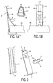
- the band 11 is seen by its edge in Figure 1A, and front view, with its notch or slot 17, in Figure 1B.
- the fixing member comprises a blade 1 of elastic material, which can slide along the aforesaid strip 11 (to the right of the strip at A, or in front of the strip at B). The lower end of the blade rests on the top of the false ceiling 16, and the blade 1 forms an acute angle with the band 11.
- the upper end of the blade is engaged in the notch 17 of the band by means of a fastening means 2 which will be described with reference to Figure 2.
- a sliding strap 3 surrounds both the strip and the blade.
- the bracelet comprises a piece 4 in relief for handling it.
- the bracelet could also be mounted in the other direction, with the piece 4 on the left in Figure 1A.
- the section 13 of the flange of the luminaire is supported under the ceiling 16.
- the blade forms an angle 18 whose apex is turned towards the strip.
- the blade is supported on the band by the top of the angle.
- FIG. 2 represents a part of the strip 11 with the notch 17, a blade 1, and a bracelet 3.
- the blade 1 comprises, at its upper end, a hooking tab 2 wider than the width of the notch 17, tab which is attached to the blade by a bridge 9 less wide than the width of the notch 17, so that the bridge passes through the notch and the hooking tab clings behind the band.
- the blade 1 has a plurality of slots or transverse projections 8, and the bracelet 3 carries a tab 14, visible by transparency, capable of engaging in one of the slots 8, or to hook to one of the projections 8, in the case where it concerns projections.
- tab 14 is in the extension of the piece 4 embossed to manipulate the bracelet, but the skilled person can easily imagine different other forms for this bracelet, including the material used, and its mode of work.
- the blade further has at its lower end spikes 5, 6 which prevent it from sliding on the false ceiling, and a tab 7 to handle it more easily. Near the end which carries the attachment means 2, it forms an angle 18 whose apex is turned towards the band.
- the bracelet 3 is open at 15, to allow threading around the blade 1, despite the presence of the parts 9 or 7.
Abstract
Description
La présente invention concerne un luminaire à encastrer dans un faux plafond, muni d'une bande comportant une entaille axiale, et son organe de fixation comprenant une lame en matériau élastique munie d'un moyen d'accrochage à la bande, permettant le coulissement le long de la bande, moyen qui comporte une patte d'accrochage plus large que la largeur de l'entaille, patte qui est attachée à la lame par un pont moins large que la largeur de l'entaille, de façon que, lors de l'utilisation, le pont passe au travers de l'entaille et la patte s'appuie sur l'arrière de la bande, cependant que, lors de la fixation du dispositif, l'extrémité de la lame s'appuie sur le dessus du faux plafond, la lame formant alors un angle aigu avec la bande.The present invention relates to a recessed luminaire in a false ceiling, provided with a band comprising an axial cut, and its fixing member comprising a blade of elastic material provided with a means of attachment to the strip, allowing the sliding the along the band, means which has a hooking tab wider than the width of the notch, which tab is attached to the blade by a bridge narrower than the width of the notch, so that when use, the bridge passes through the notch and the lug rests on the back of the strip, while, when fixing the device, the end of the blade rests on the top of the scythe ceiling, the blade then forming an acute angle with the band.
Un organe de fixation pour un encastré, muni d'une bande avec une entaille axiale, est connu du document FR-A-2723988. Selon ce document, la lame peut être bloquée en coulissement par rapport à la bande du fait qu'elle porte à son extrémité une partie trapézoïdale qui s'engage et se coince dans l'entaille.A fixing member for a recessed, provided with a band with an axial notch, is known from FR-A-2723988. According to this document, the blade can be slidably locked relative to the strip because it carries at its end a trapezoidal part which engages and gets stuck in the notch.
L'état de la technique le plus proche, DE 31 09 885, décrit un luminaire selon le préambule de la revendication 1.The closest state of the art, DE 31 09 885, discloses a luminaire according to the preamble of
Un objet de l'invention est, entre autres, d'améliorer la sûreté de blocage de l'organe de fixation par rapport à la bande, et d'en faciliter le déblocage, en cas de besoin.An object of the invention is, inter alia, to improve the locking safety of the fastener relative to the strip, and to facilitate the unlocking, if necessary.
A cet effet, le moyen d'accrochage est disposé à l'extrémité de la lame, du côté opposé à celui qui s'appuie sur le faux plafond, et l'organe comprend en outre un bracelet coulissant qui, lors de l'utilisation, entoure à la fois la bande et la lame.For this purpose, the attachment means is disposed at the end of the blade, on the side opposite to that which rests on the false ceiling, and the member further comprises a sliding strap which, in use , surround both the band and the blade.
Cet agencement permet, de façon simple, de bloquer la lame en coulissement vis-à-vis de la bande, tout en l'appuyant contre le plafond.This arrangement makes it possible, in a simple manner, to block the blade sliding vis-à-vis the band, while pressing against the ceiling.
A proximité de l'extrémité qui porte le moyen d'accrochage, la lame forme avantageusement un angle dont le sommet est tourné vers la bande, de façon que la lame s'appuie sur la bande par le sommet de l'angle, en position de fixation.Near the end which carries the attachment means, the blade advantageously forms an angle whose vertex is turned towards the band, so that the blade rests on the band by the top of the angle, in the fixing position.
Ainsi le blocage de la lame par rapport à la bande est plus efficace.Thus blocking the blade relative to the band is more effective.
Avantageusement, la lame comporte une pluralité de fentes ou de saillies transversales, et le bracelet un moyen d'accrochage susceptible de s'y accrocher.Advantageously, the blade has a plurality of slots or transverse projections, and the bracelet a hooking means likely to hang.
Ainsi un blocage du bracelet est obtenu de façon sûre.Thus a lock of the bracelet is obtained safely.
Le bracelet comporte de préférence une pièce en relief permettant de le manipuler.The bracelet preferably comprises a raised piece for handling it.
Un luminaire encastré est avantageusement équipé d'au moins un organe de fixation selon l'invention.A recessed luminaire is advantageously equipped with at least one fastener according to the invention.
Ces aspects de l'invention ainsi que d'autres aspects plus détaillés apparaîtront plus clairement grâce à la description suivante d'un mode de réalisation constituant un exemple non limitatif.
- La figure 1 représente une partie de la bande comportant une entaille axiale, et l'organe qui s'y accroche, avec en A la bande vue de profil, et en B la bande vue de face.
- La figure 2 représente, en perspective, séparés l'un de l'autre, une partie de la bande comportant une entaille axiale, la lame et le bracelet.
- Figure 1 shows a portion of the strip having an axial cut, and the member which is attached to it, with A band seen in profile, and B the band seen from the front.
- Figure 2 shows, in perspective, separated from one another, a portion of the band having an axial notch, the blade and the bracelet.
Dans la figure 1, un luminaire à encastrer dans une ouverture circulaire d'un faux plafond est représenté à titre d'exemple, en perspective, à échelle réduite, sous la référence 10. Ce luminaire est muni d'une bande 11 comportant une entaille ou fente axiale, d'un arrangement 12 pour fixer une lampe, par exemple une lampe à réflecteur incorporé, et d'une collerette 13. Lors de l'utilisation, l'ensemble des pièces 11 et 12 est à l'intérieur du faux plafond, et l'élément horizontal de la collerette 13 est appuyé sous le plafond. Il est clair toutefois que tout objet fixé dans un plafond, autre qu'un luminaire de cette sorte, peut faire usage de l'organe de fixation selon l'invention.In Figure 1, a luminaire to be embedded in a circular opening of a false ceiling is shown by way of example, in perspective, on a reduced scale, under the
Une partie de la bande 11 est représentée par ailleurs, à plus grande échelle, en position d'utilisation, c'est-à-dire avec l'organe de fixation en place. La bande 11 est vue par sa tranche sur la figure 1A, et vue de face, avec son entaille ou fente 17, sur la figure 1B. L'organe de fixation comprend une lame 1 en matériau élastique, qui peut coulisser le long de la susdite bande 11 (à droite de la bande, en A, ou devant la bande, en B). L'extrémité inférieure de la lame s'appuie sur le dessus du faux plafond 16, et la lame 1 forme un angle aigu avec la bande 11. L'extrémité supérieure de la lame est engagée dans l'entaille 17 de la bande au moyen d'un moyen d'accrochage 2 qui sera décrit en regard de la figure 2. Un bracelet coulissant 3 entoure à la fois la bande et la lame. Il comporte une pièce 4 en relief permettant de le manipuler. Bien entendu, le bracelet pourrait aussi être monté dans l'autre sens, avec la pièce 4 à gauche sur la figure 1A. La section 13 de la collerette du luminaire est appuyée sous le plafond 16. A proximité de l'extrémité qui porte le moyen d'accrochage, la lame forme un angle 18 dont le sommet est tourné vers la bande. Ainsi la lame est appuyée sur la bande par le sommet de l'angle.A part of the
La figure 2 représente une partie de la bande 11 avec l'entaille 17, une lame 1, et un bracelet 3. La lame 1 comporte, à son extrémité supérieure, une patte d'accrochage 2 plus large que la largeur de l'entaille 17, patte qui est attachée à la lame par un pont 9 moins large que la largeur de l'entaille 17, de façon que le pont passe au travers de l'entaille et la patte d'accrochage s'accroche derrière la bande.FIG. 2 represents a part of the
La lame 1 comporte une pluralité de fentes ou de saillies 8 transversales, et le bracelet 3 porte une patte 14, visible par transparence, susceptible de s'engager dans une des fentes 8, ou de s'accrocher à une des saillies 8, dans le cas où il s'agit de saillies. Ici la patte 14 est dans le prolongement de la pièce 4 en relief permettant de manipuler le bracelet, mais l'homme du métier peut imaginer facilement différentes autres formes pour ce bracelet, notamment selon la matière utilisée, et son mode de travail. La lame porte en outre à son extrémité inférieure des pointes 5, 6 qui l'empêchent de glisser sur le faux plafond, et une patte 7 pour la manipuler plus aisément. A proximité de l'extrémité qui porte le moyen d'accrochage 2, elle forme un angle 18 dont le sommet est tourné vers la bande. Le bracelet 3 est ouvert en 15, pour permettre de l'enfiler autour de la lame 1, malgré la présence des pièces 9 ou 7.The
Claims (5)
- A luminaire (10) that is to be incorporated into a false ceiling (16) and that is provided with a strip (11) having an axial incision (17), and with a tag (1) of an elastic material provided with hooking means to be applied to said strip enabling said tag to glide along the strip, which means comprise a hooking tab (2) of greater width than the incision, which hooking tab is attached to the tag via a bridge (9) of smaller width than the incision, such that during use the bridge is passed through the incision and the tab bears on the rear of the strip, while upon a fixation of the luminaire the end (5, 6) of the tag applies itself to the upper side of the false ceiling, the tag thus enclosing an acute angle with the strip, said hooking means being arranged at the end of the tag at the side opposed to that which bears on the false ceiling during use, characterized in that the luminaire in addition comprises a sliding clamp (3) which surrounds both the strip and the tag during use.
- A luminaire as claimed in claim 1, characterized in that in the vicinity of the end that carries the hooking means, the tag encloses an angle (18) whose apex is directed towards the strip, such that the tag bears with the apex of said angle on the strip, in the fixation position.
- A luminaire as claimed in claim 1 or 2, characterized in that the tag comprises a plurality of transverse slots or projections (8), and the clamp comprises a retaining means (14) capable of anchoring itself therein.
- A luminaire as claimed in any one of the claims 1 to 3, characterized in that the clamp comprises a portion in relief (4) such that it can be manipulated.
- A luminaire as claimed in any one of the claims 1 to 4, characterized in that the clamp is open.
Applications Claiming Priority (2)
| Application Number | Priority Date | Filing Date | Title |
|---|---|---|---|
| FR9605637A FR2748301A1 (en) | 1996-05-06 | 1996-05-06 | FASTENER |
| FR9605637 | 1996-05-06 |
Publications (2)
| Publication Number | Publication Date |
|---|---|
| EP0806607A1 EP0806607A1 (en) | 1997-11-12 |
| EP0806607B1 true EP0806607B1 (en) | 2006-10-25 |
Family
ID=9491867
Family Applications (1)
| Application Number | Title | Priority Date | Filing Date |
|---|---|---|---|
| EP97201275A Expired - Lifetime EP0806607B1 (en) | 1996-05-06 | 1997-04-28 | Connecting element |
Country Status (4)
| Country | Link |
|---|---|
| EP (1) | EP0806607B1 (en) |
| AT (1) | ATE343763T1 (en) |
| DE (1) | DE69736851T2 (en) |
| FR (1) | FR2748301A1 (en) |
Families Citing this family (2)
| Publication number | Priority date | Publication date | Assignee | Title |
|---|---|---|---|---|
| TR200100179A2 (en) * | 2001-01-19 | 2002-08-21 | Bayraktarlar Motorlu Vasitalar Ti̇c. Ve San. A.Ş. | A configuration and method for positioning recessed luminaires mounted on the ceiling |
| GB2421069A (en) * | 2004-12-08 | 2006-06-14 | Illuma Lighting Ltd | Adjustable housing for recessed ceiling light |
Family Cites Families (7)
| Publication number | Priority date | Publication date | Assignee | Title |
|---|---|---|---|---|
| FR2434334A1 (en) * | 1978-08-22 | 1980-03-21 | Bonnet Robert | Support for attaching light fitting to false ceiling - has spring loaded tongues which abut against upper surface of ceiling mounted on pair of uprights |
| US4250540A (en) * | 1979-08-23 | 1981-02-10 | Mcgraw-Edison Co. | Mounting arrangement for recessed light fixture housing |
| DE3109885A1 (en) * | 1981-03-14 | 1982-09-23 | Hoffmeister-Leuchten GmbH & Co KG, 5880 Lüdenscheid | Electric light fixture for installation in prefabricated false sealings |
| ATE105623T1 (en) * | 1989-06-27 | 1994-05-15 | Emi Plc Thorn | FIXING DEVICE FOR A LAMP. |
| KR940000840B1 (en) * | 1991-03-21 | 1994-02-02 | 삼성항공산업 주식회사 | Lens |
| IT1251044B (en) * | 1991-08-02 | 1995-05-02 | Reggiani Illuminazione | HOOKING DEVICE FOR A BODY IN A HOLE, IN PARTICULAR FOR FLUSH-MOUNTED EQUIPMENT IN PANELS |
| DE29507478U1 (en) * | 1995-05-05 | 1995-07-06 | Jancik Manfred | Recessed ceiling light |
-
1996
- 1996-05-06 FR FR9605637A patent/FR2748301A1/en not_active Withdrawn
-
1997
- 1997-04-28 EP EP97201275A patent/EP0806607B1/en not_active Expired - Lifetime
- 1997-04-28 DE DE69736851T patent/DE69736851T2/en not_active Expired - Lifetime
- 1997-04-28 AT AT97201275T patent/ATE343763T1/en active
Also Published As
| Publication number | Publication date |
|---|---|
| DE69736851T2 (en) | 2007-06-06 |
| EP0806607A1 (en) | 1997-11-12 |
| ATE343763T1 (en) | 2006-11-15 |
| DE69736851D1 (en) | 2006-12-07 |
| FR2748301A1 (en) | 1997-11-07 |
Similar Documents
| Publication | Publication Date | Title |
|---|---|---|
| CA2026259C (en) | Pencil holder for safety helmet | |
| FR2852157A1 (en) | Fixation device for fixing wire on carrier unit, has wings with end in form of T that has arm adapted to support on face of carrier unit opposed to plain surface at edge of opening | |
| FR2477851A2 (en) | SLIDING CLOSURE CURRENT HAVING A REPORTED BODY | |
| EP0806607B1 (en) | Connecting element | |
| FR2665496A1 (en) | FLOATING CALIPER FOR DISC BRAKE WITH PARTIAL FITTINGS. | |
| FR2872109A1 (en) | Lighting unit fixing device for motor vehicle, has locking housing with wedging clamp unit inserted in opening, in the form of locking hole, of vehicle body and rotated at certain degrees in sliding position to lock housing in body | |
| FR2540198A1 (en) | AXIS PUSH FASTENING CLAMP FOR BOLT THROUGH A STRUCTURAL ELEMENT | |
| FR2654161A1 (en) | LIAISON CLIP, IN PARTICULAR FOR THE ASSEMBLY OF TWO PROFILES. | |
| EP0153542A1 (en) | Clamp and process for producing it | |
| FR2704381A1 (en) | Tracking device for electrical conductor. | |
| EP1282374B1 (en) | Individual anti-theft device for rings or the like | |
| EP0985873A1 (en) | Luminaire having a safety lock, in particular for use in explosive gases | |
| FR2687439A1 (en) | Nut with tapped shank and element such as a panel equipped with this nut | |
| EP0985834B1 (en) | Device in the form of a plate for fastening at least one element on to another one | |
| FR2760050A1 (en) | DEVICE FOR STAPLING A WORKPIECE ON A SUPPORT | |
| FR2579006A1 (en) | Electric bar support | |
| EP1972495A2 (en) | Handle designed for handling a case of a lighting/signalling device for an automobile and method of handling such a case | |
| FR2741121A1 (en) | Security screen mounting for machine tool | |
| FR2649433A1 (en) | Fitting strip for wall covering | |
| FR2741275A1 (en) | SKI FIXING EQUIPPED WITH A DETACHABLE BRAKE | |
| EP0253736B1 (en) | Strip-fastener | |
| FR2741136A1 (en) | BYPASS SUPPORT, IN PARTICULAR FOR WIRE ROPE PATH | |
| FR2765660A1 (en) | Quick release protective cage for emergency lighting | |
| EP0657657B1 (en) | Element for mounting accessories on a perforated wall | |
| GB2370068A (en) | Wire rope grip |
Legal Events
| Date | Code | Title | Description |
|---|---|---|---|
| PUAI | Public reference made under article 153(3) epc to a published international application that has entered the european phase |
Free format text: ORIGINAL CODE: 0009012 |
|
| AK | Designated contracting states |
Kind code of ref document: A1 Designated state(s): AT DE FR GB IT |
|
| 17P | Request for examination filed |
Effective date: 19980512 |
|
| GRAP | Despatch of communication of intention to grant a patent |
Free format text: ORIGINAL CODE: EPIDOSNIGR1 |
|
| GRAS | Grant fee paid |
Free format text: ORIGINAL CODE: EPIDOSNIGR3 |
|
| GRAA | (expected) grant |
Free format text: ORIGINAL CODE: 0009210 |
|
| AK | Designated contracting states |
Kind code of ref document: B1 Designated state(s): AT DE FR GB IT |
|
| PG25 | Lapsed in a contracting state [announced via postgrant information from national office to epo] |
Ref country code: IT Free format text: LAPSE BECAUSE OF FAILURE TO SUBMIT A TRANSLATION OF THE DESCRIPTION OR TO PAY THE FEE WITHIN THE PRESCRIBED TIME-LIMIT;WARNING: LAPSES OF ITALIAN PATENTS WITH EFFECTIVE DATE BEFORE 2007 MAY HAVE OCCURRED AT ANY TIME BEFORE 2007. THE CORRECT EFFECTIVE DATE MAY BE DIFFERENT FROM THE ONE RECORDED. Effective date: 20061025 |
|
| REG | Reference to a national code |
Ref country code: GB Ref legal event code: FG4D Free format text: NOT ENGLISH |
|
| REF | Corresponds to: |
Ref document number: 69736851 Country of ref document: DE Date of ref document: 20061207 Kind code of ref document: P |
|
| GBT | Gb: translation of ep patent filed (gb section 77(6)(a)/1977) |
Effective date: 20070118 |
|
| REG | Reference to a national code |
Ref country code: GB Ref legal event code: 746 Effective date: 20070118 |
|
| PLBE | No opposition filed within time limit |
Free format text: ORIGINAL CODE: 0009261 |
|
| STAA | Information on the status of an ep patent application or granted ep patent |
Free format text: STATUS: NO OPPOSITION FILED WITHIN TIME LIMIT |
|
| 26N | No opposition filed |
Effective date: 20070726 |
|
| PGFP | Annual fee paid to national office [announced via postgrant information from national office to epo] |
Ref country code: FR Payment date: 20110516 Year of fee payment: 15 |
|
| PGFP | Annual fee paid to national office [announced via postgrant information from national office to epo] |
Ref country code: AT Payment date: 20110426 Year of fee payment: 15 Ref country code: GB Payment date: 20110428 Year of fee payment: 15 |
|
| PGFP | Annual fee paid to national office [announced via postgrant information from national office to epo] |
Ref country code: IT Payment date: 20110430 Year of fee payment: 15 |
|
| PGFP | Annual fee paid to national office [announced via postgrant information from national office to epo] |
Ref country code: DE Payment date: 20110630 Year of fee payment: 15 |
|
| REG | Reference to a national code |
Ref country code: AT Ref legal event code: MM01 Ref document number: 343763 Country of ref document: AT Kind code of ref document: T Effective date: 20120428 |
|
| GBPC | Gb: european patent ceased through non-payment of renewal fee |
Effective date: 20120428 |
|
| REG | Reference to a national code |
Ref country code: FR Ref legal event code: ST Effective date: 20121228 |
|
| PG25 | Lapsed in a contracting state [announced via postgrant information from national office to epo] |
Ref country code: GB Free format text: LAPSE BECAUSE OF NON-PAYMENT OF DUE FEES Effective date: 20120428 Ref country code: AT Free format text: LAPSE BECAUSE OF NON-PAYMENT OF DUE FEES Effective date: 20120428 |
|
| REG | Reference to a national code |
Ref country code: DE Ref legal event code: R119 Ref document number: 69736851 Country of ref document: DE Effective date: 20121101 |
|
| PG25 | Lapsed in a contracting state [announced via postgrant information from national office to epo] |
Ref country code: IT Free format text: LAPSE BECAUSE OF NON-PAYMENT OF DUE FEES Effective date: 20120428 Ref country code: FR Free format text: LAPSE BECAUSE OF NON-PAYMENT OF DUE FEES Effective date: 20120430 |
|
| PG25 | Lapsed in a contracting state [announced via postgrant information from national office to epo] |
Ref country code: DE Free format text: LAPSE BECAUSE OF NON-PAYMENT OF DUE FEES Effective date: 20121101 |