EP0806185B1 - Fixateur externe - Google Patents
Fixateur externe Download PDFInfo
- Publication number
- EP0806185B1 EP0806185B1 EP97810280A EP97810280A EP0806185B1 EP 0806185 B1 EP0806185 B1 EP 0806185B1 EP 97810280 A EP97810280 A EP 97810280A EP 97810280 A EP97810280 A EP 97810280A EP 0806185 B1 EP0806185 B1 EP 0806185B1
- Authority
- EP
- European Patent Office
- Prior art keywords
- fixator
- jaws
- bar
- fact
- crossbar
- Prior art date
- Legal status (The legal status is an assumption and is not a legal conclusion. Google has not performed a legal analysis and makes no representation as to the accuracy of the status listed.)
- Expired - Lifetime
Links
- 239000002990 reinforced plastic Substances 0.000 claims description 2
- 210000000988 bone and bone Anatomy 0.000 description 17
- 239000012634 fragment Substances 0.000 description 7
- 206010017076 Fracture Diseases 0.000 description 5
- 239000000834 fixative Substances 0.000 description 4
- 229920000049 Carbon (fiber) Polymers 0.000 description 1
- 206010048049 Wrist fracture Diseases 0.000 description 1
- 239000004917 carbon fiber Substances 0.000 description 1
- 239000002131 composite material Substances 0.000 description 1
- 230000006835 compression Effects 0.000 description 1
- 238000007906 compression Methods 0.000 description 1
- 238000007596 consolidation process Methods 0.000 description 1
- 238000010276 construction Methods 0.000 description 1
- 210000002745 epiphysis Anatomy 0.000 description 1
- 210000003414 extremity Anatomy 0.000 description 1
- 239000002184 metal Substances 0.000 description 1
- 238000000034 method Methods 0.000 description 1
- 230000000399 orthopedic effect Effects 0.000 description 1
- 210000001519 tissue Anatomy 0.000 description 1
Images
Classifications
-
- A—HUMAN NECESSITIES
- A61—MEDICAL OR VETERINARY SCIENCE; HYGIENE
- A61B—DIAGNOSIS; SURGERY; IDENTIFICATION
- A61B17/00—Surgical instruments, devices or methods
- A61B17/56—Surgical instruments or methods for treatment of bones or joints; Devices specially adapted therefor
- A61B17/58—Surgical instruments or methods for treatment of bones or joints; Devices specially adapted therefor for osteosynthesis, e.g. bone plates, screws or setting implements
- A61B17/60—Surgical instruments or methods for treatment of bones or joints; Devices specially adapted therefor for osteosynthesis, e.g. bone plates, screws or setting implements for external osteosynthesis, e.g. distractors, contractors
- A61B17/64—Devices extending alongside the bones to be positioned
- A61B17/6466—Devices extending alongside the bones to be positioned with pin-clamps movable along a solid connecting rod
Definitions
- the present invention is in the field of orthopedics and relates more particularly an external fixator intended for the consolidation of a long bone, fractured towards its end.
- Joints provide the connection between the plugs and the stiffening bar (s), to ensure their orientation relative.
- the licensee more specifically developed the articulation described in the European patent application No 0 700 664 which makes it possible to orient either a plug and a bar, either two bars between them.
- This joint comprises several pairs of jaws forming grooves positioned and arranged so as to have an external opening allowing the cylindrical part to be clipped by pressing it against the elastic means which press the adjacent faces of the jaws against each other, to maintain the articulation on the cylindrical parts before locking the articulation.
- a fixator comprising a bar of single stiffening and not a series of bars forming a stiffening frame.
- pairs of at least two bone plugs are inserted on either side of the fracture and are indirectly attached to the ends of a stiffening bar.
- the pins When long bone is fractured in the vicinity of a joint, it is best to insert the pins into a so-called "T" arrangement, some of the cards being inserted into the epiphysis in a plan perpendicular to the bone, the others being inserted in the central part of the bone, in a plane containing the fractured bone.
- Each group of cards is kept in a vice that we can orient relative to the stiffening bar by means of a joint or a ball joint.
- the holder also developed an external fixator described in the patent European No 385 929.
- the fixator which is a model specially designed to adjust the force applied to bone fragments for elongation or compression is extremely heavy and complex. In addition, it cannot be used in the case where groups of cards are parallel, the possibility of rotation of the jaws relative to the axis of the cards being too limited.
- one of the jaws of each vice comprises a cylindrical bar intended to cooperate with a joint, said bar being parallel to the plane of the cards and perpendicular to the axis thereof.
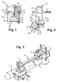
- FIG. 1 represents the vice according to the invention, seen from the front in the left part of the drawing and in section on the right.
- Figure 2 shows the vice of Figure 1 seen laterally and shown mounted on a joint of the type described in European patent application No. 0 700 664 on behalf of the licensee.
- Figure 3 is a perspective view of the entire fixator according to the invention.
- the vice 10 shown in Figure 1 is conventionally constituted by an upper jaw 20 and a lower jaw 30 connected by a central screw of tightening 40. These jaws 20 and 30 have series of parallel grooves 21 and 31 for bone sheets 3.
- the upper jaw 20 further comprises two wings 22 and 23 for relative positioning of the jaws and a central passage 24 in which the clamping screw 40 passes freely.
- the lower jaw 30 has a general shape "U" (upside down in the drawing), including legs 32 and 33 are intended to receive a bar 50 whose ends are inserted in a passage 34 practiced in each leg, and fixed by means of a pin 35 intended to prevent any rotation of the bar.
- the lower jaw 30 also has a passage central 36 intended to cooperate with the screw 40.
- a threaded metal sleeve 37 is interposed between passage 36 and screw 40.
- the jaws 20 and 30 forming the clamp 10 for clamping sheets 3 the lower jaw 30 presenting the bar 50 intended for fixing a joint 60.
- the latter includes a first pair of jaws 61 clamped on a spreader bar and a second pair of jaws 62 tightened on the bar 50, these pairs of jaws can be oriented relative to a central axis constituted by the clamping screw 63 which constitutes the axis of jaw rotation.
- the method of positioning the fixative described so far is involves inserting pairs of plugs into bone fragments on either side of the fracture, at tighten the plugs in the vices, to mount the joints on the vices and on a stiffening bar, before final adjustment of the position of the bone fragments thanks to the combination of the movements of joint rotation or in other words positioning of the stiffening bar in relation to sheets.
- the bars 50 and the bar 9 have the same diameter, which allows a greater freedom in positioning components and to limit as much as possible the size and the parts protrusion of the jaws and joints, while allowing easy access to clamping parts.
Landscapes
- Health & Medical Sciences (AREA)
- Orthopedic Medicine & Surgery (AREA)
- Life Sciences & Earth Sciences (AREA)
- Surgery (AREA)
- Biomedical Technology (AREA)
- Engineering & Computer Science (AREA)
- Nuclear Medicine, Radiotherapy & Molecular Imaging (AREA)
- Heart & Thoracic Surgery (AREA)
- Medical Informatics (AREA)
- Molecular Biology (AREA)
- Animal Behavior & Ethology (AREA)
- General Health & Medical Sciences (AREA)
- Public Health (AREA)
- Veterinary Medicine (AREA)
- Surgical Instruments (AREA)
Description
- deux groupes de fiches insérées respectivement de part et d'autre de la fracture,
- deux étaux de fixation des fiches,
- deux articulations assurant l'orientation des étaux par rapport à une barre de rigidification.
- des articulations 7 et 8 par rapport à l'axe de la barre 9,
- des paires de mâchoires de chaque articulation 7 ou 8 sur leur axe de serrage 63,
- des articulations 7 et 8 par rapport à la barrette de chaque étau 5 ou 6.
Claims (4)
- Fixateur externe comportant au moinscaractérisé par le fait que l'une des mâchoires de chaque étau comporte une barrette cylindrique (50) destinée à coopérer avec une articulation, ladite barrette (50) étant parallèle au plan des fiches (3) et perpendiculaire par rapport à l'axe de celles-ci.deux groupes de fiches (3,4) insérées respectivement de part et d'autre de la fracture,deux étaux (5, 6 ; 10) de fixation des fiches,deux articulations (7,8 ; 60) assurant l'orientation des étaux par rapport à une barre de rigidification (9),
- Fixateur selon la revendication 1, caractérisé par le fait que chaque étau comporte une mâchoire (30) en forme de U dont les jambages (32, 33) comportent deux ouvertures (34) vis-à-vis, dans lesquelles sont insérées les extrémités de la barrette (50).
- Fixateur selon la revendication 2, caractérisé par le fait que ledit jambage (32, 33) comporte en outre un passage pour un moyen de blocage (35) de la barrette (50) en rotation.
- Fixateur selon la revendication 1 caractérisé par le fait que les mâchoires 20 et 30 de l'étau sont en matériaux plastiques renforcés.
Applications Claiming Priority (4)
| Application Number | Priority Date | Filing Date | Title |
|---|---|---|---|
| CH120696 | 1996-05-10 | ||
| CH01206/96A CH691568A5 (fr) | 1996-05-10 | 1996-05-10 | Fixateur externe. |
| CH1206/96 | 1996-05-10 | ||
| US08/843,420 US5891144A (en) | 1996-05-10 | 1997-04-15 | External fixator |
Publications (2)
| Publication Number | Publication Date |
|---|---|
| EP0806185A1 EP0806185A1 (fr) | 1997-11-12 |
| EP0806185B1 true EP0806185B1 (fr) | 2002-11-27 |
Family
ID=25686989
Family Applications (1)
| Application Number | Title | Priority Date | Filing Date |
|---|---|---|---|
| EP97810280A Expired - Lifetime EP0806185B1 (fr) | 1996-05-10 | 1997-05-05 | Fixateur externe |
Country Status (4)
| Country | Link |
|---|---|
| US (1) | US5891144A (fr) |
| EP (1) | EP0806185B1 (fr) |
| JP (1) | JP3085919B2 (fr) |
| CA (1) | CA2204449C (fr) |
Families Citing this family (68)
| Publication number | Priority date | Publication date | Assignee | Title |
|---|---|---|---|---|
| DE59813925D1 (en) * | 1998-05-19 | 2007-04-12 | Synthes Gmbh | Backe für monolaterales externes fixationssystem für traumatologie und orthopädie |
| US6423069B1 (en) * | 1999-03-23 | 2002-07-23 | Synthes (Usa) | Orthopedic system having detachable bone anchors |
| JP2001037767A (ja) * | 1999-08-02 | 2001-02-13 | Kyowa Tokei Kogyo Kk | 骨調整具 |
| US6277119B1 (en) | 1999-10-21 | 2001-08-21 | Electro-Biology, Inc. | External fixation system |
| US6616664B2 (en) | 1999-10-21 | 2003-09-09 | Ebi L.P. | Clamp assembly for an external fixation system |
| US6613049B2 (en) * | 2000-02-02 | 2003-09-02 | Robert A. Winquist | Adjustable bone stabilizing frame system |
| DE50008366D1 (de) * | 2000-05-31 | 2004-11-25 | Stratec Medical Ag Oberdorf | Vorrichtung zur positionierung eines chirurgischen instrumentes |
| US6565564B2 (en) * | 2000-12-14 | 2003-05-20 | Synthes U.S.A. | Multi-pin clamp and rod attachment |
| US6482206B2 (en) | 2001-02-22 | 2002-11-19 | Biomet, Inc. | Method and apparatus for external fixation of bones |
| US6872210B2 (en) * | 2001-02-23 | 2005-03-29 | James P. Hearn | Sternum fixation device |
| US7261713B2 (en) * | 2001-10-09 | 2007-08-28 | Synthes (Usa) | Adjustable fixator |
| US6709433B1 (en) | 2001-12-20 | 2004-03-23 | Biomet, Inc. | Bridging/non-bridging external bone fixator |
| US7004943B2 (en) * | 2002-02-04 | 2006-02-28 | Smith & Nephew, Inc. | Devices, systems, and methods for placing and positioning fixation elements in external fixation systems |
| US7048735B2 (en) | 2002-02-04 | 2006-05-23 | Smith & Nephew | External fixation system |
| WO2003105704A1 (fr) * | 2002-06-14 | 2003-12-24 | Smith & Nephew, Inc. | Dispositifs et procedes pour placer des elements de fixation externes |
| JP4490821B2 (ja) * | 2002-09-17 | 2010-06-30 | エクストラオルト インコーポレイテッド | 片側骨固定器 |
| US8419732B2 (en) * | 2002-11-14 | 2013-04-16 | Sixfix, Inc. | Method for using a fixator device |
| AU2003295521A1 (en) * | 2002-11-15 | 2004-06-15 | Amei Technologies Inc. | Apparatus and method for maintaining bones in a healing position |
| US7608074B2 (en) * | 2003-01-10 | 2009-10-27 | Smith & Nephew, Inc. | External fixation apparatus and method |
| EP1522266A1 (fr) * | 2003-10-06 | 2005-04-13 | Stryker Trauma SA | Elements de fixation externe |
| JP5394639B2 (ja) * | 2004-04-19 | 2014-01-22 | ジンテーズ ゲゼルシャフト ミト ベシュレンクテル ハフツング | 医療技術的装置のためのx線透過材料からなる弾性素子 |
| ATE375760T1 (de) * | 2004-08-20 | 2007-11-15 | Stryker Trauma Sa | Klemmelement zum klemmen von mehreren stabförmigen elementen |
| US20060235383A1 (en) * | 2005-03-07 | 2006-10-19 | Shane Hollawell | External fixator |
| US8758343B2 (en) | 2005-04-27 | 2014-06-24 | DePuy Synthes Products, LLC | Bone fixation apparatus |
| GB2427141B (en) * | 2005-06-13 | 2010-12-22 | Intelligent Orthopaedics Ltd | Fixator |
| US8523858B2 (en) | 2005-06-21 | 2013-09-03 | DePuy Synthes Products, LLC | Adjustable fixation clamp and method |
| US7708736B2 (en) * | 2006-02-22 | 2010-05-04 | Extraortho, Inc. | Articulation apparatus for external fixation device |
| DE602006004168D1 (de) * | 2006-03-31 | 2009-01-22 | Stryker Trauma Sa | Externes Fixierelement mit einer rauhen, abgetragenen Oberfläche |
| ES2638425T3 (es) * | 2006-05-29 | 2017-10-20 | Stryker European Holdings I, Llc | Elemento de sujecion y pieza de insercion para el mismo |
| ES2471948T3 (es) * | 2006-10-13 | 2014-06-27 | Stryker Trauma Sa | Prevención de reutilización de un dispositivo m�dico |
| US8277448B2 (en) * | 2007-03-07 | 2012-10-02 | Wright Medical Technology, Inc. | External fixation |
| WO2009042836A1 (fr) | 2007-09-27 | 2009-04-02 | Qfx Technologies, Incorporated | Procédé et appareil de clampage pour fixation externe et stabilisation |
| US8506606B2 (en) * | 2008-08-01 | 2013-08-13 | Skeletal Dynamics, Llc | Internal joint stabilizer device, system, and method of use |
| US10327817B2 (en) | 2008-08-01 | 2019-06-25 | Skeletal Dynamics Llc | Internal joint stabilizer device, system and method of use |
| EP2294994B1 (fr) * | 2009-09-11 | 2018-04-04 | Stryker European Holdings I, LLC | Composant de fixation externe |
| WO2012003455A1 (fr) | 2010-07-01 | 2012-01-05 | Extraortho, Inc. | Collier de fixation externe à verrouillage multiple |
| ES2541831T3 (es) | 2010-10-07 | 2015-07-27 | Stryker Trauma Sa | Elemento de acoplamiento para un dispositivo de fijación externo |
| US8734446B2 (en) | 2010-10-12 | 2014-05-27 | Zimmer, Inc. | External fixation surgical clamp with swivel |
| EP3388007A3 (fr) | 2010-10-12 | 2019-02-20 | Zimmer, Inc. | Agencement de pince de fixation externe à verrou unique |
| US8728078B2 (en) | 2010-11-04 | 2014-05-20 | Zimmer, Inc. | Clamping assembly with links |
| EP2648633B1 (fr) | 2010-12-09 | 2016-05-18 | Zimmer, Inc. | Mâchoire actionnée par came pour pinces de fixation externes |
| EP2648634B1 (fr) | 2010-12-09 | 2016-05-18 | Zimmer, Inc. | Verrou rotatif pour clamps de fixation externe |
| ES2540256T3 (es) | 2010-12-14 | 2015-07-09 | Stryker Trauma Sa | Pinza de fijación |
| EP2465454B1 (fr) | 2010-12-14 | 2015-04-08 | Stryker Trauma SA | Fixation avec mollette |
| USD683461S1 (en) | 2010-12-14 | 2013-05-28 | Stryker Trauma Sa | Hinge coupling |
| ES2540276T3 (es) | 2010-12-14 | 2015-07-09 | Stryker Trauma Sa | Pinza de fijación |
| USD704840S1 (en) | 2010-12-14 | 2014-05-13 | Stryker Trauma Sa | Hinge coupling |
| USD720853S1 (en) | 2010-12-14 | 2015-01-06 | Stryker Trauma Sa | Fixation clamp |
| WO2012158698A1 (fr) * | 2011-05-17 | 2012-11-22 | Extraortho, Inc. | Système de serrage à fixation externe utilisant un mécanisme de déclenchement et de l'énergie de ressort emmagasinée |
| USD663030S1 (en) | 2011-06-14 | 2012-07-03 | Styker Trauma SA | Fixation clamp |
| USD682426S1 (en) | 2011-06-14 | 2013-05-14 | Stryker Trauma Sa | Fixation clamp |
| US9924969B2 (en) | 2012-09-04 | 2018-03-27 | Zimmer, Inc. | External fixation |
| US9301782B2 (en) | 2012-09-04 | 2016-04-05 | Zimmer, Inc. | External fixation |
| US9770272B2 (en) | 2012-12-12 | 2017-09-26 | Wright Medical Technology, Inc. | Orthopedic compression/distraction device |
| US9301783B2 (en) | 2013-01-23 | 2016-04-05 | Fixx Orthopedics, LLC | Orthopedic external fixation device |
| US9408635B2 (en) | 2013-03-15 | 2016-08-09 | Wright Medical Technology, Inc. | External fixation |
| US20140276820A1 (en) | 2013-03-15 | 2014-09-18 | Biomet C.V. | External fixation system |
| ITMI20130407A1 (it) * | 2013-03-18 | 2014-09-19 | Orthofix Srl | Dispositivo di fissazione esterna |
| US9962188B2 (en) | 2013-10-29 | 2018-05-08 | Cardinal Health 247. Inc. | External fixation system and methods of use |
| US9962187B2 (en) | 2014-08-11 | 2018-05-08 | Zimmer, Inc. | External fixation |
| WO2016138220A1 (fr) * | 2015-02-27 | 2016-09-01 | Thomas Gerold | Dispositif de fixation externe orthopédique |
| WO2016205128A2 (fr) | 2015-06-17 | 2016-12-22 | Nathan Erickson | Système de fixation de cheville |
| US10799226B2 (en) * | 2015-07-15 | 2020-10-13 | Warsaw Orthopedic, Inc. | Surgical adaptor and method |
| US10136919B2 (en) * | 2015-12-03 | 2018-11-27 | Globus Medical, Inc. | External fixator assembly |
| FR3046725B1 (fr) | 2016-01-15 | 2021-09-10 | Gexfix Sa | Dispositif de fixation orthopedique |
| TWI572318B (zh) * | 2016-04-26 | 2017-03-01 | 長庚醫療財團法人林口長庚紀念醫院 | 克氏鋼釘固定結構 |
| KR102030140B1 (ko) * | 2019-04-30 | 2019-11-08 | (주)이노메디텍 | 골절치료용 체외고정장치의 핀 클램프 |
| CN114993636B (zh) * | 2022-04-20 | 2023-04-11 | 海南大学 | 一种用于简支梁力学性能试验的可调节固定铰支座 |
Citations (1)
| Publication number | Priority date | Publication date | Assignee | Title |
|---|---|---|---|---|
| EP0700664A1 (fr) * | 1994-09-06 | 1996-03-13 | Jaquet Orthopedie S.A. | Articulation pour composants d'un fixateur externe |
Family Cites Families (7)
| Publication number | Priority date | Publication date | Assignee | Title |
|---|---|---|---|---|
| DE2745504A1 (de) * | 1977-10-10 | 1979-04-19 | Erich Strickle | Vorrichtung zur ruhigstellung oder stuetzung von gliedmassen von menschen und tieren |
| DE3614305A1 (de) * | 1986-04-29 | 1987-11-12 | Baehr Geb Green Judith M | Aeusserlich anwendbarer fixateur |
| FR2616059A1 (fr) * | 1987-06-05 | 1988-12-09 | Sorem Soc Realisa Elect Mec | Appareil pour la reduction et/ou la contention d'un os fracture |
| CH678485A5 (fr) * | 1988-12-15 | 1991-09-30 | Jaquet Orthopedie | |
| US5207676A (en) * | 1989-02-27 | 1993-05-04 | Jaquet Orthopedie S.A. | External fixator with controllable damping |
| CH679448A5 (fr) * | 1989-02-27 | 1992-02-28 | Jaquet Orthopedie | |
| CH684928A5 (fr) * | 1990-12-10 | 1995-02-15 | Jaquet Orthopedie | Fixateur externe. |
-
1997
- 1997-04-15 US US08/843,420 patent/US5891144A/en not_active Expired - Lifetime
- 1997-05-05 EP EP97810280A patent/EP0806185B1/fr not_active Expired - Lifetime
- 1997-05-05 CA CA002204449A patent/CA2204449C/fr not_active Expired - Lifetime
- 1997-05-09 JP JP09119902A patent/JP3085919B2/ja not_active Expired - Lifetime
Patent Citations (1)
| Publication number | Priority date | Publication date | Assignee | Title |
|---|---|---|---|---|
| EP0700664A1 (fr) * | 1994-09-06 | 1996-03-13 | Jaquet Orthopedie S.A. | Articulation pour composants d'un fixateur externe |
Also Published As
| Publication number | Publication date |
|---|---|
| JP3085919B2 (ja) | 2000-09-11 |
| US5891144A (en) | 1999-04-06 |
| EP0806185A1 (fr) | 1997-11-12 |
| JPH1057397A (ja) | 1998-03-03 |
| CA2204449C (fr) | 2000-10-17 |
| CA2204449A1 (fr) | 1997-11-10 |
Similar Documents
| Publication | Publication Date | Title |
|---|---|---|
| EP0806185B1 (fr) | Fixateur externe | |
| EP0700664B1 (fr) | Articulation pour composants d'un fixateur externe | |
| EP0490812B1 (fr) | Fixateur externe pour l'ostéosynthèse | |
| EP0385929B1 (fr) | Fixateur externe avec amortissement contrôlable | |
| CH664079A5 (fr) | Element d'arceau et fixateur externe pour osteosynthese et osteoplastie. | |
| CH630798A5 (fr) | Fixateur externe pour osteosynthese. | |
| KR20030076582A (ko) | 로드 및 구형 대칭 스크류 헤드를 고정하는 장치 | |
| EP0420813A1 (fr) | Dispositif d'articulation et de blocage relatif de deux pièces | |
| FR2697742A1 (fr) | Dispositif d'ostéosynthèse pour consolidation rachidienne. | |
| FR2499400A1 (fr) | Fixateur perfectionne pour fractures complexes, et notamment du type epiphysaire | |
| FR2615095A1 (fr) | Instrumentation d'osteosynthese pour la correction de scolioses lombaires par voie posterieure | |
| EP0641548A1 (fr) | Vis pour fixateur lombo-sacre | |
| WO2007036657A1 (fr) | Systeme de fixation vertebrale | |
| CH678485A5 (fr) | ||
| FR2761876A1 (fr) | Instrumentation d'osteosynthese lombaire pour la correction du spondylolisthesis par voie posterieure | |
| FR2687561A1 (fr) | Dispositif de redressement, de fixation, de compression et d'elongation de vertebres cervicales. | |
| FR2827150A1 (fr) | Dispositif de fixation auto-retentif | |
| WO1990011727A1 (fr) | Fixateur pour intervention orthopedique | |
| FR2983696A1 (fr) | Systeme de pincement osseux | |
| FR2714590A1 (fr) | Dispositif dénommé fixateur transverse permettant de solidariser les tiges dans les opérations du rachis. | |
| CH691568A5 (fr) | Fixateur externe. | |
| EP0256984B1 (fr) | Fixateur externe à biocompression pour ostéosynthèse | |
| FR2665353A1 (fr) | Fixateur externe pour la reduction des fractures du poignet. | |
| FR2745708A1 (fr) | Dispositif de liaison rachidienne transverse | |
| EP1304969B1 (fr) | Plaque d'osteosynthese |
Legal Events
| Date | Code | Title | Description |
|---|---|---|---|
| PUAI | Public reference made under article 153(3) epc to a published international application that has entered the european phase |
Free format text: ORIGINAL CODE: 0009012 |
|
| AK | Designated contracting states |
Kind code of ref document: A1 Designated state(s): AT BE CH DE DK ES FI FR GB GR IE IT LI NL PT SE |
|
| 17P | Request for examination filed |
Effective date: 19980204 |
|
| 17Q | First examination report despatched |
Effective date: 20001113 |
|
| GRAG | Despatch of communication of intention to grant |
Free format text: ORIGINAL CODE: EPIDOS AGRA |
|
| GRAG | Despatch of communication of intention to grant |
Free format text: ORIGINAL CODE: EPIDOS AGRA |
|
| GRAH | Despatch of communication of intention to grant a patent |
Free format text: ORIGINAL CODE: EPIDOS IGRA |
|
| GRAH | Despatch of communication of intention to grant a patent |
Free format text: ORIGINAL CODE: EPIDOS IGRA |
|
| GRAA | (expected) grant |
Free format text: ORIGINAL CODE: 0009210 |
|
| RAP1 | Party data changed (applicant data changed or rights of an application transferred) |
Owner name: STRYKER TRAUMA S.A. |
|
| AK | Designated contracting states |
Kind code of ref document: B1 Designated state(s): AT BE CH DE DK ES FI FR GB GR IE IT LI NL PT SE |
|
| PG25 | Lapsed in a contracting state [announced via postgrant information from national office to epo] |
Ref country code: NL Free format text: LAPSE BECAUSE OF FAILURE TO SUBMIT A TRANSLATION OF THE DESCRIPTION OR TO PAY THE FEE WITHIN THE PRESCRIBED TIME-LIMIT Effective date: 20021127 Ref country code: IE Free format text: LAPSE BECAUSE OF FAILURE TO SUBMIT A TRANSLATION OF THE DESCRIPTION OR TO PAY THE FEE WITHIN THE PRESCRIBED TIME-LIMIT Effective date: 20021127 Ref country code: GR Free format text: LAPSE BECAUSE OF FAILURE TO SUBMIT A TRANSLATION OF THE DESCRIPTION OR TO PAY THE FEE WITHIN THE PRESCRIBED TIME-LIMIT Effective date: 20021127 Ref country code: FI Free format text: LAPSE BECAUSE OF FAILURE TO SUBMIT A TRANSLATION OF THE DESCRIPTION OR TO PAY THE FEE WITHIN THE PRESCRIBED TIME-LIMIT Effective date: 20021127 Ref country code: AT Free format text: LAPSE BECAUSE OF FAILURE TO SUBMIT A TRANSLATION OF THE DESCRIPTION OR TO PAY THE FEE WITHIN THE PRESCRIBED TIME-LIMIT Effective date: 20021127 |
|
| REF | Corresponds to: |
Ref document number: 228337 Country of ref document: AT Date of ref document: 20021215 Kind code of ref document: T |
|
| REG | Reference to a national code |
Ref country code: GB Ref legal event code: FG4D Free format text: NOT ENGLISH |
|
| REG | Reference to a national code |
Ref country code: CH Ref legal event code: EP |
|
| REG | Reference to a national code |
Ref country code: IE Ref legal event code: FG4D Free format text: FRENCH |
|
| REF | Corresponds to: |
Ref document number: 69717343 Country of ref document: DE Date of ref document: 20030109 |
|
| GBT | Gb: translation of ep patent filed (gb section 77(6)(a)/1977) |
Effective date: 20021219 |
|
| PG25 | Lapsed in a contracting state [announced via postgrant information from national office to epo] |
Ref country code: SE Free format text: LAPSE BECAUSE OF FAILURE TO SUBMIT A TRANSLATION OF THE DESCRIPTION OR TO PAY THE FEE WITHIN THE PRESCRIBED TIME-LIMIT Effective date: 20030227 Ref country code: PT Free format text: LAPSE BECAUSE OF FAILURE TO SUBMIT A TRANSLATION OF THE DESCRIPTION OR TO PAY THE FEE WITHIN THE PRESCRIBED TIME-LIMIT Effective date: 20030227 Ref country code: DK Free format text: LAPSE BECAUSE OF FAILURE TO SUBMIT A TRANSLATION OF THE DESCRIPTION OR TO PAY THE FEE WITHIN THE PRESCRIBED TIME-LIMIT Effective date: 20030227 |
|
| NLV1 | Nl: lapsed or annulled due to failure to fulfill the requirements of art. 29p and 29m of the patents act | ||
| REG | Reference to a national code |
Ref country code: ES Ref legal event code: FG2A Ref document number: 2185892 Country of ref document: ES Kind code of ref document: T3 |
|
| PG25 | Lapsed in a contracting state [announced via postgrant information from national office to epo] |
Ref country code: BE Free format text: LAPSE BECAUSE OF NON-PAYMENT OF DUE FEES Effective date: 20030531 |
|
| REG | Reference to a national code |
Ref country code: IE Ref legal event code: FD4D Ref document number: 0806185E Country of ref document: IE |
|
| PLBE | No opposition filed within time limit |
Free format text: ORIGINAL CODE: 0009261 |
|
| STAA | Information on the status of an ep patent application or granted ep patent |
Free format text: STATUS: NO OPPOSITION FILED WITHIN TIME LIMIT |
|
| 26N | No opposition filed |
Effective date: 20030828 |
|
| BERE | Be: lapsed |
Owner name: S.A. *STRYKER TRAUMA Effective date: 20030531 |
|
| PGFP | Annual fee paid to national office [announced via postgrant information from national office to epo] |
Ref country code: CH Payment date: 20140425 Year of fee payment: 18 |
|
| REG | Reference to a national code |
Ref country code: CH Ref legal event code: PL |
|
| PG25 | Lapsed in a contracting state [announced via postgrant information from national office to epo] |
Ref country code: LI Free format text: LAPSE BECAUSE OF NON-PAYMENT OF DUE FEES Effective date: 20150531 Ref country code: CH Free format text: LAPSE BECAUSE OF NON-PAYMENT OF DUE FEES Effective date: 20150531 |
|
| REG | Reference to a national code |
Ref country code: FR Ref legal event code: PLFP Year of fee payment: 20 |
|
| REG | Reference to a national code |
Ref country code: DE Ref legal event code: R082 Ref document number: 69717343 Country of ref document: DE Representative=s name: GILLE HRABAL, DE Ref country code: DE Ref legal event code: R081 Ref document number: 69717343 Country of ref document: DE Owner name: STRYKER EUROPEAN HOLDINGS I, LLC (N.D. GES. D., US Free format text: FORMER OWNER: STRYKER TRAUMA S.A., SELZACH, CH Ref country code: DE Ref legal event code: R081 Ref document number: 69717343 Country of ref document: DE Owner name: STRYKER EUROPEAN HOLDINGS V, LLC (N.D. GES. D., US Free format text: FORMER OWNER: STRYKER TRAUMA S.A., SELZACH, CH |
|
| PGFP | Annual fee paid to national office [announced via postgrant information from national office to epo] |
Ref country code: GB Payment date: 20160504 Year of fee payment: 20 Ref country code: ES Payment date: 20160414 Year of fee payment: 20 Ref country code: DE Payment date: 20160426 Year of fee payment: 20 |
|
| PGFP | Annual fee paid to national office [announced via postgrant information from national office to epo] |
Ref country code: IT Payment date: 20160524 Year of fee payment: 20 Ref country code: FR Payment date: 20160412 Year of fee payment: 20 |
|
| REG | Reference to a national code |
Ref country code: FR Ref legal event code: TP Owner name: STRYKER EUROPEAN HOLDINGS I, LLC, US Effective date: 20161003 |
|
| REG | Reference to a national code |
Ref country code: GB Ref legal event code: 732E Free format text: REGISTERED BETWEEN 20161013 AND 20161019 |
|
| REG | Reference to a national code |
Ref country code: ES Ref legal event code: PC2A Owner name: STRYKER EUROPEAN HOLDINGS I, LLC Effective date: 20161111 |
|
| REG | Reference to a national code |
Ref country code: DE Ref legal event code: R082 Ref document number: 69717343 Country of ref document: DE Representative=s name: GILLE HRABAL, DE Ref country code: DE Ref legal event code: R081 Ref document number: 69717343 Country of ref document: DE Owner name: STRYKER EUROPEAN HOLDINGS I, LLC (N.D. GES. D., US Free format text: FORMER OWNER: STRYKER EUROPEAN HOLDINGS V, LLC (N.D. GES. D. STAATES DELAWARE), KALAMAZOO, MICH., US |
|
| REG | Reference to a national code |
Ref country code: DE Ref legal event code: R071 Ref document number: 69717343 Country of ref document: DE |
|
| REG | Reference to a national code |
Ref country code: GB Ref legal event code: PE20 Expiry date: 20170504 |
|
| PG25 | Lapsed in a contracting state [announced via postgrant information from national office to epo] |
Ref country code: GB Free format text: LAPSE BECAUSE OF EXPIRATION OF PROTECTION Effective date: 20170504 |
|
| REG | Reference to a national code |
Ref country code: ES Ref legal event code: FD2A Effective date: 20180508 |
|
| PG25 | Lapsed in a contracting state [announced via postgrant information from national office to epo] |
Ref country code: ES Free format text: LAPSE BECAUSE OF EXPIRATION OF PROTECTION Effective date: 20170506 |