EP0805922B1 - Steuersystem für eine flugzeugflüssigkeitspumpe - Google Patents
Steuersystem für eine flugzeugflüssigkeitspumpe Download PDFInfo
- Publication number
- EP0805922B1 EP0805922B1 EP96909701A EP96909701A EP0805922B1 EP 0805922 B1 EP0805922 B1 EP 0805922B1 EP 96909701 A EP96909701 A EP 96909701A EP 96909701 A EP96909701 A EP 96909701A EP 0805922 B1 EP0805922 B1 EP 0805922B1
- Authority
- EP
- European Patent Office
- Prior art keywords
- pump
- speed
- motor
- displacement
- hydraulic
- Prior art date
- Legal status (The legal status is an assumption and is not a legal conclusion. Google has not performed a legal analysis and makes no representation as to the accuracy of the status listed.)
- Expired - Lifetime
Links
- 230000004044 response Effects 0.000 claims abstract description 19
- 238000006073 displacement reaction Methods 0.000 claims description 46
- 238000000034 method Methods 0.000 claims description 14
- 230000007423 decrease Effects 0.000 claims description 6
- 230000008859 change Effects 0.000 claims description 5
- 239000012530 fluid Substances 0.000 claims description 3
- 230000003247 decreasing effect Effects 0.000 claims 1
- 238000010586 diagram Methods 0.000 description 8
- 230000006698 induction Effects 0.000 description 8
- 230000001052 transient effect Effects 0.000 description 8
- 238000013459 approach Methods 0.000 description 4
- 230000008901 benefit Effects 0.000 description 3
- 230000009471 action Effects 0.000 description 2
- 230000001143 conditioned effect Effects 0.000 description 2
- 230000000994 depressogenic effect Effects 0.000 description 2
- 238000005461 lubrication Methods 0.000 description 2
- 230000007246 mechanism Effects 0.000 description 2
- 230000001172 regenerating effect Effects 0.000 description 2
- 230000015556 catabolic process Effects 0.000 description 1
- 238000005094 computer simulation Methods 0.000 description 1
- 238000007796 conventional method Methods 0.000 description 1
- 238000006731 degradation reaction Methods 0.000 description 1
- 230000001419 dependent effect Effects 0.000 description 1
- 238000001746 injection moulding Methods 0.000 description 1
- 230000009467 reduction Effects 0.000 description 1
- 238000004088 simulation Methods 0.000 description 1
- 239000000243 solution Substances 0.000 description 1
Images


Classifications
-
- F—MECHANICAL ENGINEERING; LIGHTING; HEATING; WEAPONS; BLASTING
- F04—POSITIVE - DISPLACEMENT MACHINES FOR LIQUIDS; PUMPS FOR LIQUIDS OR ELASTIC FLUIDS
- F04B—POSITIVE-DISPLACEMENT MACHINES FOR LIQUIDS; PUMPS
- F04B1/00—Multi-cylinder machines or pumps characterised by number or arrangement of cylinders
- F04B1/12—Multi-cylinder machines or pumps characterised by number or arrangement of cylinders having cylinder axes coaxial with, or parallel or inclined to, main shaft axis
- F04B1/26—Control
- F04B1/30—Control of machines or pumps with rotary cylinder blocks
- F04B1/32—Control of machines or pumps with rotary cylinder blocks by varying the relative positions of a swash plate and a cylinder block
- F04B1/324—Control of machines or pumps with rotary cylinder blocks by varying the relative positions of a swash plate and a cylinder block by changing the inclination of the swash plate
-
- F—MECHANICAL ENGINEERING; LIGHTING; HEATING; WEAPONS; BLASTING
- F04—POSITIVE - DISPLACEMENT MACHINES FOR LIQUIDS; PUMPS FOR LIQUIDS OR ELASTIC FLUIDS
- F04B—POSITIVE-DISPLACEMENT MACHINES FOR LIQUIDS; PUMPS
- F04B49/00—Control, e.g. of pump delivery, or pump pressure of, or safety measures for, machines, pumps, or pumping installations, not otherwise provided for, or of interest apart from, groups F04B1/00 - F04B47/00
- F04B49/06—Control using electricity
-
- F—MECHANICAL ENGINEERING; LIGHTING; HEATING; WEAPONS; BLASTING
- F04—POSITIVE - DISPLACEMENT MACHINES FOR LIQUIDS; PUMPS FOR LIQUIDS OR ELASTIC FLUIDS
- F04B—POSITIVE-DISPLACEMENT MACHINES FOR LIQUIDS; PUMPS
- F04B2201/00—Pump parameters
- F04B2201/12—Parameters of driving or driven means
- F04B2201/1205—Position of a non-rotating inclined plate
- F04B2201/12051—Angular position
-
- F—MECHANICAL ENGINEERING; LIGHTING; HEATING; WEAPONS; BLASTING
- F04—POSITIVE - DISPLACEMENT MACHINES FOR LIQUIDS; PUMPS FOR LIQUIDS OR ELASTIC FLUIDS
- F04B—POSITIVE-DISPLACEMENT MACHINES FOR LIQUIDS; PUMPS
- F04B2203/00—Motor parameters
- F04B2203/02—Motor parameters of rotating electric motors
- F04B2203/0201—Current
-
- F—MECHANICAL ENGINEERING; LIGHTING; HEATING; WEAPONS; BLASTING
- F04—POSITIVE - DISPLACEMENT MACHINES FOR LIQUIDS; PUMPS FOR LIQUIDS OR ELASTIC FLUIDS
- F04B—POSITIVE-DISPLACEMENT MACHINES FOR LIQUIDS; PUMPS
- F04B2207/00—External parameters
- F04B2207/01—Load in general
-
- Y—GENERAL TAGGING OF NEW TECHNOLOGICAL DEVELOPMENTS; GENERAL TAGGING OF CROSS-SECTIONAL TECHNOLOGIES SPANNING OVER SEVERAL SECTIONS OF THE IPC; TECHNICAL SUBJECTS COVERED BY FORMER USPC CROSS-REFERENCE ART COLLECTIONS [XRACs] AND DIGESTS
- Y10—TECHNICAL SUBJECTS COVERED BY FORMER USPC
- Y10S—TECHNICAL SUBJECTS COVERED BY FORMER USPC CROSS-REFERENCE ART COLLECTIONS [XRACs] AND DIGESTS
- Y10S60/00—Power plants
- Y10S60/911—Fluid motor system incorporating electrical system
Definitions
- This invention relates to aircraft electrically driven hydraulic pumps and more particularly to control systems for electrically driven hydraulic pumps. Specifically, the invention relates to a hydraulic supply system as defined in the pre-characterizing portion of claim 1 and a method for operating such system as defined in the pre-characterizing portion of claim 5. Such a system and method of operation are known from US-A-5 141 402.
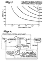
- FIG. 1 indicates the approximate portion of the hydraulic pump speed vs. displacement curve on which the conventional system operates.
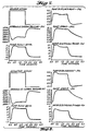
- FIG, 2 shows a typical transient response for this type of system.
- pump displacement and flow are increased by the swashplate to maintain the system pressure.
- Pump speed, and the electrical power consumed by the motor are also displayed.
- the swashplate reduces the pump displacement and flow to maintain system pressure near the reference value of approximately 20.7 MPa (3,000 psi).
- the induction motor which drives the hydraulic pump is continually supplied from a 115 VAC, 400 Hz source.
- the induction motor and pump operate at essentially a constant speed, only slightly changed by the system loading. Approximately 80 to 90% of the time the motor-pumps are minimally loaded. Therefore, the induction motor operates at a point of low efficiency, and the hydraulic pump turns at a high speed (typically about 6,000 RPM) which results in high noise and reduced pump life.
- Induction motor starting currents range from four to six times rated current until the motor comes up to speed, causing a significant depression in the system voltage.
- relays are incorporated into the electrical system to allow staggered starting of these electric motor-pumps from a single source. These additional relays have a negative impact on system reliability and maintainability.
- This known hydraulic supply system is described for use in stationary hydraulic systems, like e.g. a system for operating injection molding machinery.
- This prior art document does not give any indication about the way and order in which the displacement of the pump and the speed of the electric motor are varied in response to the varying demand.
- the invention now has for his object to provide an improved hydraulic supply system providing fast dynamic response during both load application and removal.
- this is achieved in a hydraulic supply system having the features of the pre-characterizing portion of claim 1, in that said control circuit means are arranged for changing the speed of the electric motor in response to a change in system demand at a slower rate than that at which the displacement of the pump is varied.
- the hydraulic supply system may respond vary fast to variations in slow demand.
- the motor is driven at reduced speed when demand is low to extend the motor and pump lives.
- the variable displacement pump permits the use of a control method which provides rapid response to sudden changes in demand.
- the present invention since it utilizes a motor-controller would further be capable of soft starting the motor-pump hence avoiding the above high starting currents. Moreover, a favored feature of the invention is its compatibility with a variable frequency power system.
- the invention further has for its object to provide an improved method of operating a hydraulic supply system.
- the invention provides a method having the features of the pre-characterizing portion of claim 5, that is characterized in that the speed of the motor is reduced at a slower rate than the displacement of the pump.
- a suitable control approach would involve operating the motor-pump at a reduced speed when it is lightly loaded (low-flow conditions). This would increase the motor efficiency and pump life while reducing pump noise.
- the electric motor-pump would operate at higher speeds to meet the system requirements.
- the speed increase would be due to a change in the conditioned power supplied to the motor by the motor controller.
- the Fixed Displacement Hydraulic Pump/Variable Speed Motor describes a control technique using a fixed displacement hydraulic pump with a variable speed motor.
- the Variable Displacement Hydraulic Pump/Variable Speed Motor describes first and second embodiments of the proposed control technique using a variable displacement pump and a variable speed motor. Comparison of these methods shows that the fixed-displacement pump/variable-speed motor has significant operational problems, while either version of the variable-displacement pump/variable-speed motor offers the best solution.
- FIG. 3 indicates the portion of the hydraulic pump speed vs. displacement curve on which this system would operate. This could be made to satisfy the steady-state flow requirements.
- this approach has some serious problems as described below.
- the first item of concern is that operating a fixed displacement pump into a fixed pressure system will require the electric motor to supply rated torque, hence, to draw rated current at all times. This may result in excessive heat and stress in the motor and its controller.
- a second item of concern is that when very low flow is required by the system the motor speed would be very low ( ⁇ 5-10%). As a result, hydraulic fluid may not provide enough wetness to the hydraulic pump, preventing the buildup of a film thick enough for adequate lubrication. This may cause degradation of the pumps life and operational characteristics.
- a further problem related to this type of control occurs when a rapid decrease in flow is commanded by the system. This may be achieved by quickly slowing the motor-pump combination. However, this represents a significant reduction of the motor-pumps kinetic energy in a short amount of time. This rotational energy is converted to regenerative electrical form which then flows into the motor controller. This stresses components in the motor controller which may require an increase in its size/weight or result in component failure.
- Control system embodiments according to the proposed method involve a combination of a variable displacement pump and a variable speed motor.
- a motor controller is again required to control the speed of the motor, however, the flow is also a function of swashplate position which is not fixed.
- FIGS. 4 and 5 Block diagrams for the first and second embodiments of the present control system are shown in FIGS. 4 and 5 respectively.
- Swashplate displacement is used as an element in the feedback system for the first embodiment in FIG. 4, while the use of motor current in the feedback loop is featured in the second embodiment shown in block diagram in FIG. 5.
- FIG. 6 indicates the portion of the hydraulic pump speed vs. displacement curve on which the system would operate for the first embodiment.
- the speed vs. current curve which would characterize operation of the second embodiment, would have a very similar form.
- the speed/displacement curve shown is illustrative, however for an actual system, the curve is designed in accordance with hydraulic systems requirements and the pumps capability.
- the motor When the hydraulic system requires a high fluid flow, the motor would operate at a high speed and the pumps swashplate position would be at full displacement. System operation would then be confined to the upper right hand region of the curve in FIG. 6.
- the motor speed can be reduced, as can the pump displacement.
- the system would then operate in the lower left portion of the curve in FIG. 6.
- the operation of the motor-pump over the region of low speed has advantages over that for the fixed displacement system herein above described.
- the motor speed is selected so as to provide sufficient wetness to the hydraulic pumps for full-film lubrication.
- the motor current is no longer required to be near its rated value irrespective of the flow requirement as is the case for fixed displacement pumps.
- the swashplate action ensures that the motor-pump would be unloaded during low flow conditions. The motor and pump can therefore operate at a low speed without the motor having to supply a high torque against the system pressure.
- a unique feature of the present control system is that it takes advantage of the variable swashplate to provide fast dynamic response during both load application and removal. This is demonstrated by computer simulation results shown in FIGS. 7 and 8 for the first and second embodiments respectively.
- the motor Prior to load application the motor is assumed to be running at approximately 40% speed, and the swashplate is at a low value of displacement. Operation is in the lower left hand region of FIG. 6.
- the swashplate quickly moves to increase pump flow to maintain system pressure. Meanwhile, the motor speed increases at a somewhat slower rate and eventually reaches an optimum value. Coordination between the motor speed and swashplate position automatically occurs during the motors speed increase to maintain system pressure and flow.
- An added advantage of using a motor controller is that starting an electric motor-pump would no longer result in a high starting current.
- the motor controller would allow the induction motor to accelerate via a "soft startup" with a negligible impact on the electrical power system. Starting of multiple motors from a single source would then not require additional components to control the starting sequence of the motors in the system.
- the present control system embodiments maintain good transient and steady-state system performance.
Landscapes
- Engineering & Computer Science (AREA)
- Mechanical Engineering (AREA)
- General Engineering & Computer Science (AREA)
- Control Of Positive-Displacement Pumps (AREA)
- Control Of Velocity Or Acceleration (AREA)
Claims (5)
- Hydraulikversorgungssystem mit einer Taumelscheibenpumpe mit veränderlicher Auslenkung, einem Elektromotor veränderlicher Geschwindigkeit zum Antrieb der Taumelscheibenpumpe veränderlicher Auslenkung und Steuerschaltmitteln zum Steuern der Geschwindigkeit, bei der der Elektromotor die Pumpe in Abhängigkeit der Anforderung des Versorgungssystems antreibt, dadurch gekennzeichnet, dass die Steuerschaltmittel derart eingerichtet sind, dass sie die Geschwindigkeit des Elektromotors in Abhängigkeit eines Wechsels der Systemanforderung bei einer Rate ändert, die langsamer als die ist, bei der die Auslenkung der Pumpe verändert wird.
- Hydraulikversorgungssystem nach Anspruch 1, dadurch gekennzeichnet , dass die Steuerschaltmittel derart eingerichtet sind, dass sie die Geschwindigkeit des Elektromotors in Abhängigkeit einer Verringerung der Systemanforderung bei einer Rate verringern, die langsamer ist als die, bei der die Geschwindigkeit des Elektromotors in Abhängigkeit einer Zunahme der Systemanforderung erhöht wird.
- Hydraulikversorgungssystem nach Anspruch 1 oder 2, dadurch gekennzeichnet, dass die Steuerschaltmittel eine Rückkopplungssteuerschleife aufweisen, die derart eingerichtet ist, dass sie die Auslenkung einer Taumelscheibe der Pumpe als Rückkopplungssystem zur Steuerung der Geschwindigkeit des Elektromotors verwendet.
- Hydraulikversorgungssystem nach Anspruch 1 oder 2, dadurch gekennzeichnet, dass die Steuerschaltmittel eine Rückkopplungssteuerschleife aufweisen, die derart eingerichtet ist, dass sie einen an den Elektromotor oder an eine Motorsteuerung gelieferten Strom als Rückkopplungssignal zur Steuerung der Geschwindigkeit des Motors verwendet.
- Verfahren zum Betreiben des Hydraulikversorgungssystems nach einem der vorhergehenden Ansprüche, mit den Schritten eines Betriebs des elektrischen Motors bei einer hohen Geschwindigkeit und der Taumelscheibenpumpe bei voller Auslenkung, wenn das Hydrauliksystem einen hohen Flüssigkeitsfluss fordert, und einer Verringerung der Geschwindigkeit des Motors und der Auslenkung der Pumpe, wenn das Hydrauliksystem einen geringen Pumpfluss fordert, dadurch gekennzeichnet, dass die Geschwindigkeit des Motors mit einer langsameren Rate verringert wird als die Auslenkung der Pumpe.
Applications Claiming Priority (3)
| Application Number | Priority Date | Filing Date | Title |
|---|---|---|---|
| US40439795A | 1995-03-14 | 1995-03-14 | |
| US404397 | 1995-03-14 | ||
| PCT/US1996/003527 WO1996028660A1 (en) | 1995-03-14 | 1996-03-13 | Aircraft hydraulic pump control system |
Publications (2)
| Publication Number | Publication Date |
|---|---|
| EP0805922A1 EP0805922A1 (de) | 1997-11-12 |
| EP0805922B1 true EP0805922B1 (de) | 2001-11-21 |
Family
ID=23599436
Family Applications (1)
| Application Number | Title | Priority Date | Filing Date |
|---|---|---|---|
| EP96909701A Expired - Lifetime EP0805922B1 (de) | 1995-03-14 | 1996-03-13 | Steuersystem für eine flugzeugflüssigkeitspumpe |
Country Status (6)
| Country | Link |
|---|---|
| US (1) | US5865602A (de) |
| EP (1) | EP0805922B1 (de) |
| AU (1) | AU5311496A (de) |
| CA (1) | CA2213457C (de) |
| DE (1) | DE69617207T2 (de) |
| WO (1) | WO1996028660A1 (de) |
Cited By (1)
| Publication number | Priority date | Publication date | Assignee | Title |
|---|---|---|---|---|
| WO2012084093A1 (de) | 2010-12-22 | 2012-06-28 | Robert Bosch Gmbh | Hydraulischer antrieb |
Families Citing this family (52)
| Publication number | Priority date | Publication date | Assignee | Title |
|---|---|---|---|---|
| US6068448A (en) * | 1996-12-09 | 2000-05-30 | Sugino Machine Limited | Pressure hydraulic pump having first and second synchronously driven reciprocating pistons with a pressure control structure |
| US6368046B1 (en) * | 1999-03-19 | 2002-04-09 | Caterpillar Inc. | Modulation of ejector pumps to provide uniform and controllable ejector speed during ejector stroke for articulated trucks and the like having ejector type dump mechanism |
| JP4224655B2 (ja) | 1999-08-12 | 2009-02-18 | 日本ゼオン株式会社 | 脂環式炭化水素系共重合体 |
| CA2405739C (en) * | 2000-04-14 | 2006-12-05 | Actuant Corporation | Variable speed hydraulic pump |
| US6375433B1 (en) * | 2000-07-07 | 2002-04-23 | Caterpillar Inc. | Method and apparatus for controlling pump discharge pressure of a variable displacement hydraulic pump |
| US6474950B1 (en) | 2000-07-13 | 2002-11-05 | Ingersoll-Rand Company | Oil free dry screw compressor including variable speed drive |
| US6921456B2 (en) | 2000-07-26 | 2005-07-26 | Tokyo Electron Limited | High pressure processing chamber for semiconductor substrate |
| US20020136624A1 (en) * | 2001-03-22 | 2002-09-26 | Karapet Ablabutyan | Lift device with variable speed actuation |
| US6623247B2 (en) | 2001-05-16 | 2003-09-23 | Caterpillar Inc | Method and apparatus for controlling a variable displacement hydraulic pump |
| US6684636B2 (en) | 2001-10-26 | 2004-02-03 | Caterpillar Inc | Electro-hydraulic pump control system |
| US7387868B2 (en) | 2002-03-04 | 2008-06-17 | Tokyo Electron Limited | Treatment of a dielectric layer using supercritical CO2 |
| US7210653B2 (en) * | 2002-10-22 | 2007-05-01 | The Boeing Company | Electric-based secondary power system architectures for aircraft |
| US6883313B2 (en) | 2002-11-21 | 2005-04-26 | Caterpillar Inc | Electro-hydraulic pump displacement control with proportional force feedback |
| US7225820B2 (en) | 2003-02-10 | 2007-06-05 | Tokyo Electron Limited | High-pressure processing chamber for a semiconductor wafer |
| US7270137B2 (en) | 2003-04-28 | 2007-09-18 | Tokyo Electron Limited | Apparatus and method of securing a workpiece during high-pressure processing |
| US6848254B2 (en) * | 2003-06-30 | 2005-02-01 | Caterpillar Inc. | Method and apparatus for controlling a hydraulic motor |
| US7043975B2 (en) * | 2003-07-28 | 2006-05-16 | Caterpillar Inc | Hydraulic system health indicator |
| US7163380B2 (en) * | 2003-07-29 | 2007-01-16 | Tokyo Electron Limited | Control of fluid flow in the processing of an object with a fluid |
| US7186093B2 (en) | 2004-10-05 | 2007-03-06 | Tokyo Electron Limited | Method and apparatus for cooling motor bearings of a high pressure pump |
| FR2870570B1 (fr) * | 2004-05-21 | 2006-08-18 | Koyo Hpi Soc Par Actions Simpl | Systeme de groupe electro-pompe pourvu de moyens de limitation de la pression du fluide hydraulique fourni par la pompe |
| US7380984B2 (en) | 2005-03-28 | 2008-06-03 | Tokyo Electron Limited | Process flow thermocouple |
| US7767145B2 (en) * | 2005-03-28 | 2010-08-03 | Toyko Electron Limited | High pressure fourier transform infrared cell |
| US7494107B2 (en) | 2005-03-30 | 2009-02-24 | Supercritical Systems, Inc. | Gate valve for plus-atmospheric pressure semiconductor process vessels |
| US20070024229A1 (en) * | 2005-06-30 | 2007-02-01 | Caro Richard H | Control Loop Performance using a Variable Speed Drive as the Final Control Element |
| US7485979B1 (en) | 2005-11-17 | 2009-02-03 | Staalesen Haakon A | Method and system for controlling power generator having hydraulic motor drive |
| US8155876B2 (en) * | 2006-09-07 | 2012-04-10 | The Boeing Company | Systems and methods for controlling aircraft electrical power |
| DE102007007005B4 (de) | 2007-02-08 | 2021-12-02 | Robert Bosch Gmbh | Elektrohydraulische Steueranordnung |
| JP5074086B2 (ja) * | 2007-04-26 | 2012-11-14 | 株式会社小松製作所 | 建設車両 |
| JP4424370B2 (ja) * | 2007-05-02 | 2010-03-03 | ダイキン工業株式会社 | 油圧ユニット及びそれを備えた建設機械 |
| US8801393B2 (en) * | 2007-10-12 | 2014-08-12 | Pierce Manufacturing Inc. | Pressure control system and method |
| US20090108498A1 (en) * | 2007-10-25 | 2009-04-30 | Husky Injection Molding Systems Ltd. | Drive for an Injection Unit and Method of Operating the Drive Unit |
| US10100827B2 (en) * | 2008-07-28 | 2018-10-16 | Eaton Intelligent Power Limited | Electronic control for a rotary fluid device |
| EP2149673A1 (de) * | 2008-07-31 | 2010-02-03 | Shell Internationale Researchmaatschappij B.V. | Verfahren und System zur Unterseeverarbeitung von mehrphasigen Bohrlochfluiden |
| US8522543B2 (en) * | 2008-12-23 | 2013-09-03 | Caterpillar Inc. | Hydraulic control system utilizing feed-forward control |
| US8511080B2 (en) * | 2008-12-23 | 2013-08-20 | Caterpillar Inc. | Hydraulic control system having flow force compensation |
| GB2469016A (en) * | 2009-02-26 | 2010-10-06 | Ge Aviat Systems Ltd | Electrically driven hydraulic actuator |
| CA2756827C (en) * | 2009-04-21 | 2016-06-14 | Gen-Tech Llc | Power generator system |
| US8657227B1 (en) | 2009-09-11 | 2014-02-25 | The Boeing Company | Independent power generation in aircraft |
| US8770237B2 (en) * | 2009-10-19 | 2014-07-08 | Veeder-Root Company | Vapor recovery pump regulation of pressure to maintain air to liquid ratio |
| US8596993B2 (en) * | 2010-01-07 | 2013-12-03 | Woodward, Inc. | Dual-pump supply system with bypass-controlled flow regulator |
| US8738268B2 (en) | 2011-03-10 | 2014-05-27 | The Boeing Company | Vehicle electrical power management and distribution |
| US8812264B2 (en) | 2011-03-23 | 2014-08-19 | General Electric Company | Use of wattmeter to determine hydraulic fluid parameters |
| FR2975774B1 (fr) * | 2011-05-25 | 2014-01-17 | Eurocopter France | Procede de determination de l'effort statique developpe par une servocommande |
| US9091262B2 (en) | 2011-05-27 | 2015-07-28 | General Electric Company | Use of wattmeter to obtain diagnostics of hydraulic system during transient-state start-up operation |
| EP2557233B2 (de) * | 2011-08-12 | 2022-06-01 | ABI Anlagentechnik-Baumaschinen-Industriebedarf Maschinenfabrik und Vertriebsgesellschaft mbH | Arbeitsgerät mit hydraulischem Antrieb für Tiefbauarbeiten |
| US20140356212A1 (en) * | 2013-05-29 | 2014-12-04 | GM Global Technology Operations LLC | Transmission fluid pump speed control systems and methods |
| JP6303994B2 (ja) * | 2014-11-28 | 2018-04-04 | 株式会社デンソー | 車両の油圧供給装置 |
| DE102016205891A1 (de) * | 2016-04-08 | 2017-10-12 | Robert Bosch Gmbh | Hydrostatischer Fahrantrieb und Fahrzeug mit einem solchen hydrostatischen Fahrantrieb |
| WO2019074860A1 (en) * | 2017-10-11 | 2019-04-18 | Purdue Research Foundation | HYDRAULIC AVIATION PROPULSION SYSTEM USING SECONDARY CONTROL DRIVING |
| IT202000005020A1 (it) * | 2020-03-09 | 2021-09-09 | Pmp Pro Mec S P A | Pompa idraulica a cilindrata variabile |
| US12366240B2 (en) | 2023-05-26 | 2025-07-22 | Hamilton Sundstrand Corporation | Pressure controlled pump systems |
| US12524027B2 (en) | 2024-04-22 | 2026-01-13 | Hamilton Sundstrand Corporation | Fuel system with boosted and cooled variable displacement main fuel pump and electromechanical actuators |
Family Cites Families (18)
| Publication number | Priority date | Publication date | Assignee | Title |
|---|---|---|---|---|
| FR2037306A5 (de) * | 1970-01-09 | 1970-12-31 | Applic Mach Motrices | |
| US3667225A (en) * | 1970-08-12 | 1972-06-06 | Scott Equipment Co | Hydrostatic drive and control system therefor |
| US4023637A (en) * | 1975-11-03 | 1977-05-17 | Sundstrand Corporation | Programmable electronic tracking control for vehicles with hydrostatic transmissions |
| US4091617A (en) * | 1977-05-11 | 1978-05-30 | Eaton Corporation | Hydraulic controller |
| KR850000749B1 (ko) * | 1980-06-04 | 1985-05-24 | 히다찌겡끼 가부시기 가이샤 | 유압 전동장치에 있어서의 회로 압력제어장치 |
| US4485623A (en) * | 1981-08-10 | 1984-12-04 | Clark Equipment Company | Vehicle hydraulic system with pump speed control |
| US4474104A (en) * | 1983-04-11 | 1984-10-02 | Double A Products Co. | Control system for variable displacement pumps and motors |
| US4523892A (en) * | 1984-05-14 | 1985-06-18 | Caterpillar Tractor Co. | Hydrostatic vehicle control |
| US4790233A (en) * | 1984-09-04 | 1988-12-13 | South Bend Lathe, Inc. | Method and apparatus for controlling hydraulic systems |
| US4667472A (en) * | 1984-12-28 | 1987-05-26 | The Boeing Company | Electric integrated actuator with variable gain hydraulic output |
| JPS63134869A (ja) * | 1986-11-25 | 1988-06-07 | Daikin Ind Ltd | 可変容量形ピストン機械 |
| US4854164A (en) * | 1988-05-09 | 1989-08-08 | N/Cor Inc. | Rod pump optimization system |
| US5103671A (en) * | 1990-11-28 | 1992-04-14 | Sauer, Inc. | Hydrostatic test stand |
| US5141402A (en) * | 1991-01-29 | 1992-08-25 | Vickers, Incorporated | Power transmission |
| US5181837A (en) * | 1991-04-18 | 1993-01-26 | Vickers, Incorporated | Electric motor driven inline hydraulic apparatus |
| GB9119448D0 (en) * | 1991-09-12 | 1991-10-23 | Vickers Systems Ltd | System controls |
| CA2062591C (en) * | 1991-11-13 | 1999-05-11 | Isao Murota | Method for controlling engine for driving hydraulic pump to operate hydraulic actuator for construction equipment |
| DE4335403C1 (de) * | 1993-10-18 | 1994-12-15 | Karl Hehl | Hydraulikeinrichtung |
-
1996
- 1996-03-13 DE DE69617207T patent/DE69617207T2/de not_active Expired - Lifetime
- 1996-03-13 WO PCT/US1996/003527 patent/WO1996028660A1/en not_active Ceased
- 1996-03-13 AU AU53114/96A patent/AU5311496A/en not_active Abandoned
- 1996-03-13 CA CA002213457A patent/CA2213457C/en not_active Expired - Lifetime
- 1996-03-13 EP EP96909701A patent/EP0805922B1/de not_active Expired - Lifetime
-
1997
- 1997-11-24 US US08/977,927 patent/US5865602A/en not_active Expired - Fee Related
Cited By (2)
| Publication number | Priority date | Publication date | Assignee | Title |
|---|---|---|---|---|
| WO2012084093A1 (de) | 2010-12-22 | 2012-06-28 | Robert Bosch Gmbh | Hydraulischer antrieb |
| DE102011108285A1 (de) | 2010-12-22 | 2012-06-28 | Robert Bosch Gmbh | Hydraulischer Antrieb |
Also Published As
| Publication number | Publication date |
|---|---|
| WO1996028660A1 (en) | 1996-09-19 |
| CA2213457A1 (en) | 1996-09-19 |
| US5865602A (en) | 1999-02-02 |
| DE69617207D1 (de) | 2002-01-03 |
| DE69617207T2 (de) | 2002-05-08 |
| EP0805922A1 (de) | 1997-11-12 |
| CA2213457C (en) | 2005-05-24 |
| AU5311496A (en) | 1996-10-02 |
Similar Documents
| Publication | Publication Date | Title |
|---|---|---|
| EP0805922B1 (de) | Steuersystem für eine flugzeugflüssigkeitspumpe | |
| US4401938A (en) | Variable-speed drive for control of induction generators | |
| EP0599599B1 (de) | Laststeuerungssystem für eine elektrohydraulische Pumpe | |
| US6133716A (en) | High-efficiency high-power uninterrupted power system | |
| JP3760275B2 (ja) | 液圧駆動アセンブリ | |
| US5110264A (en) | Variable speed turbo vacuum pump | |
| US3477013A (en) | Hydrostatic transmission coupled standby power supply | |
| US20030138327A1 (en) | Speed control for a pumping system | |
| US5821630A (en) | Flywheel-speed sensing for control of an emergency-power engine | |
| MXPA01001614A (es) | Motor de potencia de salida de dos niveles y sistemas y metodos hvac asociados. | |
| US5320499A (en) | Open-loop hydraulic supply system | |
| US4851723A (en) | Coolant pump system for variable speed generators | |
| US3585473A (en) | Dynamic braking system for electric drive | |
| US3993912A (en) | Marine propulsion system | |
| WO1995017335A1 (en) | Floating speed electrically driven suction system | |
| JP2002525515A (ja) | 一体型作動パッケージ付き制御システム | |
| CN108462412B (zh) | 无刷回馈电机直驱智能控制系统 | |
| EP3814634B1 (de) | Elektromotorpumpensystem und -verfahren | |
| JPS6011239B2 (ja) | 定圧給水装置 | |
| JP2553978Y2 (ja) | 建設機械の原動機と油圧回路の制御装置 | |
| US3631256A (en) | Emergency power unit | |
| KR101993758B1 (ko) | 압력 센서리스 알고리즘을 적용한 펌프용 인버터 | |
| CN114514689A (zh) | 马达驱动方法和马达驱动装置 | |
| JP2660670B2 (ja) | 油圧式無段変速装置 | |
| EP0704784A1 (de) | Verfahren und Vorrichtung zur Erzeugung und zur Zuführ komprimierter Luft |
Legal Events
| Date | Code | Title | Description |
|---|---|---|---|
| PUAI | Public reference made under article 153(3) epc to a published international application that has entered the european phase |
Free format text: ORIGINAL CODE: 0009012 |
|
| 17P | Request for examination filed |
Effective date: 19970717 |
|
| AK | Designated contracting states |
Kind code of ref document: A1 Designated state(s): DE FR GB |
|
| 17Q | First examination report despatched |
Effective date: 19991123 |
|
| GRAG | Despatch of communication of intention to grant |
Free format text: ORIGINAL CODE: EPIDOS AGRA |
|
| GRAG | Despatch of communication of intention to grant |
Free format text: ORIGINAL CODE: EPIDOS AGRA |
|
| GRAH | Despatch of communication of intention to grant a patent |
Free format text: ORIGINAL CODE: EPIDOS IGRA |
|
| GRAH | Despatch of communication of intention to grant a patent |
Free format text: ORIGINAL CODE: EPIDOS IGRA |
|
| GRAA | (expected) grant |
Free format text: ORIGINAL CODE: 0009210 |
|
| AK | Designated contracting states |
Kind code of ref document: B1 Designated state(s): DE FR GB |
|
| REG | Reference to a national code |
Ref country code: GB Ref legal event code: IF02 |
|
| REF | Corresponds to: |
Ref document number: 69617207 Country of ref document: DE Date of ref document: 20020103 |
|
| ET | Fr: translation filed | ||
| PLBE | No opposition filed within time limit |
Free format text: ORIGINAL CODE: 0009261 |
|
| STAA | Information on the status of an ep patent application or granted ep patent |
Free format text: STATUS: NO OPPOSITION FILED WITHIN TIME LIMIT |
|
| 26N | No opposition filed | ||
| REG | Reference to a national code |
Ref country code: FR Ref legal event code: PLFP Year of fee payment: 20 |
|
| PGFP | Annual fee paid to national office [announced via postgrant information from national office to epo] |
Ref country code: DE Payment date: 20150327 Year of fee payment: 20 |
|
| PGFP | Annual fee paid to national office [announced via postgrant information from national office to epo] |
Ref country code: FR Payment date: 20150317 Year of fee payment: 20 Ref country code: GB Payment date: 20150327 Year of fee payment: 20 |
|
| REG | Reference to a national code |
Ref country code: DE Ref legal event code: R071 Ref document number: 69617207 Country of ref document: DE |
|
| REG | Reference to a national code |
Ref country code: GB Ref legal event code: PE20 Expiry date: 20160312 |
|
| PG25 | Lapsed in a contracting state [announced via postgrant information from national office to epo] |
Ref country code: GB Free format text: LAPSE BECAUSE OF EXPIRATION OF PROTECTION Effective date: 20160312 |