EP0805518A1 - Connecting device with insulation piercing contacts - Google Patents
Connecting device with insulation piercing contacts Download PDFInfo
- Publication number
- EP0805518A1 EP0805518A1 EP96420150A EP96420150A EP0805518A1 EP 0805518 A1 EP0805518 A1 EP 0805518A1 EP 96420150 A EP96420150 A EP 96420150A EP 96420150 A EP96420150 A EP 96420150A EP 0805518 A1 EP0805518 A1 EP 0805518A1
- Authority
- EP
- European Patent Office
- Prior art keywords
- cap
- wire
- insulation displacement
- contacts
- groove
- Prior art date
- Legal status (The legal status is an assumption and is not a legal conclusion. Google has not performed a legal analysis and makes no representation as to the accuracy of the status listed.)
- Granted
Links
Images
Classifications
-
- H—ELECTRICITY
- H01—ELECTRIC ELEMENTS
- H01R—ELECTRICALLY-CONDUCTIVE CONNECTIONS; STRUCTURAL ASSOCIATIONS OF A PLURALITY OF MUTUALLY-INSULATED ELECTRICAL CONNECTING ELEMENTS; COUPLING DEVICES; CURRENT COLLECTORS
- H01R4/00—Electrically-conductive connections between two or more conductive members in direct contact, i.e. touching one another; Means for effecting or maintaining such contact; Electrically-conductive connections having two or more spaced connecting locations for conductors and using contact members penetrating insulation
- H01R4/24—Connections using contact members penetrating or cutting insulation or cable strands
- H01R4/2416—Connections using contact members penetrating or cutting insulation or cable strands the contact members having insulation-cutting edges, e.g. of tuning fork type
- H01R4/242—Connections using contact members penetrating or cutting insulation or cable strands the contact members having insulation-cutting edges, e.g. of tuning fork type the contact members being plates having a single slot
- H01R4/2425—Flat plates, e.g. multi-layered flat plates
- H01R4/2429—Flat plates, e.g. multi-layered flat plates mounted in an insulating base
- H01R4/2433—Flat plates, e.g. multi-layered flat plates mounted in an insulating base one part of the base being movable to push the cable into the slot
Definitions
- the present invention relates to a device for connection by use of metal contacts to at least one insulation displacement slot.
- the document EP-A-0.585.179 describes a female socket of type ⁇ modular jack ⁇ and with integrated connection, for which the modular jack contacts are taken up, at the rear of the socket, on contacts with insulation displacement slots.
- the connection of a telephone wire to the rear of the socket is made, without any specific tool, by closing a rotary cap which is associated with these insulation displacement contacts and which serves as a connection pushbutton.
- each closure member is constituted by at least one small cover which, in the closed position of the cap, fits over at least one groove to close the latter by tightly enclosing the wire.
- this cover is designed to close two adjacent grooves simultaneously.
- said closure cap is a rotary cap which closes by turning around a tilting line.
- the closure cap has at least one locking member in its closed position, so that this locking member comes to firmly hold each cover on the retaining groove that it comes to close.
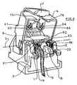
- Figure 1 shows the rear part of a modular jack ⁇ monopair prise.
- This socket has two metal insulation displacement contacts 1, 2 which, in this embodiment, each have two insulation displacement slots, as is the case for those described in the document EP-A-0.585.179 cited above.
- these two metal insulation displacement contacts 1, 2 each consist of two metallic thicknesses and are held in the rear plastic body 3 of the socket.
- This socket has, like that according to document EP-A-0.585.179, a rotary connection pusher 4 made of plastic which is produced in the form of a tilting cover or cap, the rotation of this pusher 4 taking place around an axis or pivot line 5 which is parallel to the row of insulation displacement contacts 1,2.
- FIG. 1 there are clearly distinguished the two pairs of push-buttons 61, 62 and 63, 64 which will drive out, when the tilting cap is closed, the wires to be connected in their self-stripping receiving slots, respectively from the metal contact 1 and metallic contact 2.
- FIG. 1 shows a sheathed telephone wire 6 which is placed in contact 1, at the entrance to its second insulation displacement slot and which is therefore ready to be connected by closing the rotary connection push-button 4.
- the tilting cap, or rotary pusher 4 comprises an elastic pawl 7 for locking by snap-fastening at the end of the race, this pawl 7 cooperating with a fixed stop 8 for snap locking at the end of the stroke.
- This stop 8 is formed by a plastic spout which is part of the body 3 and which is obtained by molding with the latter.
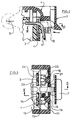
- These retaining grooves, 11, 12, 21, 22, the section of which is also clearly visible in FIG. 3, are each placed in the immediate vicinity of one of the insulation displacement slots, respectively (FIG. 3) 13, 14, 23, 24 More precisely, moreover, they are each placed under its respective insulation displacement slot and a little in front (in the right-left direction in the figures) of this slot.
- the section of these retaining grooves is adapted (see FIG. 3) to the diameter of the wire 6, so as to slightly wedge the latter when it is introduced (FIGS. 1 and 3) into one of these grooves.
- This implementation is also advantageously facilitated by the fact that there is provided, at the rear of each insulation displacement slot, a stop or semi-circular semi-cavity for receiving and holding the free end of the wire 6 , respectively 91 to 94 for the slots 12, 14, 23, 24.
- this plastic part 9 having arches 91 to 94 in a semicircle, in the manner of a bridge.
- this plastic part could include complete cavities, or wells, of circular section and adapted to that of the wires 6 so as to receive the free end of each of them.
- the closure cap 4 has on its internal face (see FIGS. 1 and 3) small internal ribs 15, 16 which are arranged (FIG. 3) to close the pairs of grooves 11, 12 and 21, 22 respectively when the cap 4 is closed and locked as shown in FIG. 2.
- These ribs 15, 16 therefore play the role of a closing cover for each of these two pairs of grooves.
- a single rib for example, comes to close two adjacent grooves at once, 11 and 12.
- the metal insulation displacement contacts can each be made of a single metal thickness instead of two. It applies equally well in particular to modular-jack sockets for multiple lines as well as rotary pushers for multiple connections.
- the axis 5 could be replaced by an equivalent hinge device: for example, the cap 4 could be connected to the body 3 by a flexible tab made of plastic.
- the invention applies to the field of connectors in general, and not only to that of telephone or computer connections.
Abstract
Description
La présente invention se rapporte à un dispositif de connexion par utilisation de contacts métalliques à au moins une fente autodénudante.The present invention relates to a device for connection by use of metal contacts to at least one insulation displacement slot.
La technique de connexion, en particulier de lignes téléphoniques, par la technique des contacts métalliques à fente autodénudante est maintenant largement répandue dans cette technique très spécialisée.The technique of connection, in particular of telephone lines, by the technique of metal contacts with insulation displacement gap is now widely used in this very specialized technique.
A ce titre, le document EP-A-0.585.179 décrit une prise femelle de type 〈〈 modular jack 〉〉 et à connectique intégrée, pour laquelle les contacts modular jack sont repris, à l'arrière de la prise, sur des contacts à fentes autodénudantes. La connexion d'un fil téléphonique à l'arrière de la prise s'effectue, sans outil spécifique, par fermeture d'un chapeau rotatif qui est associé à ces contacts autodénudants et qui sert de poussoir de connexion.As such, the document EP-A-0.585.179 describes a female socket of type 〈〈 modular jack 〉〉 and with integrated connection, for which the modular jack contacts are taken up, at the rear of the socket, on contacts with insulation displacement slots. The connection of a telephone wire to the rear of the socket is made, without any specific tool, by closing a rotary cap which is associated with these insulation displacement contacts and which serves as a connection pushbutton.
Ces dispositifs connus présentent les inconvénients suivants :
- L'opération de connexion d'un fil est peu commode à réaliser, du fait que l'opérateur doit tenir le fil d'une main pour bien le positionner à l'entrée de la fente autodénudante pendant qu'il utilise l'autre main pour fermer le chapeau de connexion rotatif.
- une fois la connexion réalisée, tous les efforts extérieurs qui s'exercent sur le fil, par exemple lors de l'insertion de la prise dans un réceptacle encastré ou non, sont appliqués sur le contact autodénudant et il y a alors un risque non négligeable de déconnexion accidentelle ou de rupture de ce fil.
caractérisé :
- en ce qu'il comporte en outre, près de chaque fente autodénudante, une petite rainure de maintien du fil dans laquelle ce dernier peut être introduit afin de le maintenir en place dans ladite fente pour l'actionnement dudit chapeau mobile,
- et en ce que ledit chapeau comporte en outre un ou des organes de fermeture de chacune de ces petites rainures de maintien qui sont mis en place lorsque ce chapeau est en position de fermeture totale et qui, en coopération avec la nervure associée, maintiennent fermement le fil et reprennent pratiquement alors les forces extérieures de traction ou de compression qui peuvent par la suite s'exercer sur ce fil.
- The operation of connecting a wire is awkward to carry out, because the operator must hold the wire with one hand to properly position it at the entrance to the insulation displacement slot while using the other hand. to close the rotary connection cap.
- once the connection has been made, all the external forces exerted on the wire, for example when inserting the plug into a receptacle, whether embedded or not, are applied to the insulation displacement contact and there is then a considerable risk accidental disconnection or breakage of this wire.
characterized:
- in that it further comprises, near each insulation displacement slot, a small groove for holding the wire into which the latter can be introduced in order to hold it in place in said slot for actuation of said movable cap,
- and in that said cap further comprises one or more closing members of each of these small retaining grooves which are put in place when this cap is in the fully closed position and which, in cooperation with the associated rib, firmly hold the wire and practically resume the external forces of traction or compression which can subsequently be exerted on this wire.
Avantageusement, chaque organe de fermeture est constitué par au moins un petit couvercle qui vient, en position de fermeture du chapeau, s'adapter sur au moins une rainure pour fermer celle-ci en enserrant étroitement le fil. Selon une forme de réalisation, ce couvercle est prévu pour venir refermer simultanément deux rainures adjacentes.Advantageously, each closure member is constituted by at least one small cover which, in the closed position of the cap, fits over at least one groove to close the latter by tightly enclosing the wire. According to one embodiment, this cover is designed to close two adjacent grooves simultaneously.
Préférentiellement par ailleurs, ledit chapeau de fermeture est un chapeau rotatif qui se referme en tournant autour d'une ligne de basculement.Preferably, moreover, said closure cap is a rotary cap which closes by turning around a tilting line.
Préférentiellement aussi, le chapeau de fermeture présente au moins un organe de verrouillage en sa position de fermeture, de sorte que cet organe de verrouillage vient maintenir fermement chaque couvercle sur la rainure de maintien qu'il vient refermer.Also preferably, the closure cap has at least one locking member in its closed position, so that this locking member comes to firmly hold each cover on the retaining groove that it comes to close.
L'invention sera bien comprise et ses avantages et autres caractéristiques ressortiront mieux, lors de la description suivante d'un exemple non limitatif de réalisation, en référence au dessin schématique annexé dans lequel :
- Figure 1 est une vue en perspective de la partie arrière d'une prise 〈〈 modular jack 〉〉 monopaire, cette partie arrière constituant un dispositif de connexion, par contacts autodénudants, d'une ligne téléphonique ou informatique, un fil étant ici mis en place pour être connecté, et le poussoir de connexion étant en position ouverte.
- Figure 2 est une vue en coupe longitudinale partielle, selon II-II de Figure 3, qui montre ce même dispositif avec le poussoir basculant fermé et le fil connecté.
- Figure 3 est une vue en coupe horizontale selon III-III de Figure 2.
- Figure 1 is a perspective view of the rear part of a modular jack 〈〈 modular jack 〉〉, this rear part constituting a connection device, by insulation displacement contacts, of a telephone or computer line, a wire being put in place here to be connected, and the connection pusher being in the open position.
- Figure 2 is a partial longitudinal sectional view, along line II-II of Figure 3, which shows this same device with the tilting pusher closed and the wire connected.
- Figure 3 is a horizontal sectional view along III-III of Figure 2.
La figure 1 montre la partie arrière d'une prise 〈〈 modular jack 〉〉 monopaire. Cette prise comporte deux contacts métalliques autodénudants 1, 2 qui, dans cet exemple de réalisation, comportent chacun deux fentes autodénudantes, comme c'est le cas pour ceux décrits dans le document EP-A-0.585.179 précité.Figure 1 shows the rear part of a modular jack 〉〉 monopair prise. This socket has two metal
Comme on le voit mieux sur la figure 2, ces deux contacts métalliques autodénudants 1, 2 sont chacun constitués de deux épaisseurs métalliques et sont maintenus dans le corps plastique arrière 3 de la prise.As best seen in Figure 2, these two metal
Cette prise possède, à l'instar de celle selon le document EP-A-0.585.179, un poussoir de connexion rotatif 4 en matière plastique qui est réalisé sous la forme d'un couvercle ou chapeau basculant, la rotation de ce poussoir 4 s'effectuant autour d'un axe ou ligne de pivotement 5 qui est parallèle à la rangée de contacts autodénudants 1,2.This socket has, like that according to document EP-A-0.585.179, a
Sur la figure 1, on distingue nettement les deux couples de lamespoussoir 61, 62 et 63, 64 qui vont venir chasser, lorsque l'on va refermer le chapeau basculant, les fils à connecter dans leurs fentes autodénudantes réceptrices, respectivement du contact métallique 1 et du contact métallique 2.In FIG. 1, there are clearly distinguished the two pairs of push-
A titre illustratif la figure 1 montre un fil téléphonique gainé 6 qui est mis en place dans le contact 1, à l'entrée de sa deuxième fente autodénudante et qui est donc prêt à être connecté par fermeture du poussoir de connexion rotatif 4.By way of illustration, FIG. 1 shows a sheathed telephone wire 6 which is placed in
Le chapeau basculant, ou poussoir rotatif 4 comporte un cliquet élastique 7 de verrouillage par encliquetage en fin de course, ce cliquet 7 coopérant avec une butée fixe 8 de verrouillage par encliquetage en fin de course. Cette butée 8 est formée par un bec en matière plastique qui fait partie du corps 3 et qui est obtenu de moulage avec ce dernier.The tilting cap, or
Conformément à l'invention, il est prévu, de moulage ici avec le corps plastique 3, des petites rainures de maintien 11, 12, 21, 22 des fils respectifs 6 à connecter.According to the invention, provision is made here for molding here with the
Ces rainures de maintien, 11, 12, 21, 22, dont la section est également bien visible sur la figure 3, sont chacune placées à proximité immédiate d'une des fentes autodénudantes, respectivement (figure 3) 13, 14, 23, 24. Plus précisément d'ailleurs, elles sont placées chacune sous sa fente autodénudante respective et un peu en avant (dans le sens droite-gauche sur les figures) de cette fente.These retaining grooves, 11, 12, 21, 22, the section of which is also clearly visible in FIG. 3, are each placed in the immediate vicinity of one of the insulation displacement slots, respectively (FIG. 3) 13, 14, 23, 24 More precisely, moreover, they are each placed under its respective insulation displacement slot and a little in front (in the right-left direction in the figures) of this slot.
la section de ces rainures de maintien est adaptée (voir figure 3) au diamètre du fil 6, de manière à légèrement coincer celui-ci lorsqu'il est introduit (figures 1 et 3) dans une de ces rainures.the section of these retaining grooves is adapted (see FIG. 3) to the diameter of the wire 6, so as to slightly wedge the latter when it is introduced (FIGS. 1 and 3) into one of these grooves.
Ces rainures permettent, en premier lieu et comme schématisé sur la figure 1, de maintenir le fil 6 en place dans sa fente autodénudante respective 14 avant que l'on actionne le poussoir rotatif 4 pour chasser ce fil dans cette fente et réaliser alors la connexion autodénudante.These grooves allow, first and as shown schematically in Figure 1, to maintain the wire 6 in place in its respective
Cette mise en place est d'ailleurs avantageusement facilitée par le fait qu'il est prévu, à l'arrière de chaque fente autodénudante, une butée ou demi-cavité semi-circulaire de réception et de maintien de l'extrémité libre du fil 6, respectivement 91 à 94 pour les fentes 12, 14, 23, 24.This implementation is also advantageously facilitated by the fact that there is provided, at the rear of each insulation displacement slot, a stop or semi-circular semi-cavity for receiving and holding the free end of the wire 6 , respectively 91 to 94 for the
Ces demi-cavités de maintien sont formées dans une pièce plastique transversale 9 possédant des arches 91 à 94 en demi-cercle, à la manière d'un pont. En variante, cette pièce plastique pourrait comporter des cavités complètes, ou puits, de section circulaire et adaptée à celle des fils 6 de façon à recevoir l'extrémité libre de chacun d'eux.These holding half-cavities are formed in a transverse
Une fois le fil 6 mis en place, selon Figure 1, dans sa demi-cavité réceptrice 92, dans le 〈〈 Vé 〉〉 d'entrée de sa fente autodénudante respective 14 et dans sa rainure de maintien 12, ce fil tient suffisamment bien en place pour qu'on puisse le lâcher, ce qui libère une main pour pouvoir alors aisément actionner le poussoir rotatif 4.Once the wire 6 is in place, according to FIG. 1, in its receiving half-
En outre, le chapeau de fermeture 4 comporte sur sa face interne (voir figures 1 et 3) des petites nervures intérieures 15, 16 qui sont agencées (figure 3) pour venir respectivement fermer les couples de rainures 11, 12 et 21, 22 lorsque le chapeau 4 est fermé et verrouillé comme montré en figure 2. Ces nervures 15, 16 jouent donc le rôle d'un couvercle de fermeture pour chacun de ces deux couples de rainures. Ici, une seule nervure, 15 par exemple, vient fermer deux rainures adjacentes à la fois, 11 et 12. En variante, on pourrait prévoir une nervure respective pour fermer chaque rainure séparément.In addition, the
Lorsque finalement le chapeau basculant est fermé et verrouillé, selon Figures 2 et 3, le fil 6 est descendu, poussé par sa lame-poussoir respective 62, dans sa fente autodénudante 14. Il est donc dénudé et connecté. En outre, il est maintenu fermement dans sa rainure de maintien 12 par le fait que le couvercle de fermeture 15 de cette rainure est solidement verrouillé par l'effet du dispositif de verrouillage 7, 8. Toutes les sollicitations extérieures qui peuvent s'exercer, en particulier lors de la mise en place de la prise dans sa cavité d'encastrement, sur le fil 6 sont alors reprises par la rainure de maintien 12 et ne sont pratiquement donc pas transmises à la fente autodénudante 14.When finally the tilting cap is closed and locked, according to Figures 2 and 3, the wire 6 is lowered, pushed by its respective push-
Comme il va de soi, l'invention n'est pas limitée à l'exemple de réalisation qui vient d'être décrit. C'est ainsi par exemple que les contacts métalliques autodénudants peuvent être chacun constitués d'une seule épaisseur métallique au lieu de deux. Elle s'applique aussi bien en particulier aux prises modular-jack pour lignes multiples ainsi qu'aux poussoirs rotatifs de connexion multiples. L'axe 5 pourrait être remplacé par un dispositif de charnière équivalent : par exemple, le chapeau 4 pourrait être relié au corps 3 par une languette souple ne matière plastique. L'invention s'applique au domaine de la connectique en général, et non pas seulement à celui de la connectique téléphonique ou informatique.It goes without saying that the invention is not limited to the embodiment which has just been described. For example, the metal insulation displacement contacts can each be made of a single metal thickness instead of two. It applies equally well in particular to modular-jack sockets for multiple lines as well as rotary pushers for multiple connections. The axis 5 could be replaced by an equivalent hinge device: for example, the
Claims (6)
caractérisé :
characterized:
Priority Applications (5)
| Application Number | Priority Date | Filing Date | Title |
|---|---|---|---|
| AT96420150T ATE217456T1 (en) | 1996-05-02 | 1996-05-02 | CONNECTION ARRANGEMENT WITH CUTTING CONTACTS |
| PT96420150T PT805518E (en) | 1996-05-02 | 1996-05-02 | CONNECTION DEVICE WITH SELF-DESCARNANT CONTACTS |
| EP96420150A EP0805518B1 (en) | 1996-05-02 | 1996-05-02 | Connecting device with insulation displacing contacts |
| ES96420150T ES2175057T3 (en) | 1996-05-02 | 1996-05-02 | CONNECTION DEVICE WITH SELF-NUDING CONTACTS. |
| DE69621117T DE69621117T2 (en) | 1996-05-02 | 1996-05-02 | Connection arrangement with cutting contacts |
Applications Claiming Priority (1)
| Application Number | Priority Date | Filing Date | Title |
|---|---|---|---|
| EP96420150A EP0805518B1 (en) | 1996-05-02 | 1996-05-02 | Connecting device with insulation displacing contacts |
Publications (2)
| Publication Number | Publication Date |
|---|---|
| EP0805518A1 true EP0805518A1 (en) | 1997-11-05 |
| EP0805518B1 EP0805518B1 (en) | 2002-05-08 |
Family
ID=8225385
Family Applications (1)
| Application Number | Title | Priority Date | Filing Date |
|---|---|---|---|
| EP96420150A Expired - Lifetime EP0805518B1 (en) | 1996-05-02 | 1996-05-02 | Connecting device with insulation displacing contacts |
Country Status (5)
| Country | Link |
|---|---|
| EP (1) | EP0805518B1 (en) |
| AT (1) | ATE217456T1 (en) |
| DE (1) | DE69621117T2 (en) |
| ES (1) | ES2175057T3 (en) |
| PT (1) | PT805518E (en) |
Cited By (2)
| Publication number | Priority date | Publication date | Assignee | Title |
|---|---|---|---|---|
| US6224419B1 (en) | 1999-06-30 | 2001-05-01 | Stephen Craig Tucker | Sealant-filled electrical connector and method for forming the same |
| CN115241824A (en) * | 2022-07-31 | 2022-10-25 | 贵州电网有限责任公司 | Terminal box of metering box |
Families Citing this family (1)
| Publication number | Priority date | Publication date | Assignee | Title |
|---|---|---|---|---|
| DE10238852B3 (en) * | 2002-08-24 | 2004-01-29 | K.A. Schmersal Gmbh & Co | switchgear |
Citations (3)
| Publication number | Priority date | Publication date | Assignee | Title |
|---|---|---|---|---|
| GB2103432A (en) * | 1981-07-13 | 1983-02-16 | Communications Tech Corp | Cable connector |
| GB2168860A (en) * | 1984-12-20 | 1986-06-25 | Starpoint Electrics Ltd | Lampholder |
| EP0671780A1 (en) * | 1994-03-10 | 1995-09-13 | Reichle + De-Massari AG Elektro-Ingenieure | Multiple contact and terminal block for communications equipment |
-
1996
- 1996-05-02 EP EP96420150A patent/EP0805518B1/en not_active Expired - Lifetime
- 1996-05-02 ES ES96420150T patent/ES2175057T3/en not_active Expired - Lifetime
- 1996-05-02 PT PT96420150T patent/PT805518E/en unknown
- 1996-05-02 DE DE69621117T patent/DE69621117T2/en not_active Expired - Fee Related
- 1996-05-02 AT AT96420150T patent/ATE217456T1/en not_active IP Right Cessation
Patent Citations (3)
| Publication number | Priority date | Publication date | Assignee | Title |
|---|---|---|---|---|
| GB2103432A (en) * | 1981-07-13 | 1983-02-16 | Communications Tech Corp | Cable connector |
| GB2168860A (en) * | 1984-12-20 | 1986-06-25 | Starpoint Electrics Ltd | Lampholder |
| EP0671780A1 (en) * | 1994-03-10 | 1995-09-13 | Reichle + De-Massari AG Elektro-Ingenieure | Multiple contact and terminal block for communications equipment |
Cited By (3)
| Publication number | Priority date | Publication date | Assignee | Title |
|---|---|---|---|---|
| US6224419B1 (en) | 1999-06-30 | 2001-05-01 | Stephen Craig Tucker | Sealant-filled electrical connector and method for forming the same |
| CN115241824A (en) * | 2022-07-31 | 2022-10-25 | 贵州电网有限责任公司 | Terminal box of metering box |
| CN115241824B (en) * | 2022-07-31 | 2023-11-17 | 贵州电网有限责任公司 | Junction box of metering box |
Also Published As
| Publication number | Publication date |
|---|---|
| DE69621117D1 (en) | 2002-06-13 |
| PT805518E (en) | 2002-08-30 |
| ES2175057T3 (en) | 2002-11-16 |
| DE69621117T2 (en) | 2002-10-31 |
| EP0805518B1 (en) | 2002-05-08 |
| ATE217456T1 (en) | 2002-05-15 |
Similar Documents
| Publication | Publication Date | Title |
|---|---|---|
| EP0863583B1 (en) | Modular jack type wall female socket | |
| EP1496572B1 (en) | Connecting device for coaxial cable | |
| FR2488060A1 (en) | POWER CABIN CONNECTOR WITH RESTRAINT SPRING | |
| EP0837526B1 (en) | Automatic connnection terminal and an electrical device fitted with such a terminal | |
| FR2465323A1 (en) | CONNECTOR FOR CONNECTION TO THE TAKE-OUT TERMINALS OF AN ELECTRIC BATTERY OR ACCUMULATOR | |
| EP0805518B1 (en) | Connecting device with insulation displacing contacts | |
| EP0805517A1 (en) | Connection process and device with insulation piercing contact | |
| WO2008132307A2 (en) | Ergonomic electrical connection system with a high level of security | |
| EP0419301B1 (en) | Self-stripping connector with elements which cross themselves | |
| EP0913881A1 (en) | Line connection device with insulation displacement contacts | |
| EP0697749B1 (en) | Quick cutting terminal contact | |
| WO2015113972A1 (en) | Connector with lever for connection assistance | |
| EP2045881B1 (en) | Plug-in power socket including an opening socket body and a switching mobile terminal block | |
| EP1999823B1 (en) | Low voltage connector | |
| FR2750803A1 (en) | Electrical connector for switching module | |
| FR2691846A1 (en) | Auto-stripping contact electric current holder - connects power cables using insulated body with electric joining plug having electric contact pins and female receptor to receive connector | |
| FR2563383A1 (en) | Power-outlet plug having a traction member | |
| EP1496575B1 (en) | Contact | |
| FR2839819A1 (en) | Clamp box for hollow closures, used to embed switch or power outlet in this closure in buildings, has pivoting units allowing rotation of clamp | |
| EP0033675A1 (en) | Electric device with a safety fuse carrier | |
| FR2751482A1 (en) | DEVICE FOR PERFORMING A SPLICE | |
| FR2610561A1 (en) | Ratchet handle intended for tightening a screw, particularly in an electrical cable connector | |
| FR2568418A1 (en) | MULTIPOLAR ELECTRICAL CONNECTOR. | |
| FR2600217A1 (en) | Coaxial-cable tap-off connector and corresponding substitution closure device | |
| WO1993012563A1 (en) | Device for pulling out a plug |
Legal Events
| Date | Code | Title | Description |
|---|---|---|---|
| PUAI | Public reference made under article 153(3) epc to a published international application that has entered the european phase |
Free format text: ORIGINAL CODE: 0009012 |
|
| AK | Designated contracting states |
Kind code of ref document: A1 Designated state(s): AT BE CH DE DK ES FI FR GB GR IE IT LI LU MC NL PT SE |
|
| 17P | Request for examination filed |
Effective date: 19980328 |
|
| GRAG | Despatch of communication of intention to grant |
Free format text: ORIGINAL CODE: EPIDOS AGRA |
|
| GRAG | Despatch of communication of intention to grant |
Free format text: ORIGINAL CODE: EPIDOS AGRA |
|
| REG | Reference to a national code |
Ref country code: GB Ref legal event code: IF02 |
|
| GRAG | Despatch of communication of intention to grant |
Free format text: ORIGINAL CODE: EPIDOS AGRA |
|
| GRAH | Despatch of communication of intention to grant a patent |
Free format text: ORIGINAL CODE: EPIDOS IGRA |
|
| 17Q | First examination report despatched |
Effective date: 20011122 |
|
| RTI1 | Title (correction) |
Free format text: CONNECTING DEVICE WITH INSULATION DISPLACING CONTACTS |
|
| GRAH | Despatch of communication of intention to grant a patent |
Free format text: ORIGINAL CODE: EPIDOS IGRA |
|
| GRAA | (expected) grant |
Free format text: ORIGINAL CODE: 0009210 |
|
| AK | Designated contracting states |
Kind code of ref document: B1 Designated state(s): AT BE CH DE DK ES FI FR GB GR IE IT LI LU MC NL PT SE |
|
| PG25 | Lapsed in a contracting state [announced via postgrant information from national office to epo] |
Ref country code: NL Free format text: LAPSE BECAUSE OF FAILURE TO SUBMIT A TRANSLATION OF THE DESCRIPTION OR TO PAY THE FEE WITHIN THE PRESCRIBED TIME-LIMIT Effective date: 20020508 Ref country code: IE Free format text: LAPSE BECAUSE OF FAILURE TO SUBMIT A TRANSLATION OF THE DESCRIPTION OR TO PAY THE FEE WITHIN THE PRESCRIBED TIME-LIMIT Effective date: 20020508 Ref country code: GR Free format text: LAPSE BECAUSE OF FAILURE TO SUBMIT A TRANSLATION OF THE DESCRIPTION OR TO PAY THE FEE WITHIN THE PRESCRIBED TIME-LIMIT Effective date: 20020508 Ref country code: FI Free format text: LAPSE BECAUSE OF FAILURE TO SUBMIT A TRANSLATION OF THE DESCRIPTION OR TO PAY THE FEE WITHIN THE PRESCRIBED TIME-LIMIT Effective date: 20020508 Ref country code: AT Free format text: LAPSE BECAUSE OF FAILURE TO SUBMIT A TRANSLATION OF THE DESCRIPTION OR TO PAY THE FEE WITHIN THE PRESCRIBED TIME-LIMIT Effective date: 20020508 |
|
| REF | Corresponds to: |
Ref document number: 217456 Country of ref document: AT Date of ref document: 20020515 Kind code of ref document: T |
|
| REG | Reference to a national code |
Ref country code: CH Ref legal event code: EP |
|
| REG | Reference to a national code |
Ref country code: IE Ref legal event code: FG4D Free format text: FRENCH |
|
| REF | Corresponds to: |
Ref document number: 69621117 Country of ref document: DE Date of ref document: 20020613 |
|
| PG25 | Lapsed in a contracting state [announced via postgrant information from national office to epo] |
Ref country code: SE Free format text: LAPSE BECAUSE OF FAILURE TO SUBMIT A TRANSLATION OF THE DESCRIPTION OR TO PAY THE FEE WITHIN THE PRESCRIBED TIME-LIMIT Effective date: 20020808 Ref country code: DK Free format text: LAPSE BECAUSE OF FAILURE TO SUBMIT A TRANSLATION OF THE DESCRIPTION OR TO PAY THE FEE WITHIN THE PRESCRIBED TIME-LIMIT Effective date: 20020808 |
|
| GBT | Gb: translation of ep patent filed (gb section 77(6)(a)/1977) |
Effective date: 20020720 |
|
| REG | Reference to a national code |
Ref country code: PT Ref legal event code: SC4A Free format text: AVAILABILITY OF NATIONAL TRANSLATION Effective date: 20020528 |
|
| NLV1 | Nl: lapsed or annulled due to failure to fulfill the requirements of art. 29p and 29m of the patents act | ||
| REG | Reference to a national code |
Ref country code: ES Ref legal event code: FG2A Ref document number: 2175057 Country of ref document: ES Kind code of ref document: T3 |
|
| REG | Reference to a national code |
Ref country code: IE Ref legal event code: FD4D Ref document number: 0805518E Country of ref document: IE |
|
| PLBE | No opposition filed within time limit |
Free format text: ORIGINAL CODE: 0009261 |
|
| STAA | Information on the status of an ep patent application or granted ep patent |
Free format text: STATUS: NO OPPOSITION FILED WITHIN TIME LIMIT |
|
| PGFP | Annual fee paid to national office [announced via postgrant information from national office to epo] |
Ref country code: PT Payment date: 20030424 Year of fee payment: 8 |
|
| 26N | No opposition filed |
Effective date: 20030211 |
|
| PG25 | Lapsed in a contracting state [announced via postgrant information from national office to epo] |
Ref country code: LU Free format text: LAPSE BECAUSE OF NON-PAYMENT OF DUE FEES Effective date: 20030502 |
|
| PGFP | Annual fee paid to national office [announced via postgrant information from national office to epo] |
Ref country code: CH Payment date: 20030522 Year of fee payment: 8 |
|
| PG25 | Lapsed in a contracting state [announced via postgrant information from national office to epo] |
Ref country code: MC Free format text: LAPSE BECAUSE OF NON-PAYMENT OF DUE FEES Effective date: 20030531 Ref country code: BE Free format text: LAPSE BECAUSE OF NON-PAYMENT OF DUE FEES Effective date: 20030531 |
|
| BERE | Be: lapsed |
Owner name: S.A. *POUYET Effective date: 20030531 |
|
| PG25 | Lapsed in a contracting state [announced via postgrant information from national office to epo] |
Ref country code: LI Free format text: LAPSE BECAUSE OF NON-PAYMENT OF DUE FEES Effective date: 20040531 Ref country code: CH Free format text: LAPSE BECAUSE OF NON-PAYMENT OF DUE FEES Effective date: 20040531 |
|
| PG25 | Lapsed in a contracting state [announced via postgrant information from national office to epo] |
Ref country code: PT Free format text: LAPSE BECAUSE OF NON-PAYMENT OF DUE FEES Effective date: 20041102 |
|
| REG | Reference to a national code |
Ref country code: CH Ref legal event code: PL |
|
| REG | Reference to a national code |
Ref country code: PT Ref legal event code: MM4A Effective date: 20041102 |
|
| PGFP | Annual fee paid to national office [announced via postgrant information from national office to epo] |
Ref country code: GB Payment date: 20060525 Year of fee payment: 11 |
|
| PGFP | Annual fee paid to national office [announced via postgrant information from national office to epo] |
Ref country code: IT Payment date: 20060531 Year of fee payment: 11 |
|
| PGFP | Annual fee paid to national office [announced via postgrant information from national office to epo] |
Ref country code: DE Payment date: 20060630 Year of fee payment: 11 |
|
| GBPC | Gb: european patent ceased through non-payment of renewal fee |
Effective date: 20070502 |
|
| PG25 | Lapsed in a contracting state [announced via postgrant information from national office to epo] |
Ref country code: DE Free format text: LAPSE BECAUSE OF NON-PAYMENT OF DUE FEES Effective date: 20071201 |
|
| PG25 | Lapsed in a contracting state [announced via postgrant information from national office to epo] |
Ref country code: GB Free format text: LAPSE BECAUSE OF NON-PAYMENT OF DUE FEES Effective date: 20070502 |
|
| PGFP | Annual fee paid to national office [announced via postgrant information from national office to epo] |
Ref country code: ES Payment date: 20090526 Year of fee payment: 14 |
|
| PGFP | Annual fee paid to national office [announced via postgrant information from national office to epo] |
Ref country code: FR Payment date: 20090518 Year of fee payment: 14 |
|
| PG25 | Lapsed in a contracting state [announced via postgrant information from national office to epo] |
Ref country code: IT Free format text: LAPSE BECAUSE OF NON-PAYMENT OF DUE FEES Effective date: 20070502 |
|
| REG | Reference to a national code |
Ref country code: FR Ref legal event code: ST Effective date: 20110131 |
|
| PG25 | Lapsed in a contracting state [announced via postgrant information from national office to epo] |
Ref country code: FR Free format text: LAPSE BECAUSE OF NON-PAYMENT OF DUE FEES Effective date: 20100531 |
|
| REG | Reference to a national code |
Ref country code: ES Ref legal event code: FD2A Effective date: 20110715 |
|
| PG25 | Lapsed in a contracting state [announced via postgrant information from national office to epo] |
Ref country code: ES Free format text: LAPSE BECAUSE OF NON-PAYMENT OF DUE FEES Effective date: 20110705 |
|
| PG25 | Lapsed in a contracting state [announced via postgrant information from national office to epo] |
Ref country code: ES Free format text: LAPSE BECAUSE OF NON-PAYMENT OF DUE FEES Effective date: 20100503 |