EP0805468A2 - Ensemble interrupteur avec au moins deux interrupteurs rotatifs - Google Patents
Ensemble interrupteur avec au moins deux interrupteurs rotatifs Download PDFInfo
- Publication number
- EP0805468A2 EP0805468A2 EP97107026A EP97107026A EP0805468A2 EP 0805468 A2 EP0805468 A2 EP 0805468A2 EP 97107026 A EP97107026 A EP 97107026A EP 97107026 A EP97107026 A EP 97107026A EP 0805468 A2 EP0805468 A2 EP 0805468A2
- Authority
- EP
- European Patent Office
- Prior art keywords
- rotary
- switch
- contact
- arrangement according
- contacts
- Prior art date
- Legal status (The legal status is an assumption and is not a legal conclusion. Google has not performed a legal analysis and makes no representation as to the accuracy of the status listed.)
- Withdrawn
Links
Images

Classifications
-
- H—ELECTRICITY
- H01—ELECTRIC ELEMENTS
- H01H—ELECTRIC SWITCHES; RELAYS; SELECTORS; EMERGENCY PROTECTIVE DEVICES
- H01H19/00—Switches operated by an operating part which is rotatable about a longitudinal axis thereof and which is acted upon directly by a solid body external to the switch, e.g. by a hand
- H01H19/02—Details
- H01H19/10—Movable parts; Contacts mounted thereon
- H01H19/14—Operating parts, e.g. turn knob
-
- H—ELECTRICITY
- H01—ELECTRIC ELEMENTS
- H01H—ELECTRIC SWITCHES; RELAYS; SELECTORS; EMERGENCY PROTECTIVE DEVICES
- H01H19/00—Switches operated by an operating part which is rotatable about a longitudinal axis thereof and which is acted upon directly by a solid body external to the switch, e.g. by a hand
- H01H19/02—Details
- H01H19/10—Movable parts; Contacts mounted thereon
- H01H19/11—Movable parts; Contacts mounted thereon with indexing means
-
- H—ELECTRICITY
- H01—ELECTRIC ELEMENTS
- H01H—ELECTRIC SWITCHES; RELAYS; SELECTORS; EMERGENCY PROTECTIVE DEVICES
- H01H19/00—Switches operated by an operating part which is rotatable about a longitudinal axis thereof and which is acted upon directly by a solid body external to the switch, e.g. by a hand
- H01H19/54—Switches operated by an operating part which is rotatable about a longitudinal axis thereof and which is acted upon directly by a solid body external to the switch, e.g. by a hand the operating part having at least five or an unspecified number of operative positions
- H01H19/56—Angularly-movable actuating part carrying contacts, e.g. drum switch
- H01H19/58—Angularly-movable actuating part carrying contacts, e.g. drum switch having only axial contact pressure, e.g. disc switch, wafer switch
- H01H19/585—Angularly-movable actuating part carrying contacts, e.g. drum switch having only axial contact pressure, e.g. disc switch, wafer switch provided with printed circuit contacts
-
- H—ELECTRICITY
- H01—ELECTRIC ELEMENTS
- H01H—ELECTRIC SWITCHES; RELAYS; SELECTORS; EMERGENCY PROTECTIVE DEVICES
- H01H19/00—Switches operated by an operating part which is rotatable about a longitudinal axis thereof and which is acted upon directly by a solid body external to the switch, e.g. by a hand
- H01H19/64—Encased switches adapted for ganged operation when assembled in a line with identical switches, e.g. stacked switches
-
- H—ELECTRICITY
- H01—ELECTRIC ELEMENTS
- H01H—ELECTRIC SWITCHES; RELAYS; SELECTORS; EMERGENCY PROTECTIVE DEVICES
- H01H19/00—Switches operated by an operating part which is rotatable about a longitudinal axis thereof and which is acted upon directly by a solid body external to the switch, e.g. by a hand
- H01H19/02—Details
- H01H19/10—Movable parts; Contacts mounted thereon
- H01H19/14—Operating parts, e.g. turn knob
- H01H2019/143—Operating parts, e.g. turn knob having at least two concentric turn knobs
Definitions
- the invention relates to a switch arrangement with at least two rotary switches according to claim 1.
- Switches of the aforementioned type are in particular provided to select different operating modes or different temperatures of an oven control and to generate commands in the form of the respectively set operating modes, coded electrical signal patterns or pulses for an incremental temperature controller and to an electronic control - or control circuit, e.g. in the form of a microcontroller.
- the signal patterns for the electronic control or regulating circuit are each generated by means of a contact bridge grinder adjusted in accordance with the various switch positions, which grinds correspondingly coded contact tracks, preferably applied to contact disks.
- the inventive coaxial combination of two rotary switches that are otherwise to be arranged next to one another in the control panel to form a multiple rotary switch with rotary shafts that are concentric with one another makes it possible to reduce the size considerably, but in particular in the case of an arrangement of the control handles staggered concentrically in the direction of the rotary shaft, the rotary handles are nevertheless simple due to their different handling-side diameters and safe operation is guaranteed.
- the compactness of the entire switch arrangement can be further increased, in particular with regard to its axial compactness, by the fact that only a single contact disk is provided for at least two switches, the contact tracks or contacts assigned to each of the two rotary switches either on a different end face or concentrically with one another only one same end face of the single contact plate are arranged.
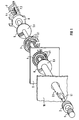
- FIG. 1 shows a multiple rotary switch with a first rotary switch 1 for setting different operating modes of an oven and a second rotary switch 2 concentrically arranged or operable for setting different temperatures of the oven.
- the controls of the two rotary switches 1 and 2 are arranged on the front of an operating panel 10.
- the adjusting movement of the first rotary switch 1 is transmitted via a first rotary shaft 1.1 in the form of an inner shaft and the adjusting movement of the second rotary switch 2 is transmitted via a concentric second rotary shaft 2.1 in the form of a hollow shaft surrounding the inner shaft.
- the rotary shafts 1.1 and 2.1 are inserted through a through opening in the front control panel 10.
- a contact bridge grinder 5 is in contact with the first rotary shaft 1.1 via a driving part 5.1
- a contact bridge grinder 6 is in rotation with the second rotary shaft 2.1 via a driving part 6.1.
- the contact tracks contain coded, circumferentially distributed, mutually contact-connected contact grinding surfaces, which can be connected via the contact bridge grinder 5 to a potential to which an inner contact grinding surface running over the entire circumference is connected.
- the contact bridge grinder 5 is in contact sliding contact with contact tracks 3.1 of a contact disk 3 and the contact bridge grinder 6 is in contact sliding contact with contacts 4.1 or contact tracks of a contact disk 4.
- the contact bridge grinder 6 Depending on the position of the contact bridge grinder 5 relative to the coded contact grinding surfaces of the contact tracks 3.1, there are specific signal patterns at the outputs of the contact tracks 3.1, which are preferably passed on to input pins of a control circuit, in particular in the form of a microcontroller, and there can be defined as certain set operating modes; Similarly, the contact bridge grinder 6 generates 4 pulses when grinding the contacts 4.1 or its inner contact grinding surfaces of the contact disk, which pulses are preferably used for switching edge-sensitive logic inputs of a microcontroller for an incremental temperature controller.
- the contact tracks 3.1 and contacts 4.1 of the contact disks 3 and 4 are an integral part of a circuit board 9 of the further control circuit, the contact disk 4 on the front of the circuit board 9 and the contact disk 3 shown in FIG. 1 for visualization with the rear turned toward the front is applied to the rear of the printed circuit board 9.
- a power switch 7 is also integrated with the switch arrangement shown in FIG. 1, by means of which the supply voltage can be applied to the entire control system before the actual operating modes are set; for this purpose, the first rotary shaft 1.1 of the rotary switch 1, which is designed as an inner shaft, is advantageously extended via the contact disk actuation 3; 5 and actuates spring contacts 7.2 when the first rotary switch 1 is rotated by means of switching cams 7.1 in the sense of switching the mains voltage on or off .
- the operating modes which can be set with the first rotary switch 1 can be fixed in their respective end position by means of a fixing part 8 which can be driven by the extended first rotary shaft 1.1.
- the rotary shaft 1.1 rotates a locking star 8.1 which can be positively plugged onto the switch holder and which fixes the setting position of the rotary switch 1 when a locking cam 8.2 is pressed radially by a spring 8.3 into notches in the locking star 8.1 a contact code corresponding to the operating mode between the contact bridge grinder 5 and the contact grinding surfaces of the contact tracks 3.1 Contact disk 3 is generated.
- the fixing part 8 - as can be seen in particular from FIG.
Landscapes
- Rotary Switch, Piano Key Switch, And Lever Switch (AREA)
Applications Claiming Priority (2)
| Application Number | Priority Date | Filing Date | Title |
|---|---|---|---|
| DE19617163 | 1996-04-29 | ||
| DE1996117163 DE19617163A1 (de) | 1996-04-29 | 1996-04-29 | Schalteranordnung mit zumindest zwei Drehschaltern |
Publications (2)
| Publication Number | Publication Date |
|---|---|
| EP0805468A2 true EP0805468A2 (fr) | 1997-11-05 |
| EP0805468A3 EP0805468A3 (fr) | 1998-09-09 |
Family
ID=7792817
Family Applications (1)
| Application Number | Title | Priority Date | Filing Date |
|---|---|---|---|
| EP97107026A Withdrawn EP0805468A3 (fr) | 1996-04-29 | 1997-04-28 | Ensemble interrupteur avec au moins deux interrupteurs rotatifs |
Country Status (2)
| Country | Link |
|---|---|
| EP (1) | EP0805468A3 (fr) |
| DE (1) | DE19617163A1 (fr) |
Cited By (2)
| Publication number | Priority date | Publication date | Assignee | Title |
|---|---|---|---|---|
| EP1081694A1 (fr) * | 1999-08-10 | 2001-03-07 | Nippon Columbia Co., Ltd. | Molette de contrôle et lecteur de disque optique en beneficiant |
| FR2973932A1 (fr) * | 2011-04-06 | 2012-10-12 | Peugeot Citroen Automobiles Sa | Dispositif de commutation a double element d'actionnement rotatif pour volant de vehicule et volant comprenant un tel dispositif de commutation |
Families Citing this family (4)
| Publication number | Priority date | Publication date | Assignee | Title |
|---|---|---|---|---|
| DE10202049A1 (de) * | 2002-01-18 | 2003-07-31 | Faude Consulting Gmbh R | Schaltanordnung für eine Haushaltsmaschine oder dergleichen |
| DE202005001066U1 (de) | 2005-01-21 | 2005-03-31 | Dreefs Gmbh Schaltgeraete | Energieregler für das Kochfeld von Elektroherden |
| DE102014102709A1 (de) * | 2014-02-28 | 2015-09-03 | Elrad International D.O.O. | Mehrfachschalter für ein Elektrogerät |
| DE102016218493A1 (de) | 2016-09-27 | 2018-03-29 | BSH Hausgeräte GmbH | Thermostatanordnung und Haushaltsgargerät |
Family Cites Families (8)
| Publication number | Priority date | Publication date | Assignee | Title |
|---|---|---|---|---|
| DE1219569B (de) * | 1961-12-19 | 1966-06-23 | Busch Jaeger Duerener Metall | Nockenwahlschalter mit Zeitwerk |
| FR2234645A1 (en) * | 1973-06-25 | 1975-01-17 | Diela | Rotary wafer switch with auxiliary contacts - spring loaded button operates auxiliary contact spindle in main spindle |
| GB1495880A (en) * | 1976-05-21 | 1977-12-21 | Standard Telephones Cables Ltd | Rotary electric switches |
| DE2848824C2 (de) * | 1978-11-10 | 1990-02-15 | Diehl Gmbh & Co, 8500 Nuernberg | Anordnung zur Leistungssteuerung |
| DE3240547A1 (de) * | 1982-11-03 | 1984-06-14 | Diehl Gmbh & Co | Schaltungsanordnung zum umschalten der leistungszufuhr zu elektrischen verbrauchern |
| DE3320769C2 (de) * | 1983-06-09 | 1987-02-05 | Standard Elektrik Lorenz Ag, 7000 Stuttgart | Impulsgenerator |
| JPH0414328U (fr) * | 1990-05-25 | 1992-02-05 | ||
| US5436413A (en) * | 1993-09-17 | 1995-07-25 | Hosiden Corporation | Multiple staged rotary switch |
-
1996
- 1996-04-29 DE DE1996117163 patent/DE19617163A1/de not_active Withdrawn
-
1997
- 1997-04-28 EP EP97107026A patent/EP0805468A3/fr not_active Withdrawn
Cited By (3)
| Publication number | Priority date | Publication date | Assignee | Title |
|---|---|---|---|---|
| EP1081694A1 (fr) * | 1999-08-10 | 2001-03-07 | Nippon Columbia Co., Ltd. | Molette de contrôle et lecteur de disque optique en beneficiant |
| US6771582B1 (en) | 1999-08-10 | 2004-08-03 | Denon, Ltd. | Control dial and optical disk apparatus having the control dial |
| FR2973932A1 (fr) * | 2011-04-06 | 2012-10-12 | Peugeot Citroen Automobiles Sa | Dispositif de commutation a double element d'actionnement rotatif pour volant de vehicule et volant comprenant un tel dispositif de commutation |
Also Published As
| Publication number | Publication date |
|---|---|
| EP0805468A3 (fr) | 1998-09-09 |
| DE19617163A1 (de) | 1997-11-06 |
Similar Documents
| Publication | Publication Date | Title |
|---|---|---|
| EP1349281B1 (fr) | Dispositif de commande pour un appareil électrique | |
| DE69629991T2 (de) | Rotationsdetektor in Kraftwagen | |
| EP1527469A1 (fr) | Commutateur rotatif | |
| EP1061429A1 (fr) | Bouton tournant escamotable | |
| EP0805467B1 (fr) | Interrupteur en particulier interrupteur rotatif | |
| EP0805468A2 (fr) | Ensemble interrupteur avec au moins deux interrupteurs rotatifs | |
| EP0805466B1 (fr) | Interrupteur, en particulier interrupteur commutable en modes d'opération différents, et procédé d'assemblage d'un tel interrupteurs | |
| EP1126941A1 (fr) | Dispositif de serrage d'une broche de machine | |
| EP2184746B1 (fr) | Appareil de réglage électromécanique doté d'un axe rotatif | |
| DE10111400B4 (de) | Stellantrieb für Heizungs-, Lüftungs- oder Klimaklappen in einem Kraftfahrzeug | |
| DE1665800B2 (de) | Drehschalterantrieb | |
| DE102022105293A1 (de) | Ventilsteuervorrichtung für einen Kühlmittelkreislauf eines Kraftfahrzeugs | |
| EP1272078A1 (fr) | Robot de cuisine | |
| EP1096524B1 (fr) | Dispositif de commutation rotatif avec bouton amovible | |
| DE2618114A1 (de) | Vorrichtung zur anzeige der stellung von drehbaren mechanischen elementen | |
| DE316886C (fr) | ||
| DE1538385C3 (de) | Programmschaltwerk | |
| DE2106224A1 (de) | Schalteinrichtung für Zeitschaltmeßgeräte | |
| DE2446861C3 (de) | Wisch- und Waschvorrichtung für Scheiben von Kraftfahrzeugen | |
| DE102022115079A1 (de) | Stellvorrichtung für ein Fahrzeug und Verfahren zum Betreiben einer Stellvorrichtung | |
| EP0743474A2 (fr) | Dispositif de déclenchement d'une action en fonction de la position angulaire d'un arbre | |
| EP0842822B1 (fr) | Bouton tournant. | |
| EP0304681A2 (fr) | Interrupteur horaire électrique à disque commutateur interchangeable | |
| DE19944463A1 (de) | Betätigungselement für ein verdrehbares Verstellelement | |
| EP4258307A1 (fr) | Appareil de technique d'installation domestique |
Legal Events
| Date | Code | Title | Description |
|---|---|---|---|
| PUAI | Public reference made under article 153(3) epc to a published international application that has entered the european phase |
Free format text: ORIGINAL CODE: 0009012 |
|
| AK | Designated contracting states |
Kind code of ref document: A2 Designated state(s): DE ES FR GB IT |
|
| PUAL | Search report despatched |
Free format text: ORIGINAL CODE: 0009013 |
|
| AK | Designated contracting states |
Kind code of ref document: A3 Designated state(s): DE ES FR GB IT |
|
| 17P | Request for examination filed |
Effective date: 19990309 |
|
| RAP1 | Party data changed (applicant data changed or rights of an application transferred) |
Owner name: BSH BOSCH UND SIEMENS HAUSGERAETE GMBH |
|
| 17Q | First examination report despatched |
Effective date: 20030707 |
|
| RAP1 | Party data changed (applicant data changed or rights of an application transferred) |
Owner name: BSH BOSCH UND SIEMENS HAUSGERAETE GMBH |
|
| STAA | Information on the status of an ep patent application or granted ep patent |
Free format text: STATUS: THE APPLICATION IS DEEMED TO BE WITHDRAWN |
|
| 18D | Application deemed to be withdrawn |
Effective date: 20031218 |