EP0805313A2 - Ventilation outlet - Google Patents
Ventilation outlet Download PDFInfo
- Publication number
- EP0805313A2 EP0805313A2 EP97106408A EP97106408A EP0805313A2 EP 0805313 A2 EP0805313 A2 EP 0805313A2 EP 97106408 A EP97106408 A EP 97106408A EP 97106408 A EP97106408 A EP 97106408A EP 0805313 A2 EP0805313 A2 EP 0805313A2
- Authority
- EP
- European Patent Office
- Prior art keywords
- air
- outlet according
- base plate
- outlet
- source outlet
- Prior art date
- Legal status (The legal status is an assumption and is not a legal conclusion. Google has not performed a legal analysis and makes no representation as to the accuracy of the status listed.)
- Granted
Links
Images


Classifications
-
- F—MECHANICAL ENGINEERING; LIGHTING; HEATING; WEAPONS; BLASTING
- F24—HEATING; RANGES; VENTILATING
- F24F—AIR-CONDITIONING; AIR-HUMIDIFICATION; VENTILATION; USE OF AIR CURRENTS FOR SCREENING
- F24F13/00—Details common to, or for air-conditioning, air-humidification, ventilation or use of air currents for screening
- F24F13/02—Ducting arrangements
- F24F13/06—Outlets for directing or distributing air into rooms or spaces, e.g. ceiling air diffuser
- F24F13/078—Outlets for directing or distributing air into rooms or spaces, e.g. ceiling air diffuser combined with lighting fixtures
-
- F—MECHANICAL ENGINEERING; LIGHTING; HEATING; WEAPONS; BLASTING
- F24—HEATING; RANGES; VENTILATING
- F24F—AIR-CONDITIONING; AIR-HUMIDIFICATION; VENTILATION; USE OF AIR CURRENTS FOR SCREENING
- F24F13/00—Details common to, or for air-conditioning, air-humidification, ventilation or use of air currents for screening
- F24F13/02—Ducting arrangements
- F24F13/06—Outlets for directing or distributing air into rooms or spaces, e.g. ceiling air diffuser
Definitions
- the present invention relates to a source outlet for introducing air into a room, from a base plate in which at least one outlet opening is provided.
- Source outlets in a wide variety of shapes and designs are known on the market. They are used to introduce air into a room without causing major drafts. A disadvantage of the source outlets is that these flows only allow in very specific directions and are difficult to control.
- Another disadvantage is that with conventional source outlets, an air flow is difficult to regulate and can be adjusted in certain directions.
- the invention has for its object the above. Eliminate disadvantages and create a ceiling source outlet, which allows the air to be directed in certain directions. The assembly costs should also be reduced.
- the base plate is assigned at least one lighting device and / or a smoke detector and / or motion detector and / or loudspeaker.
- outlet openings are preferably punched into a base plate as perforated plates, a base lamp being additionally associated with a lamp.
- This lamp is preferably inserted in the center of the base plate and can be moved vertically to the base plate. Due to the preferably obliquely inclined side surfaces of the lamp, when the lamp device is moved vertically downward, air outlet openings are created through which an air guide jet can be discharged.
- the air outlet opening is minimized so that a volume flow can be regulated.
- the emerging volume flow is deflected horizontally by the inclined side walls of the housing of the lighting device.
- air outlet devices of a conventional type can be connected upstream of the outlet openings or the perforated plates. These consist, for example, of pivotable slats, slider slides, profiled air steering elements or the like. They deflect an air flow downwards, but also laterally inwards or outwards, with each air steering device being able to deflect or adjust an airflow separately. This setting can be done manually or automatically.
- a source outlet is formed here, which allows a wide variety of options for air control and air routing.
- the base plate can be square, rectangular, round or otherwise.
- the lighting device is preferably arranged in the center of the base plate, the outlet openings being arranged next to it or around it.
- motion or smoke detectors or loudspeakers can also be provided in the base plate, these elements being surrounded by outlet openings in the manner described above.
- Air deflection devices are also provided behind these outlet openings, which can deliver a volume flow into a room either straight downwards or in any way, even up to the horizontal.
- Another important advantage of the present invention is that all elements, such as loudspeakers, motion detectors or smoke detectors, can also be provided in the base plate and create a source outlet which can be used universally. Many operations, such as the laying of lines and the like, are saved by a source outlet. Only one company and only one source outlet is required to install ventilation, sound, lighting, etc.
- Additional perforated sheet strips which can be placed in front of the outlet openings mentioned above, also serve to influence the air flow emerging from the base plate.
- These perforated metal strips can be curved laterally, so that an air stream can swell out, for example towards the lighting device, and ensure faster heat dissipation here.
- These additional perforated metal strips should be connected to the base plate via holding rails. It is provided according to the invention to design this connection so that the perforated metal strips on the side, e.g. are movable in the direction of a lighting device.
- a housing is placed on the base plate, which, for example, surrounds the lighting device.
- a cooling device is to be inserted into such a housing, which has corresponding connections for supplying and removing a cooling medium.
- the source outlet according to the invention can be used instead of a cooling ceiling.
- the cooling device designed as a cooling baffle to distribute cooled supply air over a large area over a room area. This makes it possible to supply the air to the room without drafts. The entire room is supplied with fresh, cool air so that the room has a pleasant climate.
- the present source outlet allows the supply air cooled by the cooling device not to fall vertically downward onto a relatively small area, so that a heat source, e.g. a PC that pushes the cool air introduced away from the heat source. This cool air then moves somewhere completely uncontrolled into a corner of the room.
- the cooling device is supplied with a cooling medium, wherein the inflow amount of the cooling medium can be easily determined by a valve and a thermostat, so that any desired temperature is reached without major problems.
- the medium is preferably stored in containers so that the heated medium can also be supplied to this container. This container can then in turn be connected to a heat pump that generates hot water and cools the cooling water again so that it can be recycled.
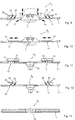
- a source outlet R has a base plate 1, which is rectangular in the present exemplary embodiment.
- a lighting device 2 is preferably inserted in the center of this base plate 1.
- the lighting device 2 has a housing 3 made of end walls 4, 5 and side walls 6, 7, which are connected to a cover 8.
- At least one lamp 9, in particular fluorescent tube, is inserted into the housing 3 of the lamp device 2, which is open at the bottom.
- the inner surfaces of the end walls 4, 5 or side walls 6, 7, not numbered here, can be designed as reflectors. It is also conceivable here to use other lights, for example light bulbs, halogen lights or the like.
- outlet openings 10, 11 are formed in the base plate 1. Supply air flows into a room through these outlet openings 10, 11. Perforated plates 12, 13 in the base plate 1 form the outlet openings 10, 11, on the one hand to swell a flow and on the other hand to act as a screen.
- corresponding outlet openings or perforated plates can be provided in addition to the end walls 4, 5 of the lighting device 2.
- the source outlet and in particular the base plate 1 round, square but also elongated.
- the lighting device is adapted to the shape of the source outlet or the base plate 1. Then the outlet opening or perforated plate is arranged in a ring around the lamp.
- FIG. 2 shows how the lighting device 2 is inserted into the base plate 1 of the source outlet R, the side walls 6, 7 of which are directed inwards.
- An outer and peripheral edge 14 of the base plate 1 lies against a ceiling or wall, not shown here.
- the outlet openings 10, 11 or the perforated plate 12, 13 point downward.
- the lighting device 2 is also open at the bottom or can be provided by means of light deflection slats, not shown here.
- the housing 3 of the lighting device 2 is directed inwards, the side walls 6, 7 being inclined obliquely outwards, as shown in FIG. 2. In this position of the lighting device 2, air can flow through the perforated plates 12, 13 into a room.
- the lighting device 2 of the source outlet R is inserted into the base plate 1 in a height-adjustable manner.
- the lighting device 2 of the source outlet R is therefore extended downward and forms additional air outlet openings 15, 16, the size of which can be changed by moving the lighting device 2 downward in the double arrow direction x shown, since the side walls 6, 7 of the Luminous device 2 run at an angle.
- an air guide jet 17, 18, shown as arrows is discharged into a room through the obliquely positioned side walls 6, 7.
- the guide jet 17, 18 can be applied horizontally to a ceiling.
- the air guide jet 17, 18 can be regulated in relation to the volume flow passing through the outlet openings 10, 11 of the perforated plates. A swelling effect of the air jet to be introduced into a room is supported.
- the air outlet devices 10, 11, which are arranged next to the lighting device 2 in the manner described above, are followed by air deflection devices 21, 22 on the inside.
- These can have a plurality of adjustable slats 23.
- These adjustable slats 23 have the effect that an air flow, for example, can be introduced directly vertically downward through the outlet openings 10, 11 into a surrounding space. In this case, the lighting device 2 just closes with the base plate 1. If an air flow to the right or to the left is desired, the corresponding slats 23 of the air steering device 21, 22 can be adjusted in a manual, electrical, mechanical or similar manner.
- slats 23 can also be directed inwards towards the lighting device 2, as is indicated in FIG. 5. An exact adjustment of the air flow to a point in the room is possible here.
- the lighting device 2 can be moved downward in the X direction shown, so that, as described above, the air guide jet 17, 18 shown as an arrow emerges from the source outlet R 1 .
- a swirling air flow can be achieved in that, for example, the fins 23 are aligned such that an air flow strikes the air guide jet 17, 18.
- a swelling and swirling discharge of air flows can be regulated.
- the slats 23 can also be oriented obliquely outwards, in accordance with the direction of the air guide jet 17 or 18, in order to apply an exclusively horizontal flow to a ceiling.
- the volume flow flowing through the air steering device 21, 22 can be deflected by the slats 24 connected downstream of the slats 23. These are preferably arranged at an angle of approximately 90 ° to the slats 23.
- FIGS. 6 and 7. Another exemplary embodiment of a source outlet R 2 is described in FIGS. 6 and 7.
- the lighting device 2 is movably inserted into the base plate 1, air outlet devices 25, 26 being connected downstream of the outlet openings 10, 11 to the right and left of the lighting device 2.
- These have fins 23 which can deflect the air flow in accordance with the exemplary embodiments in FIGS. 4 and 5.
- slot slides 27 are of a conventional type. They have a large number of lamellae lying next to one another and not shown in detail here. These slit slides 27 can partially but completely close slots in a rear wall, as described in DE-OS 39 07 559.1. A swelling outlet R 2 is created , which can prevent a flow if the slit slides 27 close the outlet openings 10, 11 and the lighting device 2 the air outlet openings 15, 16.
- air guide jets 17, 18 can be introduced into a room, which preferably lie against a ceiling.
- these slit slides 27 also allow unilateral control.
- only the right-hand air steering device 26 or only the left-hand air steering device 27 can be fully or partially opened by the slit slide 26 or 27 in order to introduce a flow into a room only to the right or only to the left.
- a source outlet R 3 is provided with profiled air steering elements 28, 29, which are connected downstream of the base plate 1 and in particular the outlet openings 10, 11 of the source outlet R 3 .
- these air-directing elements 28, 29 are directed outwards.
- Several such profiled air directing elements 28, 29 can be arranged in the area of the outlet opening 10, 11. These support and stabilize the air guide jet 17, 18, which is deflected along the side walls 6, 7 of the lighting device 2.
- outlet openings 10, 11 of a further source outlet R 4 can be opened or partially or completely closed by means of slotted slides 31, 32.
- the slit slides 31, 32 have slats which are not numbered in detail and which are inclined and which can deflect an air flow in a very specific direction.
- the lighting device 2 can also be moved downward and an air guide jet can be deflected accordingly in the manner described above.
- a smoke detector 33 is inserted in the center of a base plate 1.1 of a source outlet R 5 .
- the outlet openings 10, 11 are formed in the base plate 1.1.
- These slats 23 can be adjusted in other directions in order to direct an air flow directly to specific locations in a room.
- this source outlet R 5, in particular the outlet openings 10, 11, can also be followed by a wide variety of different air guiding devices, as may also be described above, in order to regulate or deflect a flow.
- a movement outlet 34 is assigned to a source outlet R 6 according to FIG. 12 instead of the smoke detector 33. This sits in the middle of the base plate 1.1.
- air outlet elements 28, 29, optionally supported via the joints 30, are connected upstream of the outlet openings 10, 11 in the manner described above.
- a loudspeaker 35 is preferably inserted centrally in a source outlet R 7 and in particular in its base plate 1.2.
- outlet openings with air guiding elements or the like can be arranged next to the loudspeaker 35 in a manner described several times in accordance with the source outlets R to R 6 .
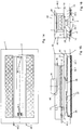
- FIG. 14 shows a further exemplary embodiment of a swelling outlet R 8 according to the invention.
- This also has a base plate 1, into which a lighting device 2 according to FIGS. 1 to 10 is inserted. Instead of the lights, only the corresponding plug connections 36.1 and 36.2 can be seen here.
- the corresponding lines 37 and a distributor 38 are also indicated.
- the strip-shaped perforated plates 12 and 13 are located in the base plate 1, to which air-directing elements 28 and 29 according to FIGS. 8 to 12 are placed.
- the air steering elements on the left of the lighting device 2 are movable, the air steering elements on the right of the lighting device 2 are fixed.
- the perforated plates 12 and 13 are placed in front of the perforated plate strips 39.1 and 39.2, which are at least partially laterally bent upwards. These are fastened to corresponding holding rails 40.1 and 40.2, a guide slot 41 being provided which ensures that the perforated sheet strips 39.1 and 39.2 can be displaced laterally in relation to the lighting device 2.
- the lighting device 2 is enclosed by a housing 42.
- An inlet connection 44 for supply air is inserted into a rear wall 43 of the housing 42.
- This inlet connector 44 opens into a chamber 45 which is delimited by a corresponding wall 46.
- a cooling device 47 which can also be referred to as a cooling baffle.
- Cooling water is supplied to and removed from the cooling device 47 via corresponding lines 48.1 or 48.2.
- a perforated sheet metal cage 48 is provided between the cooling device 47 and the inlet connector 44, which is used to distribute the supply air emerging from the inlet connector 44 via the cooling device 47 and into adjoining rooms 49.1 and 49.2.
- the chamber 45 opens out above the lighting device 2 into an outlet chamber 50, in which the lighting device 2 and also the air steering elements 28 and 29 are seated.
- the outlet chamber 50 is separated from the secondary chambers 49.1 and 49.2 by a central wall 51.
Landscapes
- Engineering & Computer Science (AREA)
- Chemical & Material Sciences (AREA)
- Combustion & Propulsion (AREA)
- Mechanical Engineering (AREA)
- General Engineering & Computer Science (AREA)
- Duct Arrangements (AREA)
- Arrangement Of Elements, Cooling, Sealing, Or The Like Of Lighting Devices (AREA)
- Percussion Or Vibration Massage (AREA)
- Glass Compositions (AREA)
- Compressor (AREA)
Abstract
Bei einem Quellauslass zum Einbringen von Luft in einen Raum, aus einer Grundplatte (1, 1.1, 1.2), in welcher zumindest eine Auslassöffnung (10, 11) vorgesehen ist, soll der Grundplatte (1) zumindest eine Leuchteinrichtung (2) und/oder Rauchmelder (33) und/oder Bewegungsmelder (34) und/oder Lautsprecher (35) zugeordnet sein.
Description
Die vorliegende Erfindung betrifft einen Quellauslass zum Einbringen von Luft in einen Raum, aus einer Grundplatte, in welcher zumindest eine Auslassöffnung vorgesehen ist.The present invention relates to a source outlet for introducing air into a room, from a base plate in which at least one outlet opening is provided.
Quellauslässe werden heute meist am oder in dem Boden eingebaut, d. h., direkt in der Aufenthaltszone. Dies ist teuer und nimmt Platz weg.Spring outlets are now mostly installed on or in the floor, i. that is, directly in the lounge area. This is expensive and takes up space.
Auf dem Markt sind Quellauslässe in vielfältigster Form und Ausführung bekannt. Mit ihnen wird Luft in einen Raum eingebracht, ohne dass grosse Zugerscheinungen entstehen. Nachteilig an den Quellauslässen ist, dass diese Strömungen nur in ganz bestimmte Richtungen zulassen und sich nur schlecht regeln lassen.Source outlets in a wide variety of shapes and designs are known on the market. They are used to introduce air into a room without causing major drafts. A disadvantage of the source outlets is that these flows only allow in very specific directions and are difficult to control.
Ferner ist nachteilig, dass sich bei herkömmlichen Quellauslässen ein Luftstrom nur schlecht regeln und in bestimmte Richtungen einstellen lässt.Another disadvantage is that with conventional source outlets, an air flow is difficult to regulate and can be adjusted in certain directions.
In moderne Gebäude ist eine Vielzahl von Einrichtungen, wie Auslässe, Beleuchtungsanlagen, Sicherheits- und Warneinrichtungen, wie bspw. Bewegungs- oder Rauchmelder, und Lautsprecher od. dgl. vorgesehen, um den heutigen Ansprüchen zu genügen. Dafür sind viele Firmen notwendig, welche für die unterschiedlichen Aufgaben, wie Installation der Lüftung bzw. die Klimatisierung des Gebäudes, für die Beleuchtung und für die Sicherheit zuständig sind. Daher wird auch eine Vielzahl unnötiger Montageleistungen doppelt erbracht, um die einzelnen Geräte anzuschliessen, was erhebliche Kosten verursacht. Gerade dies ist auf dem heutigen Markt von grossem Nachteil, da durch hohe Montagekosten vieler Firmen in den o.g. Bereichen die Baukosten zu hoch ausfallen.In modern buildings, a large number of facilities, such as outlets, lighting systems, safety and warning devices, such as, for example, motion or smoke detectors, and loudspeakers or the like are provided in order to meet today's requirements. This requires many companies that are responsible for the various tasks, such as installing the ventilation or air conditioning of the building, for lighting and for security. Therefore, a multitude of unnecessary assembly work is performed twice to connect the individual devices, which causes considerable costs. This is a major disadvantage in today's market, as the high assembly costs of many companies in the above mentioned Areas of construction costs are too high.
Der Erfindung liegt die Aufgabe zugrunde, die o.g. Nachteile zu beseitigen und einen Deckenquellauslass zu schaffen, welcher es ermöglicht die Luft in bestimmte Richtungen zu lenken. Dabei sollen auch die Montagekosten reduziert werden.The invention has for its object the above. Eliminate disadvantages and create a ceiling source outlet, which allows the air to be directed in certain directions. The assembly costs should also be reduced.
Zur Lösung dieser Aufgabe führt, dass der Grundplatte zumindest eine Leuchteinrichtung und/oder ein Rauchmelder und/oder Bewegungsmelder und/oder Lautsprecher zugeordnet ist.To achieve this object, the base plate is assigned at least one lighting device and / or a smoke detector and / or motion detector and / or loudspeaker.
Bei der vorliegenden Erfindung sind in eine Grundplatte Auslassöffnungen bevorzugt als Lochbleche eingestanzt, wobei der Grundplatte zusätzlich eine Leuchte zugeordnet ist. Diese Leuchte ist bevorzugt mittig in die Grundplatte eingesetzt und kann vertikal zur Grundplatte bewegt werden. Durch bevorzugt schräg geneigte Seitenflächen der Leuchte, entstehen beim vertikalen Bewegen der Leuchteinrichtung nach unten seitlich Luftauslassöffnungen, durch welche ein Luftleitstrahl ausgebracht werden kann.In the present invention, outlet openings are preferably punched into a base plate as perforated plates, a base lamp being additionally associated with a lamp. This lamp is preferably inserted in the center of the base plate and can be moved vertically to the base plate. Due to the preferably obliquely inclined side surfaces of the lamp, when the lamp device is moved vertically downward, air outlet openings are created through which an air guide jet can be discharged.
Wird die Leuchteinrichtung nach oben in Richtung Grundplatte bewegt, so minimiert sich die Luftauslassöffnung, so dass ein Volumenstrom geregelt werden kann. Durch die schräg geneigten Seitenwände des Gehäuses der Leuchteinrichtung wird der austretende Volumenstrom horizontal abgelenkt.If the lighting device is moved upwards in the direction of the base plate, the air outlet opening is minimized so that a volume flow can be regulated. The emerging volume flow is deflected horizontally by the inclined side walls of the housing of the lighting device.
Ist dies nicht erwünscht, so können den Auslassöffnungen bzw. den Lochblechen Luftlenkeinrichtungen herkömmlicher Art vorgeschaltet werden. Diese bestehen bspw. aus verschwenkbaren Lamellen, Schlitzschiebern, profilierten Luftlenkelementen od. dgl.. Sie lenken einen Luftstrom nach unten, aber auch nach innen oder nach aussen seitlich ab, wobei durch jede Luftlenkeinrichtung separat sich ein Luftstrom ablenken bzw. einstellen lässt. Dieses Einstellen kann manuell aber auch automatisch erfolgen.If this is not desired, then air outlet devices of a conventional type can be connected upstream of the outlet openings or the perforated plates. These consist, for example, of pivotable slats, slider slides, profiled air steering elements or the like. They deflect an air flow downwards, but also laterally inwards or outwards, with each air steering device being able to deflect or adjust an airflow separately. This setting can be done manually or automatically.
Hier ist ein Quellauslass gebildet, welcher vielfältigste Möglichkeiten der Luftregelung und der Luftführung zulässt.A source outlet is formed here, which allows a wide variety of options for air control and air routing.
Damit möglichst viele unterschiedliche Quellauslässe Anwendung finden, kann die Grundplatte quadratisch, rechteckartig, rund oder anderswie ausgebildet sein. Bevorzugt ist die Leuchteinrichtung mittig in der Grundplatte angeordnet, wobei neben dieser bzw. um diese herum die Auslassöffnungen angeordnet sind.So that as many different source outlets as possible are used, the base plate can be square, rectangular, round or otherwise. The lighting device is preferably arranged in the center of the base plate, the outlet openings being arranged next to it or around it.
Anstelle oder auch neben der Leuchteinrichtung können auch Bewegungs- oder Rauchmelder bzw. Lautsprecher in der Grundplatte vorgesehen sein, wobei in oben beschriebener Weise, diese Elemente von Auslassöffnungen umgeben sind. Hinter diesen Auslassöffnungen sind ebenfalls Luftlenkeinrichtungen vorgesehen, welche einen Volumenstrom entweder gerade nach unten oder in x-beliebiger Weise, auch bis zur Horizontalen, in einen Raum ausbringen können.Instead of or in addition to the lighting device, motion or smoke detectors or loudspeakers can also be provided in the base plate, these elements being surrounded by outlet openings in the manner described above. Air deflection devices are also provided behind these outlet openings, which can deliver a volume flow into a room either straight downwards or in any way, even up to the horizontal.
Ein weiterer wesentlicher Vorteil der vorliegenden Erfindung ist, dass auch alle Elemente, wie Lautsprecher, Bewegungs- bzw. Rauchmelder in der Grundplatte vorgesehen sein können und einen Quellauslass schaffen, welcher universell einsetzbar ist. Viele Arbeitsgänge, wie bspw. das Verlegen von Leitungen und dgl., werden so durch einen Quellauslass eingespart. Nur eine Firma und nur ein Quellauslass ist notwendig, um die Montage von Belüftung, Beschallung, Beleuchtung usw. vorzunehmen.Another important advantage of the present invention is that all elements, such as loudspeakers, motion detectors or smoke detectors, can also be provided in the base plate and create a source outlet which can be used universally. Many operations, such as the laying of lines and the like, are saved by a source outlet. Only one company and only one source outlet is required to install ventilation, sound, lighting, etc.
Einer weiteren Beeinflussung der aus der Grundplatte austretenden Luftströmung dienen auch zusätzliche Lochblechstreifen, welche den oben erwähnten Auslassöffnungen vorgesetzt sein können. Bspw. können diese Lochblechstreifen seitlich aufgewölbt sein, so dass ein Luftstrom zu bspw. der Leuchteinrichtung hin ausquellen kann und hier für einen schnelleren Wärmeabbau sorgt.Additional perforated sheet strips, which can be placed in front of the outlet openings mentioned above, also serve to influence the air flow emerging from the base plate. E.g. These perforated metal strips can be curved laterally, so that an air stream can swell out, for example towards the lighting device, and ensure faster heat dissipation here.
Diese zusätzlichen Lochblechstreifen sollen über Halteschienen mit der Grundplatte verbunden sein. Dabei ist erfindungsgemäss vorgesehen, diese Verbindung so auszugestalten, dass die Lochblechstreifen seitlich, z.B. in Richtung einer Leuchteinrichtung hin, bewegbar sind.These additional perforated metal strips should be connected to the base plate via holding rails. It is provided according to the invention to design this connection so that the perforated metal strips on the side, e.g. are movable in the direction of a lighting device.
Desweiteren ist vorgesehen, dass der Grundplatte ein Gehäuse aufgesetzt ist, welches bspw. die Leuchteinrichtung umgibt. Erfindungsgemäss soll in ein derartiges Gehäuse eine Kühleinrichtung eingesetzt sein, die entsprechende Anschlüsse zum Zu- und Abführen eines Kühlmediums aufweist. Hierdurch kann der erfindungsgemässe Quellauslass anstelle einer Kühldecke Anwendung finden. Es besteht die Möglichkeit mit Hilfe der als Kühlbaffle ausgebildeten Kühleinrichtung gekühlte Zuluft grossflächig über eine Raumfläche zu verteilen. Dadurch ist es möglich, die Zuluft zugfrei dem Raum zuzuführen. Der gesamte Raum wird mit frischer, kühler Luft versorgt, so dass im Raum ein angenehmes Klima herrscht.Furthermore, it is provided that a housing is placed on the base plate, which, for example, surrounds the lighting device. According to the invention, a cooling device is to be inserted into such a housing, which has corresponding connections for supplying and removing a cooling medium. As a result, the source outlet according to the invention can be used instead of a cooling ceiling. It is possible to use the cooling device designed as a cooling baffle to distribute cooled supply air over a large area over a room area. This makes it possible to supply the air to the room without drafts. The entire room is supplied with fresh, cool air so that the room has a pleasant climate.
Die Nachteile der Kühldecken, die vor allem darin liegen, dass Kühldecken ohne Zusatzlüftung nicht funktionell sind, werden durch die vorliegende Erfindung beseitigt.The disadvantages of the cooling ceilings, which lie primarily in the fact that cooling ceilings are not functional without additional ventilation, are eliminated by the present invention.
Der vorliegende Quellauslass gestattet es, dass die durch die Kühleinrichtung abgekühlte Zuluft nicht senkrecht nach unten auf eine relativ kleine Fläche fällt, so dass eine bspw. in dem Raum vorhandene Wärmequelle, wie z.B. ein PC, die eingebrachte kühle Luft von der Wärmequelle wegdrückt. Diese kühle Luft wandert dann irgendwo völlig unkontrolliert in eine Ecke des Raumes. Durch den erfindungsgemässen Quellauslass werden diese Zugerscheinungen und vor allem der Nachteil, dass nur ein kleiner Teil des Raumes mit Frischluft versorgt wird, vermieden.The present source outlet allows the supply air cooled by the cooling device not to fall vertically downward onto a relatively small area, so that a heat source, e.g. a PC that pushes the cool air introduced away from the heat source. This cool air then moves somewhere completely uncontrolled into a corner of the room. These draft phenomena and, above all, the disadvantage that only a small part of the space is supplied with fresh air are avoided by the swelling outlet according to the invention.
Mit dem Quellauslass und der Kühleinrichtung wird ein Kombinationsauslass geschaffen, der die gesamte Raumfläche gleichmässig mit frischer Luft versorgen kann. Hervorzuheben ist ausserdem eine leichte Montage, da nicht unterschiedliche Montagefirmen beauftragt werden müssen, welche die Leuchten, die Lüftung, die Kühleinrichtung, den Rauchmelder, den Bewegungsmelder oder den Lautsprecher montieren.With the source outlet and the cooling device, a combination outlet is created that can supply the entire room area with fresh air. It should also be emphasized that it is easy to install, since it is not necessary to commission different assembly companies to install the lights, ventilation, cooling equipment, smoke detectors, motion detectors or loudspeakers.
Ein weiterer grosser Vorteil liegt darin, dass die Kühleinrichtung mit einem Kühlmedium versorgt wird, wobei durch ein Ventil und einen Thermostat die Zuflussmenge des Kühlmediums leicht festgelegt werden kann, so dass jede gewünschte Temperatur ohne grosse Probleme erreicht wird. Bevorzugt wird das Medium in Behältern aufbewahrt, so dass auch das erwärmte Medium diesem Behälter zugeführt werden kann. Dieser Behälter kann dann wiederum an eine Wärmepumpe angeschlossen sein, die Warmwasser erzeugt und dabei das Kühlwasser wieder abkühlt, so dass dieses im Kreislauf geführt werden kann.Another great advantage is that the cooling device is supplied with a cooling medium, wherein the inflow amount of the cooling medium can be easily determined by a valve and a thermostat, so that any desired temperature is reached without major problems. The medium is preferably stored in containers so that the heated medium can also be supplied to this container. This container can then in turn be connected to a heat pump that generates hot water and cools the cooling water again so that it can be recycled.
Weitere Vorteile, Merkmale und Einzelheiten der Erfindung ergeben sich aus der nachfolgenden Beschreibung bevorzugter Ausführungsbeispiele sowie anhand der Zeichnung; diese zeigt in
Figur 1 eine Draufsicht auf einen erfindungsgemässen Quellauslass;Figur 2 einen schematisch dargestellten Querschnitt des Quellauslasses gemässFigur 1;Figur 3 einen Querschnitt durch den Quellauslass gemäss denFiguren 1 und 2 in einer anderen Gebrauchslage;Figur 4 einen Querschnitt durch ein weiteres Ausführungsbeispiel des Quellauslasses gemässFigur 1;Figur 5 einen Querschnitt durch den Quellauslass gemässFigur 4 in einer anderen Gebrauchslage;Figur 6 einen Querschnitt durch den Quellauslass gemässFigur 1 als weiteres Ausführungsbeispiel;Figur 7 einen Querschnitt durch den Quellauslass gemässFigur 6 in einer anderen Gebrauchslage;Figur 8 einen Querschnitt durch den Quellauslass gemässFigur 1 als weiteres Ausführungsbeispiel;Figur 9 einen Querschnitt durch den Quellauslass gemässFigur 8 in einer anderen Gebrauchslage;Figur 10 einen Querschnitt durch ein weiteres Ausführungsbeispiel des Quellauslasses gemässFigur 1;Figur 11 einen Querschnitt durch ein weiteres Ausführungsbeispiel eines Quellauslasses mit einem Rauchmelder;Figur 12 einen Querschnitt durch ein weiteres Ausführungsbeispiel des Quellauslasses mit einem Bewegungsmelder;Figur 13 einen Querschnitt durch einen Quellauslass mit Lautsprecher.- Figur 14 eine Draufsicht auf ein weiteres Ausführungsbeispiel eines erfindungsgemässen Quellauslasses;
Figur 15 einen Längsschnitt durch den Quellauslass gemäss Figur 14;Figur 16 einen Querschnitt durch den Quellauslass gemäss Figur 14.
- Figure 1 is a plan view of a source outlet according to the invention;
- FIG. 2 shows a schematically illustrated cross section of the source outlet according to FIG. 1;
- 3 shows a cross section through the source outlet according to FIGS. 1 and 2 in a different position of use;
- FIG. 4 shows a cross section through a further exemplary embodiment of the source outlet according to FIG. 1;
- FIG. 5 shows a cross section through the source outlet according to FIG. 4 in a different position of use;
- FIG. 6 shows a cross section through the source outlet according to FIG. 1 as a further exemplary embodiment;
- FIG. 7 shows a cross section through the source outlet according to FIG. 6 in another position of use;
- FIG. 8 shows a cross section through the source outlet according to FIG. 1 as a further exemplary embodiment;
- FIG. 9 shows a cross section through the source outlet according to FIG. 8 in a different position of use;
- FIG. 10 shows a cross section through a further exemplary embodiment of the source outlet according to FIG. 1;
- FIG. 11 shows a cross section through a further exemplary embodiment of a source outlet with a smoke detector;
- FIG. 12 shows a cross section through a further exemplary embodiment of the source outlet with a motion detector;
- 13 shows a cross section through a source outlet with loudspeaker.
- FIG. 14 shows a plan view of a further exemplary embodiment of a source outlet according to the invention;
- FIG. 15 shows a longitudinal section through the source outlet according to FIG. 14;
- FIG. 16 shows a cross section through the source outlet according to FIG. 14.
Gemäss Figur 1 weist ein erfindungsgemässer Quellauslass R eine Grundplatte 1 auf, welche im vorliegenden Ausführungsbeispiel rechteckartig ausgebildet ist. In diese Grundplatte 1 ist bevorzugt mittig eine Leuchteinrichtung 2 eingesetzt. Dabei weist die Leuchteinrichtung 2 ein Gehäuse 3 aus Stirnwänden 4, 5, und Seitenwänden 6, 7 auf, welche mit einem Deckel 8 verbunden sind. In das nach unten geöffnete Gehäuse 3 der Leuchteinrichtung 2 ist zumindest eine Leuchte 9, insbesondere Leuchtstoffröhre, eingesetzt. Die hier nicht bezifferten Innenflächen der Stirnwände 4, 5 bzw. Seitenwände 6, 7, können als Reflektoren ausgebildet sein. Auch hier ist denkbar, andere Leuchten bspw. Glühbirnen, Halogenleuchten od. dgl. einzusetzen.According to FIG. 1, a source outlet R according to the invention has a
Neben der Leuchteinrichtung 2 sind in die Grundplatte 1 Auslassöffnungen 10, 11 eingeformt. Durch diese Auslassöffnungen 10, 11 strömt Zuluft in einen Raum. Lochbleche 12, 13 in der Grundplatte 1 bilden die Auslassöffnungen 10, 11, um eine Strömung einerseits zu verquellen und andererseits als Sichtschutz zu wirken.In addition to the
Im Rahmen der vorliegenden Erfindung liegt jedoch auch, dass neben den Stirnwänden 4, 5 der Leuchteinrichtung 2 entsprechende Auslassöffnungen bzw. Lochbleche vorgesehen sein können. Ferner ist daran gedacht, den Quellauslass und insbesondere die Grundplatte 1 rund, quadratisch aber auch länglich auszubilden. Im Falle einer runden Ausführung des Quellauslasses ist die Leuchteinrichtung der Form des Quellauslasses bzw. der Grundplatte 1 angepasst. Dann sind auch Auslassöffnung bzw. Lochblech kreisringartig um die Leuchte angeordnet.However, it is also within the scope of the present invention that corresponding outlet openings or perforated plates can be provided in addition to the
In Figur 2 ist dargestellt, wie die Leuchteinrichtung 2 in die Grundplatte 1 des Quellauslasses R eingesetzt ist, wobei deren Seitenwände 6, 7 nach innen gerichtet sind. Eine äussere und umlaufende Randkante 14 der Grundplatte 1 liegt an einer hier nicht gezeigten Decke oder Wand an. In diesem Fall zeigen dann die Auslassöffnungen 10, 11 bzw. das Lochblech 12, 13 nach unten. Auch die Leuchteinrichtung 2 ist nach unten geöffnet oder kann mittels hier nicht dargestellten Lichtlenklamellen versehen sein. Das Gehäuse 3 der Leuchteinrichtung 2 ist nach innen gerichtet, wobei wie in Figur 2 dargestellt, die Seitenwände 6, 7 schräg nach aussen geneigt sind. In dieser Lage der Leuchteinrichtung 2 kann Luft durch die Lochbleche 12, 13 in einen Raum einströmen.FIG. 2 shows how the
Erfindungsgemäss ist die Leuchteinrichtung 2 des Quellauslasses R höhenverstellbar in die Grundplatte 1 eingesetzt. In einer weiteren Gebrauchslage gemäss Figur 3 ist deshalb die Leuchteinrichtung 2 des Quellauslasses R nach unten ausgefahren und bildet zusätzliche Luftauslassöffnungen 15, 16, deren Grösse durch ein Verfahren der Leuchteinrichtung 2 nach unten in dargestellter Doppelpfeilrichtung x veränderbar ist, da die Seitenwände 6, 7 der Leuchteinrichtung 2 schräg verlaufen. Gleichzeitig wird durch die schräg angestellten Seitenwände 6, 7 ein Luftleitstrahl 17, 18, als Pfeile dargestellt, in einen Raum ausgebracht.According to the invention, the
Durch diesen Luftleitstrahl 17, 18 und ggf. auch durch untere Randkanten 19, 20 des Gehäuses 3 der Leuchteinrichtung 2 lässt sich der Leitstrahl 17, 18 horizontal an einer Decke anlegen.By means of this
Je grösser die Luftauslassöffnungen 15, 16, desto grösser ist auch das Luftvolumen, welches durch diese Öffnungen strömen kann.Insofern lässt sich der Luftleitstrahl 17, 18 im Verhältnis zu dem durch die Auslassöffnungen 10, 11 der Lochbleche tretenden Volumenstroms regeln. Eine verquellende Wirkung des in einen Raum einzubringenden Luftstrahles wird unterstützt.The larger the
In einem weiteren Ausführungsbeispiel einem Quellauslasses R1 der vorliegenden Erfindung gemäss Figur 4 sind den Auslassöffnungen 10, 11, welche in oben beschriebener Weise neben der Leuchteinrichtung 2 angeordnet sind, Luftlenkeinrichtungen 21, 22 innen nachgeschaltet. Diese können eine Mehrzahl von verstellbar angeordneten Lamellen 23 aufweisen. Diese verstellbar angeordneten Lamellen 23 bewirken, dass eine Luftströmung bspw. direkt vertikal nach unten durch die Auslassöffnungen 10, 11 in einen umgebenden Raum eingebracht werden kann. In diesem Fall schliesst die Leuchteinrichtung 2 eben mit der Grundplatte 1 ab. Wird eine Luftströmung nach rechts oder nach links gewünscht, so können die entsprechenden Lamellen 23 der Luftlenkeinrichtung 21, 22 auf manuelle, elektrische, mechanische oder ähnliche Weise angestellt werden.In a further exemplary embodiment of a source outlet R 1 of the present invention according to FIG. 4, the
Auch können diese Lamellen 23 nach innen zur Leuchteinrichtung 2 hin gerichtet sein, wie es in Figur 5 angedeutet ist. Eine exakte auf einen Raumpunkt ausgerichtete Einstellen der Luftströmung ist hier möglich. Zusätzlich kann, wie in Figur 3 beschrieben, die Leuchteinrichtung 2 nach unten in dargestellter X-Richtung bewegt werden, so dass, wie oben beschrieben, der als Pfeil dargestellte Luftleitstrahl 17, 18 aus dem Quellauslass R1 austritt.These
Eine verwirbelnde Luftströmung kann dadurch erreicht werden, dass bspw. die Lamellen 23 so ausgerichtet sind, dass ein Luftstrom auf den Luftleitstrahl 17, 18 trifft. Auch hier ist ein quellendes und verwirbelndes Ausbringen von Luftströmungen regelbar. Selbstverständlich können die Lamellen 23 auch schräg nach aussen, entsprechend der Richtung des Luftleitstrahles 17 bzw. 18, ausgerichtet sein, um eine ausschliesslich horizontale Strömung an eine Decke anzulegen.A swirling air flow can be achieved in that, for example, the
Ferner lässt sich der durch die Luftlenkeinrichtung 21, 22 strömende Volumenstrom durch den Lamellen 23 nachgeschaltete Lamellen 24 ablenken. Diese sind bevorzugt im Winkel von ca. 90o zu den Lamellen 23 angeordnet.Furthermore, the volume flow flowing through the
Ein weiteres Ausführungsbeispiel eines Quellauslasses R2 ist in den Figuren 6 und 7 beschrieben. Dort ist in die Grundplatte 1, wie oben beschrieben, die Leuchteinrichtung 2 bewegbar eingesetzt, wobei rechts und links neben der Leuchteinrichtung 2 den Auslassöffnungen 10, 11 Luftlenkeinrichtung 25, 26 nachgeschaltet sind. Diese weisen Lamellen 23 auf, welche die Luftströmung entsprechend den Ausführungsbeispielen der Figuren 4 und 5 ablenken können.Another exemplary embodiment of a source outlet R 2 is described in FIGS. 6 and 7. There, as described above, the
Diesen Lamellen 23 sind Schlitzschieber 27 nachgeschaltet, welche herkömmlicher Art sind. Sie weisen eine Vielzahl von nebeneinanderliegenden und hier nicht näher dargestellten Lamellen auf. Diese Schlitzschieber 27 können durch entsprechendes Verschieben Schlitze in einer Rückwand teilweise aber auch völlig verschliessen, wie dies in der DE-OS 39 07 559.1 beschrieben ist. Es entsteht ein Quellauslass R2, welcher eine Strömung unterbinden kann, wenn die Schlitzschieber 27 die Auslassöffnungen 10, 11 und die Leuchteinrichtung 2 die Luftauslassöffnungen 15, 16 verschliessen.These
Bspw. bei nur verschlossenen Schlitzschiebern 27 können dagegen, wenn gewünscht, Luftleitstrahlen 17, 18 in einen Raum eingebracht werden, welche sich bevorzugt an einer Decke anlegen.E.g. if the slit slides 27 are only closed, on the other hand, if desired,
Jedoch lassen diese Schlitzschieber 27 auch eine einseitige Regelung zu. Bspw. kann nur die rechte Luftlenkeinrichtung 26 oder nur die linke Luftlenkeinrichtung 27 ganz oder teilweise durch den Schlitzschieber 26 oder 27 geöffnet sein, um ggf. eine Strömung nur nach rechts oder nur nach links in einen Raum einzubringen. Hier sind sehr viele Möglichkeiten der Einstellungen der Luftströmungen denkbar.However, these slit slides 27 also allow unilateral control. E.g. For example, only the right-hand
In den Figuren 8 und 9 ist ein Quellauslass R3 mit profiliert ausgebildeten Luftlenkelementen 28, 29 versehen, welche der Grundplatte 1 und insbesondere den Auslassöffnungen 10, 11 des Quellauslasses R3 nachgeschaltet sind. Diese Luftlenkelemente 28, 29 sind in diesem Ausführungsbeispiel nach aussen gerichtet. Dabei können mehrere solcher profilierter Luftlenkelemente 28, 29 im Bereich der Auslassöffnung 10, 11 angeordnet sein. Diese unterstützen und stabilisieren gleichzeitig den Luftleitstrahl 17, 18, welcher entlang der Seitenwände 6, 7 der Leuchteinrichtung 2 abgelenkt wird.In FIGS. 8 and 9, a source outlet R 3 is provided with profiled
Auch ist denkbar, wie es in Figur 9 angedeutet ist, diese Luftlenkelemente 28, 29 über Gelenke 30 zu verdrehen, so dass ein Ausströmen des Luftstromes beeinflusst und ggf. geregelt werden kann. Ferner können eine Mehrzahl solcher Luftlenkelemente 28, 29 den Auslassöffnungen 10 bzw. 11 nachgeschaltet sein.It is also conceivable, as is indicated in FIG. 9, to rotate these
Wie in Figur 10 dargestellt, können Auslassöffnungen 10, 11 eines weiteren Quellauslasses R4 mittels Schlitzschieber 31, 32 geöffnet bzw. teilweise oder ganz verschlossen werden.As shown in FIG. 10,
Auch hier weisen die Schlitzschieber 31, 32 nicht näher bezifferte und schräg angestellte Lamellen auf, die eine Luftströmung in eine ganz bestimmte Richtung ablenken können. Auch bei diesem Quellauslass R4 kann die Leuchteinrichtung 2 nach unten bewegt und in oben beschriebener Weise ein Luftleitstrahl entsprechend abgelenkt werden.Here, too, the slit slides 31, 32 have slats which are not numbered in detail and which are inclined and which can deflect an air flow in a very specific direction. With this source outlet R 4 , the
Anstelle der Leuchteinrichtung 2 oder im Anschluss an eine Leuchteinrichtung 2 ist; wie in Fig. 11 dargestellt, mittig ein Rauchmelder 33 in eine Grundplatte 1.1 eines Quellauslasses R5 eingesetzt. Entsprechend den oben beschriebenen Ausführungsbeispielen sind neben dem Rauchmelder 33 die Auslassöffnungen 10, 11 in die Grundplatte 1.1 eingeformt.Instead of the
Diesen können ebenso Luftlenkeinrichtungen 21, 22 nachgeschaltet sein, deren Lamellen 23 bspw. nach innen gerichtet sind, um eine Luftströmung in eine bestimmte Richtung in einen Raum einzubringen. Diese Lamellen 23 können in andere Richtungen verstellt werden, um eine Luftströmung direkt auf bestimmte Orte eines Raumes auszurichten.These can also be followed by air-directing
Ferner können auch diesem Quellauslass R5 insbesondere den Auslassöffnungen 10, 11 unterschiedlichste, wie auch ggf. oben beschriebene Luftlenkeinrichtungen nachgeschaltet sein, um eine Strömung zu regeln bzw. abzulenken.Furthermore, this source outlet R 5, in particular the
In entsprechend oben beschriebener Weise ist einem Quellauslass R6 gemäss Fig. 12 anstelle des Rauchmelders 33 ein Bewegungsmelder 34 zugeordnet. Dieser sitzt mittig in der Grundplatte 1.1. Auch hier sind den Auslassöffnungen 10, 11 Luftlenkelemente 28, 29, ggf. über die Gelenke 30 gelagert, in oben beschriebener Weise vorgeschaltet.In a corresponding manner described above, a
In einem letzten Ausführungsbeispiel der vorliegenden Erfindung gemäss Figur 13 ist in einen Quellauslass R7 und ins-besondere in dessen Grundplatte 1.2 ein Lautsprecher 35 be-vorzugt mittig eingesetzt.In a last exemplary embodiment of the present invention according to FIG. 13, a
Dabei können in mehrfach beschriebener Weise entsprechend der Quellauslässe R bis R6 neben dem Lautsprecher 35 Auslassöffnungen mit Luftleitelementen od. dgl. angeordnet sein.In this case, outlet openings with air guiding elements or the like can be arranged next to the
In Figur 14 ist ein weiteres Ausführungsbeispiel eines erfindungsgemässen Quellauslasses R8 gezeigt. Auch dieser besitzt eine Grundplatte 1, in die eine Leuchteinrichtung 2 entsprechend den Figuren 1 bis 10 eingesetzt ist. Anstelle der Leuchten sind hier nur die entsprechenden Steckverbindungen 36.1 und 36.2 erkennbar. Ferner sind die entsprechenden Leitungen 37 und ein Verteiler 38 angedeutet.FIG. 14 shows a further exemplary embodiment of a swelling outlet R 8 according to the invention. This also has a
Gemäss Figur 16 befinden sich in der Grundplatte 1 die streifenförmigen Lochbleche 12 und 13, denen Luftlenkelemente 28 und 29 entsprechend den Figuren 8 bis 12 vorgesetzt sind. Die Luftlenkelemente links der Leuchteinrichtung 2 sind bewegbar, die Luftlenkelemente rechts der Leuchteinrichtung 2 sind feststehend ausgebildet.According to FIG. 16, the strip-shaped
In dem gezeigten Ausführungsbeispiel sind den Lochblechen 12 und 13 nochmals, zumindest teilweise seitlich hochgebogene Lochblechstreifen 39.1 und 39.2 vorgesetzt. Diese sind an entsprechenden Halteschienen 40.1 und 40.2 befestigt, wobei ein Führungsschlitz 41 vorgesehen ist, der gewährleistet, dass die Lochblechstreifen 39.1 und 39.2 im Verhältnis zur Leuchteinrichtung 2 seitlich verschoben werden können.In the exemplary embodiment shown, the
Die Leuchteinrichtung 2 wird von einem Gehäuse 42 umfangen. In eine Rückwand 43 des Gehäuses 42 ist ein Einlassstutzen 44 für Zuluft eingesetzt. Dieser Einlassstutzen 44 mündet in eine Kammer 45, welche von einer entsprechenden Wandung 46 umgrenzt ist. In dieser Kammer 45 befindet sich eine Kühleinrichtung 47, die auch als Kühlbaffle bezeichnet werden kann.The
Über entsprechende Leitungen 48.1 bzw. 48.2 wird Kühlwasser zu der Kühleinrichtung 47 zu- und wieder abgeführt.Cooling water is supplied to and removed from the cooling
Zwischen der Kühleinrichtung 47 und dem Einlassstutzen 44 ist ein Lochblechkäfig 48 vorgesehen, welcher der Verteilung der aus dem Einlassstutzen 44 austretenden Zuluft über die Kühleinrichtung 47 und in Nebenräume 49.1 und 49.2 dient.A perforated
Die Kammer 45 mündet oberhalb der Leuchteinrichtung 2 in eine Auslasskammer 50 aus, in der die Leuchteinrichtung 2 und auch die Luftlenkelemente 28 und 29 sitzen. Dabei ist die Auslasskammer 50 von den Nebenkammern 49.1 und 49.2 durch eine Mittelwand 51 getrennt.The
- 11
- GrundplatteBase plate
- 22nd
- LeuchteinrichtungLighting device
- 33rd
- Gehäusecasing
- 44th
- StirnwandFront wall
- 55
- ""
- 66
- SeitenwandSide wall
- 77
- ""
- 88th
- Deckelcover
- 99
- Leuchtelamp
- 1010th
- AuslassöffnungOutlet opening
- 1111
- ""
- 1212th
- LochblechPerforated sheet
- 1313
- ""
- 1414
- RandkanteEdge
- 1515
- LuftauslassöffnungAir outlet opening
- 1616
- ""
- 1717th
- LuftleitstrahlAir jet
- 1818th
- ""
- 1919th
- RandkantenMarginal edges
- 2020th
- ""
- 2121
- LuftlenkeinrichtungAir steering device
- 2222
- ""
- 2323
- LamellenSlats
- 2424th
- ""
- 2525th
- LuftlenkeinrichtungAir steering device
- 2626
- ""
- 2727
- SchlitzschieberSlit gate valve
- 2828
- LuftlenkelementAir steering element
- 2929
- ""
- 3030th
- Gelenkjoint
- 3131
- SchlitzschieberSlit gate valve
- 3232
- ""
- 3333
- Rauchmeldersmoke detector
- 3434
- Bewegungsmeldermotion detector
- 3535
- Lautsprecherspeaker
- 3636
- SteckverbindungConnector
- 3737
- Leitungencables
- 3838
- VerteilerDistributor
- 3939
- LochblechstreifenPerforated metal strips
- 4040
- HalteschienenHolding rails
- 4141
- FührungsschlitzGuide slot
- 4242
- Gehäusecasing
- 4343
- RückwandBack wall
- 4444
- EinlassstutzenInlet connector
- 4545
- Kammerchamber
- 4646
- WandungWall
- 4747
- KühleinrichtungCooling device
- 4848
- LochblechkäfigPerforated sheet cage
- 48.148.1
- Anschlussconnection
- 48.248.2
- ""
- 4949
- NebenraumAdjoining room
- 5050
- AuslasskammerOutlet chamber
- 5151
- MittelwandMiddle wall
- RR
- QuellauslassSource outlet
- R1 R 1
- ""
- R2 R 2
- ""
- R3 R 3
- ""
- R4 R 4
- ""
- R5 R 5
- ""
- R6 R 6
- ""
- R7 R 7
- ""
- XX
- DoppelpfeilrichtungDouble arrow direction
Claims (26)
dadurch gekennzeichnet,
dass der Grundplatte (1) zumindest eine Leuchteinrichtung (2) und/oder Rauchmelder (33) und/oder Bewegungsmelder (34) und/oder Lautsprecher (35) zugeordnet ist.Source outlet for introducing air into a room, from a base plate (1, 1.1, 1.2) in which at least one outlet opening (10, 11) is provided,
characterized,
that at least one lighting device (2) and / or smoke detector (33) and / or motion detector (34) and / or loudspeaker (35) is assigned to the base plate (1).
Applications Claiming Priority (4)
| Application Number | Priority Date | Filing Date | Title |
|---|---|---|---|
| DE1996117288 DE19617288C2 (en) | 1996-04-30 | 1996-04-30 | Source outlet |
| DE19617288 | 1996-04-30 | ||
| DE19641902 | 1996-10-11 | ||
| DE1996141902 DE19641902C2 (en) | 1996-10-11 | 1996-10-11 | Source outlet |
Publications (3)
| Publication Number | Publication Date |
|---|---|
| EP0805313A2 true EP0805313A2 (en) | 1997-11-05 |
| EP0805313A3 EP0805313A3 (en) | 2000-03-15 |
| EP0805313B1 EP0805313B1 (en) | 2003-11-19 |
Family
ID=26025259
Family Applications (1)
| Application Number | Title | Priority Date | Filing Date |
|---|---|---|---|
| EP97106408A Expired - Lifetime EP0805313B1 (en) | 1996-04-30 | 1997-04-18 | Ventilation outlet |
Country Status (4)
| Country | Link |
|---|---|
| EP (1) | EP0805313B1 (en) |
| AT (1) | ATE254742T1 (en) |
| DE (1) | DE59711016D1 (en) |
| ES (1) | ES2210412T3 (en) |
Cited By (2)
| Publication number | Priority date | Publication date | Assignee | Title |
|---|---|---|---|---|
| EP1479967A3 (en) * | 2003-05-21 | 2005-12-21 | RH Design ApS | Mounting system for lighting fixtures |
| US11029018B2 (en) * | 2019-05-07 | 2021-06-08 | Cardinal Ip Holding, Llc | Diffuser vent retrofitted integrated lighting |
Family Cites Families (7)
| Publication number | Priority date | Publication date | Assignee | Title |
|---|---|---|---|---|
| FR2331755A1 (en) * | 1975-11-17 | 1977-06-10 | Strulik Wilhelm | Adjustable electric light bulb housing - has upper air socket connection with slits formed in housing wall for permitting air flow when bulb is in sealing position |
| AT358237B (en) * | 1978-04-11 | 1980-08-25 | Zumtobel Ag | AIR OUTLET FOR BLOWING INLET INTO A BUILDING ROOM |
| US4800804A (en) * | 1987-08-06 | 1989-01-31 | Tennessee Plastics, Inc. | Variable air flow diffuser |
| DE4004210A1 (en) * | 1989-03-03 | 1990-09-27 | Adam Jakob | Air-conditioning light fitting e.g. for computerised office - has housing surface projection less than effective heat transfer surface area |
| SE468105B (en) * | 1989-03-06 | 1992-11-02 | Soederhamn Architect Ab | LIGHTING FITTINGS WITH HUGE INCLUDING FILTER TUBES |
| DE3907559A1 (en) * | 1989-03-09 | 1990-09-13 | Schako Metallwarenfabrik | VENTILATION GRILLE |
| DE4108418A1 (en) * | 1991-03-15 | 1992-09-17 | Schako Metallwarenfabrik | SPIRAL OUTLET |
-
1997
- 1997-04-18 ES ES97106408T patent/ES2210412T3/en not_active Expired - Lifetime
- 1997-04-18 EP EP97106408A patent/EP0805313B1/en not_active Expired - Lifetime
- 1997-04-18 DE DE59711016T patent/DE59711016D1/en not_active Expired - Fee Related
- 1997-04-18 AT AT97106408T patent/ATE254742T1/en not_active IP Right Cessation
Cited By (2)
| Publication number | Priority date | Publication date | Assignee | Title |
|---|---|---|---|---|
| EP1479967A3 (en) * | 2003-05-21 | 2005-12-21 | RH Design ApS | Mounting system for lighting fixtures |
| US11029018B2 (en) * | 2019-05-07 | 2021-06-08 | Cardinal Ip Holding, Llc | Diffuser vent retrofitted integrated lighting |
Also Published As
| Publication number | Publication date |
|---|---|
| DE59711016D1 (en) | 2003-12-24 |
| EP0805313A3 (en) | 2000-03-15 |
| ES2210412T3 (en) | 2004-07-01 |
| ATE254742T1 (en) | 2003-12-15 |
| EP0805313B1 (en) | 2003-11-19 |
Similar Documents
| Publication | Publication Date | Title |
|---|---|---|
| EP0387362A1 (en) | Air conditioning system for rooms | |
| DE1289284B (en) | ||
| DE2609030C3 (en) | Device for guiding air flows emerging from an air-permeable perforated surface | |
| DE3810482C2 (en) | ||
| DE69912031T2 (en) | Device for ventilating, cooling and / or heating a room | |
| DE3303987A1 (en) | Channel system, especially for ventilating and air-conditioning units | |
| DE19641902C2 (en) | Source outlet | |
| DE2851046A1 (en) | Ventilation outlet for air conditioning system - with main and secondary air currents at reduced and increased pressure and selective direction control | |
| DE60002633T2 (en) | DEVICE FOR CEILING MOUNTING OF ROOM VENTILATION AND SIMULTANEOUS AIR COOLING OR HEATING OF ROOMS | |
| EP0805313B1 (en) | Ventilation outlet | |
| DE2033195C3 (en) | Air outlet device for air conditioning systems | |
| DE2838400C2 (en) | Air outlet for ventilation of rooms | |
| EP2860467A1 (en) | Air outlet | |
| DE19617288C2 (en) | Source outlet | |
| DE19758139C2 (en) | Method and device for air conditioning a room | |
| DE19626884A1 (en) | Air outlet | |
| EP0667496B1 (en) | Air ventilation box | |
| DE2842727A1 (en) | DEVICE FOR THE CONTROLLED DELIVERY OF AIR INTO VENTILATION AND / OR AIR CONDITIONING | |
| DE2525977C2 (en) | Ventilation grille for indoor ventilation | |
| DE2810383C2 (en) | Blow-out unit with regulation or shifting of the amount of air to be blown out | |
| DE102011119728B4 (en) | Air supply device for ventilation and / or air conditioning of rooms | |
| DE202011108466U1 (en) | Air supply device for room ventilation | |
| DE60018906T2 (en) | LUFTVERTEILUNSRAMPE | |
| EP3587943A2 (en) | Device for ventilating and controlling the temperature of a room of a building | |
| DE1679474B1 (en) | Device for supplying a room with air |
Legal Events
| Date | Code | Title | Description |
|---|---|---|---|
| PUAI | Public reference made under article 153(3) epc to a published international application that has entered the european phase |
Free format text: ORIGINAL CODE: 0009012 |
|
| AK | Designated contracting states |
Kind code of ref document: A2 Designated state(s): AT CH DE ES FR GB IT LI NL |
|
| PUAL | Search report despatched |
Free format text: ORIGINAL CODE: 0009013 |
|
| AK | Designated contracting states |
Kind code of ref document: A3 Designated state(s): AT CH DE ES FR GB IT LI NL |
|
| 17P | Request for examination filed |
Effective date: 20000408 |
|
| 17Q | First examination report despatched |
Effective date: 20020409 |
|
| GRAH | Despatch of communication of intention to grant a patent |
Free format text: ORIGINAL CODE: EPIDOS IGRA |
|
| RAP1 | Party data changed (applicant data changed or rights of an application transferred) |
Owner name: SCHAKO KLIMA LUFT FERDINAND SCHAD KG |
|
| GRAS | Grant fee paid |
Free format text: ORIGINAL CODE: EPIDOSNIGR3 |
|
| GRAA | (expected) grant |
Free format text: ORIGINAL CODE: 0009210 |
|
| AK | Designated contracting states |
Kind code of ref document: B1 Designated state(s): AT CH DE ES FR GB IT LI NL |
|
| REG | Reference to a national code |
Ref country code: GB Ref legal event code: FG4D Free format text: NOT ENGLISH |
|
| REG | Reference to a national code |
Ref country code: CH Ref legal event code: NV Representative=s name: FREI PATENTANWALTSBUERO Ref country code: CH Ref legal event code: EP |
|
| GBT | Gb: translation of ep patent filed (gb section 77(6)(a)/1977) |
Effective date: 20031119 |
|
| REF | Corresponds to: |
Ref document number: 59711016 Country of ref document: DE Date of ref document: 20031224 Kind code of ref document: P |
|
| PGFP | Annual fee paid to national office [announced via postgrant information from national office to epo] |
Ref country code: NL Payment date: 20040331 Year of fee payment: 8 Ref country code: GB Payment date: 20040331 Year of fee payment: 8 |
|
| PGFP | Annual fee paid to national office [announced via postgrant information from national office to epo] |
Ref country code: CH Payment date: 20040402 Year of fee payment: 8 |
|
| PGFP | Annual fee paid to national office [announced via postgrant information from national office to epo] |
Ref country code: AT Payment date: 20040405 Year of fee payment: 8 |
|
| PGFP | Annual fee paid to national office [announced via postgrant information from national office to epo] |
Ref country code: FR Payment date: 20040415 Year of fee payment: 8 |
|
| PGFP | Annual fee paid to national office [announced via postgrant information from national office to epo] |
Ref country code: ES Payment date: 20040422 Year of fee payment: 8 |
|
| ET | Fr: translation filed | ||
| PGFP | Annual fee paid to national office [announced via postgrant information from national office to epo] |
Ref country code: DE Payment date: 20040629 Year of fee payment: 8 |
|
| REG | Reference to a national code |
Ref country code: ES Ref legal event code: FG2A Ref document number: 2210412 Country of ref document: ES Kind code of ref document: T3 |
|
| PLBE | No opposition filed within time limit |
Free format text: ORIGINAL CODE: 0009261 |
|
| STAA | Information on the status of an ep patent application or granted ep patent |
Free format text: STATUS: NO OPPOSITION FILED WITHIN TIME LIMIT |
|
| 26N | No opposition filed |
Effective date: 20040820 |
|
| PG25 | Lapsed in a contracting state [announced via postgrant information from national office to epo] |
Ref country code: IT Free format text: LAPSE BECAUSE OF NON-PAYMENT OF DUE FEES Effective date: 20050418 Ref country code: AT Free format text: LAPSE BECAUSE OF NON-PAYMENT OF DUE FEES Effective date: 20050418 |
|
| PG25 | Lapsed in a contracting state [announced via postgrant information from national office to epo] |
Ref country code: ES Free format text: LAPSE BECAUSE OF NON-PAYMENT OF DUE FEES Effective date: 20050419 |
|
| PG25 | Lapsed in a contracting state [announced via postgrant information from national office to epo] |
Ref country code: LI Free format text: LAPSE BECAUSE OF NON-PAYMENT OF DUE FEES Effective date: 20050430 Ref country code: CH Free format text: LAPSE BECAUSE OF NON-PAYMENT OF DUE FEES Effective date: 20050430 |
|
| PG25 | Lapsed in a contracting state [announced via postgrant information from national office to epo] |
Ref country code: NL Free format text: LAPSE BECAUSE OF NON-PAYMENT OF DUE FEES Effective date: 20051101 Ref country code: DE Free format text: LAPSE BECAUSE OF NON-PAYMENT OF DUE FEES Effective date: 20051101 |
|
| REG | Reference to a national code |
Ref country code: CH Ref legal event code: PL |
|
| GBPC | Gb: european patent ceased through non-payment of renewal fee |
Effective date: 20050418 |
|
| PG25 | Lapsed in a contracting state [announced via postgrant information from national office to epo] |
Ref country code: FR Free format text: LAPSE BECAUSE OF NON-PAYMENT OF DUE FEES Effective date: 20051230 |
|
| NLV4 | Nl: lapsed or anulled due to non-payment of the annual fee |
Effective date: 20051101 |
|
| REG | Reference to a national code |
Ref country code: FR Ref legal event code: ST Effective date: 20051230 |
|
| REG | Reference to a national code |
Ref country code: ES Ref legal event code: FD2A Effective date: 20050419 |