EP0805053B1 - Machine pour le montage et le démontage de pneus des jantes de roues - Google Patents
Machine pour le montage et le démontage de pneus des jantes de roues Download PDFInfo
- Publication number
- EP0805053B1 EP0805053B1 EP97200965A EP97200965A EP0805053B1 EP 0805053 B1 EP0805053 B1 EP 0805053B1 EP 97200965 A EP97200965 A EP 97200965A EP 97200965 A EP97200965 A EP 97200965A EP 0805053 B1 EP0805053 B1 EP 0805053B1
- Authority
- EP
- European Patent Office
- Prior art keywords
- platform
- tool
- machine
- arm
- rod
- Prior art date
- Legal status (The legal status is an assumption and is not a legal conclusion. Google has not performed a legal analysis and makes no representation as to the accuracy of the status listed.)
- Expired - Lifetime
Links
- 239000011324 bead Substances 0.000 claims abstract description 9
- 229910001234 light alloy Inorganic materials 0.000 description 2
- 230000000284 resting effect Effects 0.000 description 2
- 238000000926 separation method Methods 0.000 description 1
- 125000006850 spacer group Chemical group 0.000 description 1
Images


Classifications
-
- B—PERFORMING OPERATIONS; TRANSPORTING
- B60—VEHICLES IN GENERAL
- B60C—VEHICLE TYRES; TYRE INFLATION; TYRE CHANGING; CONNECTING VALVES TO INFLATABLE ELASTIC BODIES IN GENERAL; DEVICES OR ARRANGEMENTS RELATED TO TYRES
- B60C25/00—Apparatus or tools adapted for mounting, removing or inspecting tyres
- B60C25/01—Apparatus or tools adapted for mounting, removing or inspecting tyres for removing tyres from or mounting tyres on wheels
- B60C25/05—Machines
- B60C25/053—Support of wheel parts during machine operation
- B60C25/0545—Support of wheel parts during machine operation with rotary motion of tool or tyre support, e.g. turntables
-
- B—PERFORMING OPERATIONS; TRANSPORTING
- B60—VEHICLES IN GENERAL
- B60C—VEHICLE TYRES; TYRE INFLATION; TYRE CHANGING; CONNECTING VALVES TO INFLATABLE ELASTIC BODIES IN GENERAL; DEVICES OR ARRANGEMENTS RELATED TO TYRES
- B60C25/00—Apparatus or tools adapted for mounting, removing or inspecting tyres
- B60C25/01—Apparatus or tools adapted for mounting, removing or inspecting tyres for removing tyres from or mounting tyres on wheels
- B60C25/05—Machines
- B60C25/132—Machines for removing and mounting tyres
Definitions
- Machines for mounting tyres onto respective wheel rims and for performing the opposite operation comprising essentially a rotary platform of vertical axis provided with self-centering means for locking the wheel rim, which is overlaid by a support supporting, in a manner adjustable both in height and in horizontal direction, a tool arranged to interact with the edge, or bead, of the tyre in order to urge it below, or extract it from, the edge of the wheel rim.
- said tool is positioned at the end of a vertical support rod which slides within the end seat of a horizontal arm, to which the tool can be locked in height.
- the horizontal arm slides within the end seat of a vertical column which extends upwards from the machine base to the side of the platform which receives the tyre.
- Said horizontal arm is provided with means for locking it in the desired position.
- EP 0767098 falling under the provisions of Article 54(3)EPC and therefore being only relevant to the question of novelty, discloses a machine of the above mentioned type, further comprising a burst protection device consisting of a wheel locking member.
- the wheel locking member comprises a vertical rod slidably mounted at the end of the horizontal supporting arm of the mounting-demounting tool.
- a stationary presser of conical shape is mounted, suitable for resting on the centre hole of the wheel.
- the stationary presser may be used only while the inflation of the tyre does occur and the wheel is stationary, and must be set aside while the wheel rotates to be subjected to the tyre mounting-demounting operation.
- Said configuration presents stability problems, which are particularly serious if operating on light alloy wheel rims.
- the tool is positioned at the end of a series of elements of substantial length which, if the tool is subjected to considerable stresses induced by its action on the tyre bead, are deformed to the extent of causing the tool to slip against the wheel rim.
- the object of the present invention is to provide a tool support structure in tyre mounting and removal machines which overcomes the aforesaid drawbacks.
- a tool support structure which is secured, at least at one point, to the centre of the wheel rim under operation.
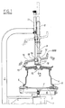
- Figures 1 to 3 show the base 1 of the tyre removal machine, from which there extends upwards in the usual manner a rotatable shaft 2 supporting the rotary platform 3 on which the wheel rim 4 is locked by usual self-centering jaws 5.
- jaws 5 are made to undergo approach and withdrawal in the usual manner by the cylinder-piston unit.
- a nosepiece or conical member 10 able to engage the central hole of the wheel rim 4.
- the nosepiece 10 is fixed to the rod 9 in such a manner as to be able to rotate about its axis.
- the vertical movements of the rod 9 are controlled by a cylinder-piston unit 11, the body of which is rigid with the column 7.
- the rod 9 In an intermediate position between the nosepiece 10 and the tube 8 the rod 9 carries a slidable member 12 provided with a seat 13 inclined to the horizontal plane.
- the seat 13 is prismatic and slidingly carries a prismatic arm 14, the axis of which is contained in a chordal plane of the wheel rim 4.
- the arm 14 is inclined such that its lower end is closer to the column 7, to said end there being fixed the tool 15 intended to operate on the tyre bead.
- Said tool 15 is of usual form and operates in the usual manner.
- the member 12 and rod 9 are locked together by a strangling plate 16 operated by a cylinder-piston unit 17.
- the plate 16 is positioned below the member 12 such that its tightening results in automatic raising of the member 12.
- the arm 14 and the member 12 are likewise locked together by a strangling plate 18 operated by a cylinder-piston unit 19.
- the strangling plate 18 is positioned on that side of the member 12 facing the column 7 so that when the strangling plate is tightened the tool 15 is automatically made to approach the column 7.
- the travel movements caused by tightening the strangling plates 16 and 18 are such as to withdraw the tool 15 a certain distance from the edge of the wheel rim 4 both vertically and horizontally.
- the structure comprising the column 7 and the rod 9 becomes sufficiently rigid as not to deform under the action of the forces transmitted by the tool 15 when it interferes with the tyre bead, hence ensuring the absence of undesirable contact between the tool 15 and the wheel rim 4.
- the reference numeral 888 indicates means for operating said strangling devices.
- Figures 4 to 6 show a second embodiment of the invention, suitable for application to already existing tyre removal machines.
- Said figures show the base 20 of a traditional tyre removal machine from which the rotary shaft 21 extends upwards to support the rotary platform 22.
- the wheel rim 23 is placed on the platform 22 and maintained locked and centered thereon by usual self-centering jaws 24 operated by the piston 25.
- the vertical column 26 which in the illustrated version can be inclined by rotation about the pivot 27, and is maintained in the vertical position by a catch 271.
- a tube 28 At the top of the column 26 there is positioned a tube 28 with its axis perpendicular to that of the column, and in which there slides a prismatic arm 29.
- the arm 29 is locked by a strangling plate 30, the operation of which automatically causes the arm 29 to travel towards the left in Figure 4.
- the rod 32 is locked to the tube 31 by a strangling device, not shown, which when tightened automatically causes the rod 32 to undergo a small upward movement.
- the usual tool 33 for interacting with the tyre bead is fixed to the lower end of the rod 32.
- the rod 32 carries a first slidable member 34 supporting a horizontal arm 35.
- the slidable member 34 is composed of two jaws 341 and 342 arranged to embrace the rod 32, so clamping it.
- the nut is positioned to the side of the horizontal arm 35, and is in contact with the jaw 342 by virtue of the spacer 347 which is integral with said nut.
- the arm 35 is welded to the jaw 342 and carries said slidable member 36 as stated.
- the member 36 comprises two mutually perpendicular clamping seats, of which one 355 accommodates the arm 35, and the other 38 accommodates a first pin 39.
- the axis of the conical member 37 can be located exactly in the vertical plane passing through the axis of the rod 32.
- the conical member 37 is clamped onto the arm 35, and the rod 39 onto the member 36, by a single bolt 41 which is inserted through a seat perpendicular to the axis of both said clamping seats, and is screwed into a nut 42 provided with an operating appendix 43.
- the operator manually brings the tool 33 into contact with the edge of the wheel rim 23, and then locks it in position by operating both the said strangling devices, which automatically results in separation from the wheel rim.
Landscapes
- Engineering & Computer Science (AREA)
- Mechanical Engineering (AREA)
- Testing Of Balance (AREA)
- Tires In General (AREA)
- Tyre Moulding (AREA)
- Automatic Assembly (AREA)
- Processing And Handling Of Plastics And Other Materials For Molding In General (AREA)
- Crushing And Pulverization Processes (AREA)
Claims (6)
- Machine pour le démontage de pneumatiques de jantes de roue et pour le montage de pneumatiques sur des jantes de roue, comprenant une embase (1 ; 20), une plate-forme (3 ; 22) tournant sur l'embase, et une colonne (7 ; 26) qui s'étend verticalement vers le haut à partir de l'embase sur le côté de la plate-forme et supporte, l'un derrière l'autre, deux éléments coulissant mutuellement dont l'un porte à son extrémité l'outil (15 ; 33) qui doit agir sur le talon du pneumatique, et des moyens qui sont susceptibles d'être fixés au centre de la jante de la roue, lesdits moyens susceptibles d'être fixés au centre de la jante de la roue comprenant un organe tronconique (10) coaxial à ladite plate-forme et qui est libre de toumer autour de son axe.
- Machine selon la revendication 1, caractérisée en ce que la colonne (7) s'étendant vers le haut à partir de l'embase (1) sur le côté de la plate-forme est recourbée à sa partie supérieure au-dessus de la plate-forme et comprend à son extrémité un siège de guidage et de coulissement (8) d'axe vertical, coaxial à la plate-forme sous-jacente rotative, pour recevoir une barre (9) à l'extrémité de laquelle est monté en coulissement un organe (12) qui loge de façon coulissante un bras (14), à l'extrémité duquel est fixé l'outil (15) pour venir en contact avec le talon du pneumatique.
- Machine selon la revendication 2, caractérisée en ce que ledit organe (12) comprend deux sièges de guidage sensiblement mutuellement perpendiculaires à l'intérieur desquels coulissent ladite barre et ledit bras, chaque siège étant associé à une plaque d'étranglement (16,18) actionnée par une unité pneumatique cylindre-piston (17,19), et qui lorsqu'elle est inclinée verrouille la barre ou le bras tout en provoquant simultanément l'action d'un mouvement de manière à écarter l'outil du bord de la jante de la roue.
- Machine selon la revendication 1, caractérisée en ce que la colonne (26) qui s'étend verticalement vers le haut sur le côté de la plate-forme (22) à sa partie supérieure comprend un tube (28) à axe sensiblement horizontal pour supporter et guider un bras coulissant comportant à son extrémité un tube (31) à axe sensiblement vertical pour supporter et guider une barre verticale (32) portant à son extrémité inférieure l'outil (33) qui doit venir en contact avec le talon du pneumatique, ladite barre portant un premier organe coulissant (34) supportant un bras horizontal (35), à l'extrémité duquel coulisse un second organe (36) portant un organe conique (37) destiné à être introduit et verrouillé dans le trou central de la jante de la roue.
- Machine selon la revendication 4, caractérisée en ce que ledit second organe comprend deux sièges mutuellement perpendiculaires pour supporter et guider respectivement le bras horizontal (35) et une première goupille verticale (39), laquelle est solidaire d'une seconde goupille verticale (40) qui est parallèle, mais n'est pas alignée avec elle, et à l'extrémité de laquelle est fixé l'organe tronconique (37).
- Machine selon la revendication 5, caractérisée en ce que lesdits deux sièges sont déformables élastiquement sous l'action d'un seul boulon (41,42) pouvant être actionné par un levier (43), pour verrouiller simultanément le bras horizontal et la première goupille verticale à l'intérieur desdits sièges, respectivement.
Applications Claiming Priority (2)
| Application Number | Priority Date | Filing Date | Title |
|---|---|---|---|
| IT96RE000028A IT1287640B1 (it) | 1996-05-03 | 1996-05-03 | Macchina per il montaggio e lo smontaggio dei pneumatici sui e dai rispettivi cerchioni |
| ITRE960028 | 1996-05-03 |
Publications (3)
| Publication Number | Publication Date |
|---|---|
| EP0805053A2 EP0805053A2 (fr) | 1997-11-05 |
| EP0805053A3 EP0805053A3 (fr) | 1998-04-15 |
| EP0805053B1 true EP0805053B1 (fr) | 2002-06-05 |
Family
ID=11398869
Family Applications (1)
| Application Number | Title | Priority Date | Filing Date |
|---|---|---|---|
| EP97200965A Expired - Lifetime EP0805053B1 (fr) | 1996-05-03 | 1997-04-02 | Machine pour le montage et le démontage de pneus des jantes de roues |
Country Status (6)
| Country | Link |
|---|---|
| US (1) | US5836368A (fr) |
| EP (1) | EP0805053B1 (fr) |
| AT (1) | ATE218450T1 (fr) |
| DE (1) | DE69712979T2 (fr) |
| ES (1) | ES2175259T3 (fr) |
| IT (1) | IT1287640B1 (fr) |
Cited By (1)
| Publication number | Priority date | Publication date | Assignee | Title |
|---|---|---|---|---|
| CN107323185A (zh) * | 2017-08-08 | 2017-11-07 | 鞍山强锋久盛科技发展有限公司 | 重型矿用汽车轮胎扒胎机 |
Families Citing this family (12)
| Publication number | Priority date | Publication date | Assignee | Title |
|---|---|---|---|---|
| IT1294900B1 (it) * | 1997-07-18 | 1999-04-23 | Gs Srl | Dispositivo per il bloccaggio di una ruota con pneumatico ad una piattaforma. |
| IT1297989B1 (it) * | 1997-10-24 | 1999-12-20 | Corghi Spa | Macchina smontagomme |
| IT1310170B1 (it) * | 1999-02-04 | 2002-02-11 | Giuliano Srl | Macchina per il montaggio e lo smontaggio di pneumatici di tipospeciale |
| IT248249Y1 (it) * | 1999-04-30 | 2002-12-16 | Elettromeccaniche S I C E Spa | Macchina smontagomme con torretta a posizionamento manuale oautomatico |
| US6247516B1 (en) | 2000-04-18 | 2001-06-19 | Rick Sinclair | Tire changing apparatus and method |
| US6401788B1 (en) * | 2001-06-29 | 2002-06-11 | Rick Sinclair | Tire changing apparatus and method |
| USD515891S1 (en) * | 2002-12-09 | 2006-02-28 | Cortez Frank L | Universal hub removal set |
| US7621311B2 (en) * | 2005-10-05 | 2009-11-24 | Android Industries Llc | Tire-wheel assembly adjuster |
| US7343955B2 (en) * | 2005-12-28 | 2008-03-18 | Hennessy Industries, Inc. | Tire changing machine |
| US7438109B2 (en) * | 2005-12-30 | 2008-10-21 | Hennessy Industries, Inc. | Tire changer |
| JP4940729B2 (ja) * | 2006-03-31 | 2012-05-30 | 株式会社ジェイテクト | 工作物の研削方法及び研削装置 |
| JP4230505B2 (ja) * | 2006-11-30 | 2009-02-25 | 株式会社アルティア | タイヤマウンタ及びタイヤのマウント方法 |
Family Cites Families (12)
| Publication number | Priority date | Publication date | Assignee | Title |
|---|---|---|---|---|
| US2850061A (en) * | 1955-02-25 | 1958-09-02 | Harry G Twiford | Center post for tire changer |
| BE562929A (fr) * | 1957-12-04 | |||
| US3139137A (en) * | 1961-12-28 | 1964-06-30 | Alfred A Wiles | Tire mounting and demounting apparatus |
| BE764970A (fr) * | 1971-03-30 | 1971-08-16 | Duquesne Victor | Dispositif pour le montage et le demontage des pneus equipant les rouesdes vehicules automobiles. |
| GB1431962A (en) * | 1973-09-04 | 1976-04-14 | Adams J W | Stand for motorcycle wheels |
| US4830079A (en) * | 1982-12-30 | 1989-05-16 | Toyota Jidosha Kabushiki Kaisha | Method and apparatus for mounting tires on wheels |
| DE3401476A1 (de) * | 1984-01-18 | 1985-07-25 | Gebr. Hofmann Gmbh & Co Kg Maschinenfabrik, 6100 Darmstadt | Montagevorrichtung fuer reifen |
| US4811774A (en) * | 1987-02-02 | 1989-03-14 | Fmc Corporation | Tire Changer safety arm |
| US4765387A (en) * | 1987-02-02 | 1988-08-23 | Fmc Corporation | Tire changer safety foot |
| US4884611A (en) * | 1988-10-24 | 1989-12-05 | Schmidt Raymond H | Tire changing machine |
| JP2564057B2 (ja) * | 1991-08-27 | 1996-12-18 | 株式会社ブリヂストン | タイヤのリム組み内圧充てん方法およびその装置 |
| TW343179B (en) * | 1995-10-02 | 1998-10-21 | Maciss R L | Burst protection device for tire removing machines a burst protection device for tire removing machines of the type having a platform on which a wheel can be located and an arm supporting a bead extractor. |
-
1996
- 1996-05-03 IT IT96RE000028A patent/IT1287640B1/it active IP Right Grant
-
1997
- 1997-04-02 AT AT97200965T patent/ATE218450T1/de not_active IP Right Cessation
- 1997-04-02 EP EP97200965A patent/EP0805053B1/fr not_active Expired - Lifetime
- 1997-04-02 DE DE69712979T patent/DE69712979T2/de not_active Expired - Fee Related
- 1997-04-02 ES ES97200965T patent/ES2175259T3/es not_active Expired - Lifetime
- 1997-04-16 US US08/842,788 patent/US5836368A/en not_active Expired - Fee Related
Cited By (1)
| Publication number | Priority date | Publication date | Assignee | Title |
|---|---|---|---|---|
| CN107323185A (zh) * | 2017-08-08 | 2017-11-07 | 鞍山强锋久盛科技发展有限公司 | 重型矿用汽车轮胎扒胎机 |
Also Published As
| Publication number | Publication date |
|---|---|
| ES2175259T3 (es) | 2002-11-16 |
| ATE218450T1 (de) | 2002-06-15 |
| EP0805053A2 (fr) | 1997-11-05 |
| US5836368A (en) | 1998-11-17 |
| DE69712979T2 (de) | 2002-09-19 |
| EP0805053A3 (fr) | 1998-04-15 |
| IT1287640B1 (it) | 1998-08-06 |
| ITRE960028A1 (it) | 1997-11-03 |
| ITRE960028A0 (it) | 1996-05-03 |
| DE69712979D1 (de) | 2002-07-11 |
Similar Documents
| Publication | Publication Date | Title |
|---|---|---|
| EP0805053B1 (fr) | Machine pour le montage et le démontage de pneus des jantes de roues | |
| US6056034A (en) | Difficult to mount tire changer and method for handling thereof | |
| US6527032B2 (en) | Automatic bead release device for tire removal machines, and tire removal machines equipped therewith | |
| US6619362B2 (en) | Automatic tyre removal and mounting device and tyre removal machines equipped therewith | |
| US8291958B2 (en) | Machine for fitting and removing the tires of vehicles | |
| EP0947360B1 (fr) | Machine pour le démontage de pneus et accessoires pour celle-çi | |
| US9168797B2 (en) | Tyre demounting machine | |
| EP1897709B1 (fr) | Machine de fixation et de retrait de pneumatiques de véhicules | |
| EP2125394B1 (fr) | Appareil destiné à des machines de changement de pneu | |
| EP2253487B1 (fr) | Outil pour un appareil de changement de pneus | |
| US4765387A (en) | Tire changer safety foot | |
| EP0512595B1 (fr) | Briseur de talons des pneus avec multiple adaptabilité | |
| US6145566A (en) | Center post tire changing apparatus | |
| CA1232531A (fr) | Demonte-pneu pour roues en alliage leger | |
| EP2269841B1 (fr) | Bras détacheur de talon, procédé de démontage de pneu et appareil utilisant le bras détacheur de talon | |
| US7946016B2 (en) | Method and machine for removing a tyre fitted with a rigid inner run-flat ring | |
| US4840215A (en) | Tire changer safety post | |
| US20230123205A1 (en) | Machine for mounting and demounting a tyre relative to a corresponding rim and wheel servicing method | |
| EP0659597B1 (fr) | Dispositif pour faciliter le démontage et le montage de pneu d'une jante de roue, pour machines à démonter les pneux en général | |
| US5458177A (en) | Machine for mounting tires on wheel rims | |
| EP1314583B1 (fr) | Dispositif pour l'insertion et l'extraction d'un anneau de support dans un pneumatique | |
| JP3704370B2 (ja) | ホイールリムからタイヤビードを外すための、タイヤ取外し機械用ビード解放ユニツト | |
| US3866655A (en) | Tire changer with improved tire changing tool | |
| GB2034258A (en) | Tyre Bead Dislodging Device |
Legal Events
| Date | Code | Title | Description |
|---|---|---|---|
| PUAI | Public reference made under article 153(3) epc to a published international application that has entered the european phase |
Free format text: ORIGINAL CODE: 0009012 |
|
| AK | Designated contracting states |
Kind code of ref document: A2 Designated state(s): AT BE CH DE ES FR GB IT LI PT SE |
|
| PUAL | Search report despatched |
Free format text: ORIGINAL CODE: 0009013 |
|
| RHK1 | Main classification (correction) |
Ipc: B60C 25/138 |
|
| AK | Designated contracting states |
Kind code of ref document: A3 Designated state(s): AT BE CH DE ES FR GB IT LI PT SE |
|
| 17P | Request for examination filed |
Effective date: 19980703 |
|
| 17Q | First examination report despatched |
Effective date: 19991213 |
|
| RAP1 | Party data changed (applicant data changed or rights of an application transferred) |
Owner name: CORGHI S.P.A. |
|
| GRAG | Despatch of communication of intention to grant |
Free format text: ORIGINAL CODE: EPIDOS AGRA |
|
| GRAG | Despatch of communication of intention to grant |
Free format text: ORIGINAL CODE: EPIDOS AGRA |
|
| GRAH | Despatch of communication of intention to grant a patent |
Free format text: ORIGINAL CODE: EPIDOS IGRA |
|
| GRAH | Despatch of communication of intention to grant a patent |
Free format text: ORIGINAL CODE: EPIDOS IGRA |
|
| GRAA | (expected) grant |
Free format text: ORIGINAL CODE: 0009210 |
|
| AK | Designated contracting states |
Kind code of ref document: B1 Designated state(s): AT BE CH DE ES FR GB IT LI PT SE |
|
| PG25 | Lapsed in a contracting state [announced via postgrant information from national office to epo] |
Ref country code: LI Free format text: LAPSE BECAUSE OF FAILURE TO SUBMIT A TRANSLATION OF THE DESCRIPTION OR TO PAY THE FEE WITHIN THE PRESCRIBED TIME-LIMIT Effective date: 20020605 Ref country code: CH Free format text: LAPSE BECAUSE OF FAILURE TO SUBMIT A TRANSLATION OF THE DESCRIPTION OR TO PAY THE FEE WITHIN THE PRESCRIBED TIME-LIMIT Effective date: 20020605 Ref country code: BE Free format text: LAPSE BECAUSE OF FAILURE TO SUBMIT A TRANSLATION OF THE DESCRIPTION OR TO PAY THE FEE WITHIN THE PRESCRIBED TIME-LIMIT Effective date: 20020605 Ref country code: AT Free format text: LAPSE BECAUSE OF FAILURE TO SUBMIT A TRANSLATION OF THE DESCRIPTION OR TO PAY THE FEE WITHIN THE PRESCRIBED TIME-LIMIT Effective date: 20020605 |
|
| REF | Corresponds to: |
Ref document number: 218450 Country of ref document: AT Date of ref document: 20020615 Kind code of ref document: T |
|
| REG | Reference to a national code |
Ref country code: GB Ref legal event code: FG4D |
|
| REG | Reference to a national code |
Ref country code: CH Ref legal event code: EP |
|
| REF | Corresponds to: |
Ref document number: 69712979 Country of ref document: DE Date of ref document: 20020711 |
|
| ET | Fr: translation filed | ||
| PG25 | Lapsed in a contracting state [announced via postgrant information from national office to epo] |
Ref country code: SE Free format text: LAPSE BECAUSE OF FAILURE TO SUBMIT A TRANSLATION OF THE DESCRIPTION OR TO PAY THE FEE WITHIN THE PRESCRIBED TIME-LIMIT Effective date: 20020905 Ref country code: PT Free format text: LAPSE BECAUSE OF FAILURE TO SUBMIT A TRANSLATION OF THE DESCRIPTION OR TO PAY THE FEE WITHIN THE PRESCRIBED TIME-LIMIT Effective date: 20020905 |
|
| REG | Reference to a national code |
Ref country code: ES Ref legal event code: FG2A Ref document number: 2175259 Country of ref document: ES Kind code of ref document: T3 |
|
| REG | Reference to a national code |
Ref country code: CH Ref legal event code: PL |
|
| PG25 | Lapsed in a contracting state [announced via postgrant information from national office to epo] |
Ref country code: GB Free format text: LAPSE BECAUSE OF NON-PAYMENT OF DUE FEES Effective date: 20030402 |
|
| PLBE | No opposition filed within time limit |
Free format text: ORIGINAL CODE: 0009261 |
|
| STAA | Information on the status of an ep patent application or granted ep patent |
Free format text: STATUS: NO OPPOSITION FILED WITHIN TIME LIMIT |
|
| 26N | No opposition filed |
Effective date: 20030306 |
|
| GBPC | Gb: european patent ceased through non-payment of renewal fee |
Effective date: 20030402 |
|
| PGFP | Annual fee paid to national office [announced via postgrant information from national office to epo] |
Ref country code: ES Payment date: 20040225 Year of fee payment: 8 |
|
| PGFP | Annual fee paid to national office [announced via postgrant information from national office to epo] |
Ref country code: FR Payment date: 20040408 Year of fee payment: 8 |
|
| PGFP | Annual fee paid to national office [announced via postgrant information from national office to epo] |
Ref country code: DE Payment date: 20040417 Year of fee payment: 8 |
|
| PG25 | Lapsed in a contracting state [announced via postgrant information from national office to epo] |
Ref country code: ES Free format text: LAPSE BECAUSE OF NON-PAYMENT OF DUE FEES Effective date: 20050404 |
|
| PG25 | Lapsed in a contracting state [announced via postgrant information from national office to epo] |
Ref country code: DE Free format text: LAPSE BECAUSE OF NON-PAYMENT OF DUE FEES Effective date: 20051101 |
|
| PG25 | Lapsed in a contracting state [announced via postgrant information from national office to epo] |
Ref country code: FR Free format text: LAPSE BECAUSE OF NON-PAYMENT OF DUE FEES Effective date: 20051230 |
|
| REG | Reference to a national code |
Ref country code: FR Ref legal event code: ST Effective date: 20051230 |
|
| REG | Reference to a national code |
Ref country code: ES Ref legal event code: FD2A Effective date: 20050404 |
|
| PGFP | Annual fee paid to national office [announced via postgrant information from national office to epo] |
Ref country code: IT Payment date: 20070522 Year of fee payment: 11 |
|
| PG25 | Lapsed in a contracting state [announced via postgrant information from national office to epo] |
Ref country code: IT Free format text: LAPSE BECAUSE OF NON-PAYMENT OF DUE FEES Effective date: 20080402 |