EP0805053B1 - Maschine für das Montieren und Demontieren von Reifen auf und von Radfelgen - Google Patents
Maschine für das Montieren und Demontieren von Reifen auf und von Radfelgen Download PDFInfo
- Publication number
- EP0805053B1 EP0805053B1 EP97200965A EP97200965A EP0805053B1 EP 0805053 B1 EP0805053 B1 EP 0805053B1 EP 97200965 A EP97200965 A EP 97200965A EP 97200965 A EP97200965 A EP 97200965A EP 0805053 B1 EP0805053 B1 EP 0805053B1
- Authority
- EP
- European Patent Office
- Prior art keywords
- platform
- tool
- machine
- arm
- rod
- Prior art date
- Legal status (The legal status is an assumption and is not a legal conclusion. Google has not performed a legal analysis and makes no representation as to the accuracy of the status listed.)
- Expired - Lifetime
Links
- 239000011324 bead Substances 0.000 claims abstract description 9
- 229910001234 light alloy Inorganic materials 0.000 description 2
- 230000000284 resting effect Effects 0.000 description 2
- 238000000926 separation method Methods 0.000 description 1
- 125000006850 spacer group Chemical group 0.000 description 1
Images


Classifications
-
- B—PERFORMING OPERATIONS; TRANSPORTING
- B60—VEHICLES IN GENERAL
- B60C—VEHICLE TYRES; TYRE INFLATION; TYRE CHANGING; CONNECTING VALVES TO INFLATABLE ELASTIC BODIES IN GENERAL; DEVICES OR ARRANGEMENTS RELATED TO TYRES
- B60C25/00—Apparatus or tools adapted for mounting, removing or inspecting tyres
- B60C25/01—Apparatus or tools adapted for mounting, removing or inspecting tyres for removing tyres from or mounting tyres on wheels
- B60C25/05—Machines
- B60C25/053—Support of wheel parts during machine operation
- B60C25/0545—Support of wheel parts during machine operation with rotary motion of tool or tyre support, e.g. turntables
-
- B—PERFORMING OPERATIONS; TRANSPORTING
- B60—VEHICLES IN GENERAL
- B60C—VEHICLE TYRES; TYRE INFLATION; TYRE CHANGING; CONNECTING VALVES TO INFLATABLE ELASTIC BODIES IN GENERAL; DEVICES OR ARRANGEMENTS RELATED TO TYRES
- B60C25/00—Apparatus or tools adapted for mounting, removing or inspecting tyres
- B60C25/01—Apparatus or tools adapted for mounting, removing or inspecting tyres for removing tyres from or mounting tyres on wheels
- B60C25/05—Machines
- B60C25/132—Machines for removing and mounting tyres
Definitions
- Machines for mounting tyres onto respective wheel rims and for performing the opposite operation comprising essentially a rotary platform of vertical axis provided with self-centering means for locking the wheel rim, which is overlaid by a support supporting, in a manner adjustable both in height and in horizontal direction, a tool arranged to interact with the edge, or bead, of the tyre in order to urge it below, or extract it from, the edge of the wheel rim.
- said tool is positioned at the end of a vertical support rod which slides within the end seat of a horizontal arm, to which the tool can be locked in height.
- the horizontal arm slides within the end seat of a vertical column which extends upwards from the machine base to the side of the platform which receives the tyre.
- Said horizontal arm is provided with means for locking it in the desired position.
- EP 0767098 falling under the provisions of Article 54(3)EPC and therefore being only relevant to the question of novelty, discloses a machine of the above mentioned type, further comprising a burst protection device consisting of a wheel locking member.
- the wheel locking member comprises a vertical rod slidably mounted at the end of the horizontal supporting arm of the mounting-demounting tool.
- a stationary presser of conical shape is mounted, suitable for resting on the centre hole of the wheel.
- the stationary presser may be used only while the inflation of the tyre does occur and the wheel is stationary, and must be set aside while the wheel rotates to be subjected to the tyre mounting-demounting operation.
- Said configuration presents stability problems, which are particularly serious if operating on light alloy wheel rims.
- the tool is positioned at the end of a series of elements of substantial length which, if the tool is subjected to considerable stresses induced by its action on the tyre bead, are deformed to the extent of causing the tool to slip against the wheel rim.
- the object of the present invention is to provide a tool support structure in tyre mounting and removal machines which overcomes the aforesaid drawbacks.
- a tool support structure which is secured, at least at one point, to the centre of the wheel rim under operation.
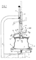
- Figures 1 to 3 show the base 1 of the tyre removal machine, from which there extends upwards in the usual manner a rotatable shaft 2 supporting the rotary platform 3 on which the wheel rim 4 is locked by usual self-centering jaws 5.
- jaws 5 are made to undergo approach and withdrawal in the usual manner by the cylinder-piston unit.
- a nosepiece or conical member 10 able to engage the central hole of the wheel rim 4.
- the nosepiece 10 is fixed to the rod 9 in such a manner as to be able to rotate about its axis.
- the vertical movements of the rod 9 are controlled by a cylinder-piston unit 11, the body of which is rigid with the column 7.
- the rod 9 In an intermediate position between the nosepiece 10 and the tube 8 the rod 9 carries a slidable member 12 provided with a seat 13 inclined to the horizontal plane.
- the seat 13 is prismatic and slidingly carries a prismatic arm 14, the axis of which is contained in a chordal plane of the wheel rim 4.
- the arm 14 is inclined such that its lower end is closer to the column 7, to said end there being fixed the tool 15 intended to operate on the tyre bead.
- Said tool 15 is of usual form and operates in the usual manner.
- the member 12 and rod 9 are locked together by a strangling plate 16 operated by a cylinder-piston unit 17.
- the plate 16 is positioned below the member 12 such that its tightening results in automatic raising of the member 12.
- the arm 14 and the member 12 are likewise locked together by a strangling plate 18 operated by a cylinder-piston unit 19.
- the strangling plate 18 is positioned on that side of the member 12 facing the column 7 so that when the strangling plate is tightened the tool 15 is automatically made to approach the column 7.
- the travel movements caused by tightening the strangling plates 16 and 18 are such as to withdraw the tool 15 a certain distance from the edge of the wheel rim 4 both vertically and horizontally.
- the structure comprising the column 7 and the rod 9 becomes sufficiently rigid as not to deform under the action of the forces transmitted by the tool 15 when it interferes with the tyre bead, hence ensuring the absence of undesirable contact between the tool 15 and the wheel rim 4.
- the reference numeral 888 indicates means for operating said strangling devices.
- Figures 4 to 6 show a second embodiment of the invention, suitable for application to already existing tyre removal machines.
- Said figures show the base 20 of a traditional tyre removal machine from which the rotary shaft 21 extends upwards to support the rotary platform 22.
- the wheel rim 23 is placed on the platform 22 and maintained locked and centered thereon by usual self-centering jaws 24 operated by the piston 25.
- the vertical column 26 which in the illustrated version can be inclined by rotation about the pivot 27, and is maintained in the vertical position by a catch 271.
- a tube 28 At the top of the column 26 there is positioned a tube 28 with its axis perpendicular to that of the column, and in which there slides a prismatic arm 29.
- the arm 29 is locked by a strangling plate 30, the operation of which automatically causes the arm 29 to travel towards the left in Figure 4.
- the rod 32 is locked to the tube 31 by a strangling device, not shown, which when tightened automatically causes the rod 32 to undergo a small upward movement.
- the usual tool 33 for interacting with the tyre bead is fixed to the lower end of the rod 32.
- the rod 32 carries a first slidable member 34 supporting a horizontal arm 35.
- the slidable member 34 is composed of two jaws 341 and 342 arranged to embrace the rod 32, so clamping it.
- the nut is positioned to the side of the horizontal arm 35, and is in contact with the jaw 342 by virtue of the spacer 347 which is integral with said nut.
- the arm 35 is welded to the jaw 342 and carries said slidable member 36 as stated.
- the member 36 comprises two mutually perpendicular clamping seats, of which one 355 accommodates the arm 35, and the other 38 accommodates a first pin 39.
- the axis of the conical member 37 can be located exactly in the vertical plane passing through the axis of the rod 32.
- the conical member 37 is clamped onto the arm 35, and the rod 39 onto the member 36, by a single bolt 41 which is inserted through a seat perpendicular to the axis of both said clamping seats, and is screwed into a nut 42 provided with an operating appendix 43.
- the operator manually brings the tool 33 into contact with the edge of the wheel rim 23, and then locks it in position by operating both the said strangling devices, which automatically results in separation from the wheel rim.
Landscapes
- Engineering & Computer Science (AREA)
- Mechanical Engineering (AREA)
- Testing Of Balance (AREA)
- Tires In General (AREA)
- Tyre Moulding (AREA)
- Automatic Assembly (AREA)
- Processing And Handling Of Plastics And Other Materials For Molding In General (AREA)
- Crushing And Pulverization Processes (AREA)
Claims (6)
- Maschine für das Demontieren und Montieren von Reifen von und auf Radfelgen, die eine Basis (1; 20), eine sich auf der Basis drehende Plattform (3;22) und eine Säule (7;26) aufweist, die sich von der Basis auf der Seite der Plattform vertikal nach oben erstreckt und nacheinander zwei gegeneinander gleitend bewegbare Elemente aufweist, wovon eines an seinem Ende das Werkzeug (15;33) trägt, das auf den Reifenwulst einwirken soll, und ein Mittel, das zur Befestigung im Mittelpunkt der Radfelge geeignet ist, wobei das Mittel, das zur Befestigung im Mittelpunkt der Radfelge geeignet ist, ein kegelstumpfförmiges Teil (10) aufweist, das koaxial zu der Plattform verläuft und sich frei um seine Achse drehen kann.
- Maschine nach Anspruch 1,
dadurch gekennzeichnet, daß
die Säule (7), die sich von der Basis (1) auf der Seite der Plattform vertikal nach oben erstreckt, oben über der Plattform gekrümmt ist und an ihrem Ende einen koaxial zu der darunterliegenden drehbaren Plattform verlaufenden Gleit- und Führungssitz (8) mit vertikaler Achse zur Aufnahme einer Stange (9) aufweist, an deren Ende ein Teil (12) gleitend bewegbar angebracht ist, das einen Arm (14) gleitend bewegbar aufnimmt, an dessen Ende das Werkzeug (15), das mit dem Reifenwulst in Kontakt kommen soll, befestigt ist. - Maschine nach Anspruch 2,
dadurch gekennzeichnet, daß
das Teil (12) zwei im wesentlichen zueinander senkrechte Führungssitze aufweist, innerhalb derer die Stange und der Arm gleiten, wobei jeder Sitz mit einer von einer pneumatischen Zylinder-Kolben-Einheit (17,19) betätigten Drosselungsplatte (16, 18) verbunden ist, die dann, wenn sie geneigt ist, die Stange oder den Arm arretiert, wobei sie diesen gleichzeitig zur Ausführung einer Bewegung dahingehend veranlaßt, daß er das Werkzeug von der Radfelgenkante beabstandet. - Maschine nach Anspruch 1,
dadurch gekennzeichnet, daß
die Säule (26), die sich von der Basis auf der Seite der Plattform (22) vertikal nach oben erstreckt, oben ein Rohr (28) mit einer im wesentlichen horizontalen Achse zum Tragen und Führen eines gleitend bewegbaren Armes aufweist, der an seinem Ende mit einem Rohr (31) mit einer im wesentlichen vertikalen Achse zum Tragen und Führen einer vertikalen Stange (32) versehen ist, die an ihrem unteren Ende das Werkzeug (33) trägt, das mit dem Reifenwulst in Kontakt kommen soll, wobei die Stange ein erstes gleitend bewegbares Teil (34) trägt, das einen horizontalen Arm (35) trägt, an dessen Ende ein zweites Teil (36) gleitet, das ein konisches Teil (37) zum Einsetzen und Arretieren in dem mittigen Loch in der Radfelge trägt. - Maschine nach Anspruch 4,
dadurch gekennzeichnet, daß
das zweite Teil zwei zueinander senkrechte Sitze jeweils zum Tragen und Führen des horizontalen Armes (35) und eines ersten vertikalen Stiftes (39) aufweist, der starr mit einem zweiten vertikalen Stift (40) verbunden ist, der parallel zu demselben verläuft, jedoch nicht auf diesen ausgerichtet ist, und an dessen Ende das kegelstumpfförmige Teil (37) befestigt ist. - Maschine nach Anspruch 5,
dadurch gekennzeichnet, daß
die zwei Sitze durch die Einwirkung eines durch einen Hebel (43) betätigbaren Einzelbolzen (41,42) elastisch verformbar sind, um gleichzeitig jeweils den horizontalen Arm und den ersten vertikalen Stift innerhalb der Sitze zu arretieren.
Applications Claiming Priority (2)
| Application Number | Priority Date | Filing Date | Title |
|---|---|---|---|
| ITRE960028 | 1996-05-03 | ||
| IT96RE000028A IT1287640B1 (it) | 1996-05-03 | 1996-05-03 | Macchina per il montaggio e lo smontaggio dei pneumatici sui e dai rispettivi cerchioni |
Publications (3)
| Publication Number | Publication Date |
|---|---|
| EP0805053A2 EP0805053A2 (de) | 1997-11-05 |
| EP0805053A3 EP0805053A3 (de) | 1998-04-15 |
| EP0805053B1 true EP0805053B1 (de) | 2002-06-05 |
Family
ID=11398869
Family Applications (1)
| Application Number | Title | Priority Date | Filing Date |
|---|---|---|---|
| EP97200965A Expired - Lifetime EP0805053B1 (de) | 1996-05-03 | 1997-04-02 | Maschine für das Montieren und Demontieren von Reifen auf und von Radfelgen |
Country Status (6)
| Country | Link |
|---|---|
| US (1) | US5836368A (de) |
| EP (1) | EP0805053B1 (de) |
| AT (1) | ATE218450T1 (de) |
| DE (1) | DE69712979T2 (de) |
| ES (1) | ES2175259T3 (de) |
| IT (1) | IT1287640B1 (de) |
Cited By (1)
| Publication number | Priority date | Publication date | Assignee | Title |
|---|---|---|---|---|
| CN107323185A (zh) * | 2017-08-08 | 2017-11-07 | 鞍山强锋久盛科技发展有限公司 | 重型矿用汽车轮胎扒胎机 |
Families Citing this family (12)
| Publication number | Priority date | Publication date | Assignee | Title |
|---|---|---|---|---|
| IT1294900B1 (it) * | 1997-07-18 | 1999-04-23 | Gs Srl | Dispositivo per il bloccaggio di una ruota con pneumatico ad una piattaforma. |
| IT1297989B1 (it) * | 1997-10-24 | 1999-12-20 | Corghi Spa | Macchina smontagomme |
| IT1310170B1 (it) * | 1999-02-04 | 2002-02-11 | Giuliano Srl | Macchina per il montaggio e lo smontaggio di pneumatici di tipospeciale |
| IT248249Y1 (it) * | 1999-04-30 | 2002-12-16 | Elettromeccaniche S I C E Spa | Macchina smontagomme con torretta a posizionamento manuale oautomatico |
| US6247516B1 (en) | 2000-04-18 | 2001-06-19 | Rick Sinclair | Tire changing apparatus and method |
| US6401788B1 (en) * | 2001-06-29 | 2002-06-11 | Rick Sinclair | Tire changing apparatus and method |
| USD515891S1 (en) * | 2002-12-09 | 2006-02-28 | Cortez Frank L | Universal hub removal set |
| US7621311B2 (en) * | 2005-10-05 | 2009-11-24 | Android Industries Llc | Tire-wheel assembly adjuster |
| US7343955B2 (en) * | 2005-12-28 | 2008-03-18 | Hennessy Industries, Inc. | Tire changing machine |
| US7438109B2 (en) * | 2005-12-30 | 2008-10-21 | Hennessy Industries, Inc. | Tire changer |
| JP4940729B2 (ja) * | 2006-03-31 | 2012-05-30 | 株式会社ジェイテクト | 工作物の研削方法及び研削装置 |
| JP4230505B2 (ja) * | 2006-11-30 | 2009-02-25 | 株式会社アルティア | タイヤマウンタ及びタイヤのマウント方法 |
Family Cites Families (12)
| Publication number | Priority date | Publication date | Assignee | Title |
|---|---|---|---|---|
| US2850061A (en) * | 1955-02-25 | 1958-09-02 | Harry G Twiford | Center post for tire changer |
| BE562929A (de) * | 1957-12-04 | |||
| US3139137A (en) * | 1961-12-28 | 1964-06-30 | Alfred A Wiles | Tire mounting and demounting apparatus |
| BE764970A (fr) * | 1971-03-30 | 1971-08-16 | Duquesne Victor | Dispositif pour le montage et le demontage des pneus equipant les rouesdes vehicules automobiles. |
| GB1431962A (en) * | 1973-09-04 | 1976-04-14 | Adams J W | Stand for motorcycle wheels |
| US4830079A (en) * | 1982-12-30 | 1989-05-16 | Toyota Jidosha Kabushiki Kaisha | Method and apparatus for mounting tires on wheels |
| DE3401476A1 (de) * | 1984-01-18 | 1985-07-25 | Gebr. Hofmann Gmbh & Co Kg Maschinenfabrik, 6100 Darmstadt | Montagevorrichtung fuer reifen |
| US4765387A (en) * | 1987-02-02 | 1988-08-23 | Fmc Corporation | Tire changer safety foot |
| US4811774A (en) * | 1987-02-02 | 1989-03-14 | Fmc Corporation | Tire Changer safety arm |
| US4884611A (en) * | 1988-10-24 | 1989-12-05 | Schmidt Raymond H | Tire changing machine |
| JP2564057B2 (ja) * | 1991-08-27 | 1996-12-18 | 株式会社ブリヂストン | タイヤのリム組み内圧充てん方法およびその装置 |
| TW343179B (en) * | 1995-10-02 | 1998-10-21 | Maciss R L | Burst protection device for tire removing machines a burst protection device for tire removing machines of the type having a platform on which a wheel can be located and an arm supporting a bead extractor. |
-
1996
- 1996-05-03 IT IT96RE000028A patent/IT1287640B1/it active IP Right Grant
-
1997
- 1997-04-02 EP EP97200965A patent/EP0805053B1/de not_active Expired - Lifetime
- 1997-04-02 ES ES97200965T patent/ES2175259T3/es not_active Expired - Lifetime
- 1997-04-02 AT AT97200965T patent/ATE218450T1/de not_active IP Right Cessation
- 1997-04-02 DE DE69712979T patent/DE69712979T2/de not_active Expired - Fee Related
- 1997-04-16 US US08/842,788 patent/US5836368A/en not_active Expired - Fee Related
Cited By (1)
| Publication number | Priority date | Publication date | Assignee | Title |
|---|---|---|---|---|
| CN107323185A (zh) * | 2017-08-08 | 2017-11-07 | 鞍山强锋久盛科技发展有限公司 | 重型矿用汽车轮胎扒胎机 |
Also Published As
| Publication number | Publication date |
|---|---|
| DE69712979T2 (de) | 2002-09-19 |
| EP0805053A3 (de) | 1998-04-15 |
| ES2175259T3 (es) | 2002-11-16 |
| ATE218450T1 (de) | 2002-06-15 |
| ITRE960028A0 (it) | 1996-05-03 |
| IT1287640B1 (it) | 1998-08-06 |
| ITRE960028A1 (it) | 1997-11-03 |
| EP0805053A2 (de) | 1997-11-05 |
| US5836368A (en) | 1998-11-17 |
| DE69712979D1 (de) | 2002-07-11 |
Similar Documents
| Publication | Publication Date | Title |
|---|---|---|
| EP0805053B1 (de) | Maschine für das Montieren und Demontieren von Reifen auf und von Radfelgen | |
| US6056034A (en) | Difficult to mount tire changer and method for handling thereof | |
| US6527032B2 (en) | Automatic bead release device for tire removal machines, and tire removal machines equipped therewith | |
| US6619362B2 (en) | Automatic tyre removal and mounting device and tyre removal machines equipped therewith | |
| US8291958B2 (en) | Machine for fitting and removing the tires of vehicles | |
| EP0947360B1 (de) | Reifendemontiervorrichtung und Zubehör | |
| EP2629992B1 (de) | Reifendemontiermaschine | |
| EP2125394B1 (de) | Vorrichtung für reifenwechselmaschinen | |
| EP1897709A1 (de) | Maschine zum Anbringen und Abnehmen von Fahrzeugreifen | |
| EP2253487B1 (de) | Werkzeug für eine Reifenabziehmaschine | |
| US4765387A (en) | Tire changer safety foot | |
| EP0512595B1 (de) | Anpassungsfähige Reifenabdrückvorrichtung | |
| EP2995478A2 (de) | Maschine zum abnehmen und anbringen von radreifen für fahrzeuge | |
| US6145566A (en) | Center post tire changing apparatus | |
| CA1232531A (en) | Tire changer accessory for use with custom alloy rims | |
| EP2269841B1 (de) | Wulstabdrückarm, Reifendemontageverfahren und -gerät, das einen Wulstabdrückarm benutzt | |
| US7946016B2 (en) | Method and machine for removing a tyre fitted with a rigid inner run-flat ring | |
| US4840215A (en) | Tire changer safety post | |
| US20230123205A1 (en) | Machine for mounting and demounting a tyre relative to a corresponding rim and wheel servicing method | |
| EP0659597B1 (de) | Vorrichtung zur Erleichterung des Demontierens und Montierens von Reifen auf und von Radfelgen | |
| US5458177A (en) | Machine for mounting tires on wheel rims | |
| EP1314583B1 (de) | Einrichtung zum Einschieben und Herausziehen von einem Stützring in einem Reifen | |
| JP3704370B2 (ja) | ホイールリムからタイヤビードを外すための、タイヤ取外し機械用ビード解放ユニツト | |
| CN112848794B (zh) | 用于夹紧车轮的轮辋的装置 |
Legal Events
| Date | Code | Title | Description |
|---|---|---|---|
| PUAI | Public reference made under article 153(3) epc to a published international application that has entered the european phase |
Free format text: ORIGINAL CODE: 0009012 |
|
| AK | Designated contracting states |
Kind code of ref document: A2 Designated state(s): AT BE CH DE ES FR GB IT LI PT SE |
|
| PUAL | Search report despatched |
Free format text: ORIGINAL CODE: 0009013 |
|
| RHK1 | Main classification (correction) |
Ipc: B60C 25/138 |
|
| AK | Designated contracting states |
Kind code of ref document: A3 Designated state(s): AT BE CH DE ES FR GB IT LI PT SE |
|
| 17P | Request for examination filed |
Effective date: 19980703 |
|
| 17Q | First examination report despatched |
Effective date: 19991213 |
|
| RAP1 | Party data changed (applicant data changed or rights of an application transferred) |
Owner name: CORGHI S.P.A. |
|
| GRAG | Despatch of communication of intention to grant |
Free format text: ORIGINAL CODE: EPIDOS AGRA |
|
| GRAG | Despatch of communication of intention to grant |
Free format text: ORIGINAL CODE: EPIDOS AGRA |
|
| GRAH | Despatch of communication of intention to grant a patent |
Free format text: ORIGINAL CODE: EPIDOS IGRA |
|
| GRAH | Despatch of communication of intention to grant a patent |
Free format text: ORIGINAL CODE: EPIDOS IGRA |
|
| GRAA | (expected) grant |
Free format text: ORIGINAL CODE: 0009210 |
|
| AK | Designated contracting states |
Kind code of ref document: B1 Designated state(s): AT BE CH DE ES FR GB IT LI PT SE |
|
| PG25 | Lapsed in a contracting state [announced via postgrant information from national office to epo] |
Ref country code: LI Free format text: LAPSE BECAUSE OF FAILURE TO SUBMIT A TRANSLATION OF THE DESCRIPTION OR TO PAY THE FEE WITHIN THE PRESCRIBED TIME-LIMIT Effective date: 20020605 Ref country code: CH Free format text: LAPSE BECAUSE OF FAILURE TO SUBMIT A TRANSLATION OF THE DESCRIPTION OR TO PAY THE FEE WITHIN THE PRESCRIBED TIME-LIMIT Effective date: 20020605 Ref country code: BE Free format text: LAPSE BECAUSE OF FAILURE TO SUBMIT A TRANSLATION OF THE DESCRIPTION OR TO PAY THE FEE WITHIN THE PRESCRIBED TIME-LIMIT Effective date: 20020605 Ref country code: AT Free format text: LAPSE BECAUSE OF FAILURE TO SUBMIT A TRANSLATION OF THE DESCRIPTION OR TO PAY THE FEE WITHIN THE PRESCRIBED TIME-LIMIT Effective date: 20020605 |
|
| REF | Corresponds to: |
Ref document number: 218450 Country of ref document: AT Date of ref document: 20020615 Kind code of ref document: T |
|
| REG | Reference to a national code |
Ref country code: GB Ref legal event code: FG4D |
|
| REG | Reference to a national code |
Ref country code: CH Ref legal event code: EP |
|
| REF | Corresponds to: |
Ref document number: 69712979 Country of ref document: DE Date of ref document: 20020711 |
|
| ET | Fr: translation filed | ||
| PG25 | Lapsed in a contracting state [announced via postgrant information from national office to epo] |
Ref country code: SE Free format text: LAPSE BECAUSE OF FAILURE TO SUBMIT A TRANSLATION OF THE DESCRIPTION OR TO PAY THE FEE WITHIN THE PRESCRIBED TIME-LIMIT Effective date: 20020905 Ref country code: PT Free format text: LAPSE BECAUSE OF FAILURE TO SUBMIT A TRANSLATION OF THE DESCRIPTION OR TO PAY THE FEE WITHIN THE PRESCRIBED TIME-LIMIT Effective date: 20020905 |
|
| REG | Reference to a national code |
Ref country code: ES Ref legal event code: FG2A Ref document number: 2175259 Country of ref document: ES Kind code of ref document: T3 |
|
| REG | Reference to a national code |
Ref country code: CH Ref legal event code: PL |
|
| PG25 | Lapsed in a contracting state [announced via postgrant information from national office to epo] |
Ref country code: GB Free format text: LAPSE BECAUSE OF NON-PAYMENT OF DUE FEES Effective date: 20030402 |
|
| PLBE | No opposition filed within time limit |
Free format text: ORIGINAL CODE: 0009261 |
|
| STAA | Information on the status of an ep patent application or granted ep patent |
Free format text: STATUS: NO OPPOSITION FILED WITHIN TIME LIMIT |
|
| 26N | No opposition filed |
Effective date: 20030306 |
|
| GBPC | Gb: european patent ceased through non-payment of renewal fee |
Effective date: 20030402 |
|
| PGFP | Annual fee paid to national office [announced via postgrant information from national office to epo] |
Ref country code: ES Payment date: 20040225 Year of fee payment: 8 |
|
| PGFP | Annual fee paid to national office [announced via postgrant information from national office to epo] |
Ref country code: FR Payment date: 20040408 Year of fee payment: 8 |
|
| PGFP | Annual fee paid to national office [announced via postgrant information from national office to epo] |
Ref country code: DE Payment date: 20040417 Year of fee payment: 8 |
|
| PG25 | Lapsed in a contracting state [announced via postgrant information from national office to epo] |
Ref country code: ES Free format text: LAPSE BECAUSE OF NON-PAYMENT OF DUE FEES Effective date: 20050404 |
|
| PG25 | Lapsed in a contracting state [announced via postgrant information from national office to epo] |
Ref country code: DE Free format text: LAPSE BECAUSE OF NON-PAYMENT OF DUE FEES Effective date: 20051101 |
|
| PG25 | Lapsed in a contracting state [announced via postgrant information from national office to epo] |
Ref country code: FR Free format text: LAPSE BECAUSE OF NON-PAYMENT OF DUE FEES Effective date: 20051230 |
|
| REG | Reference to a national code |
Ref country code: FR Ref legal event code: ST Effective date: 20051230 |
|
| REG | Reference to a national code |
Ref country code: ES Ref legal event code: FD2A Effective date: 20050404 |
|
| PGFP | Annual fee paid to national office [announced via postgrant information from national office to epo] |
Ref country code: IT Payment date: 20070522 Year of fee payment: 11 |
|
| PG25 | Lapsed in a contracting state [announced via postgrant information from national office to epo] |
Ref country code: IT Free format text: LAPSE BECAUSE OF NON-PAYMENT OF DUE FEES Effective date: 20080402 |