EP0804887A1 - Superstructure for worktables - Google Patents
Superstructure for worktables Download PDFInfo
- Publication number
- EP0804887A1 EP0804887A1 EP97107243A EP97107243A EP0804887A1 EP 0804887 A1 EP0804887 A1 EP 0804887A1 EP 97107243 A EP97107243 A EP 97107243A EP 97107243 A EP97107243 A EP 97107243A EP 0804887 A1 EP0804887 A1 EP 0804887A1
- Authority
- EP
- European Patent Office
- Prior art keywords
- pull
- storage plate
- attachment according
- table attachment
- elements
- Prior art date
- Legal status (The legal status is an assumption and is not a legal conclusion. Google has not performed a legal analysis and makes no representation as to the accuracy of the status listed.)
- Granted
Links
Images

Classifications
-
- A—HUMAN NECESSITIES
- A47—FURNITURE; DOMESTIC ARTICLES OR APPLIANCES; COFFEE MILLS; SPICE MILLS; SUCTION CLEANERS IN GENERAL
- A47B—TABLES; DESKS; OFFICE FURNITURE; CABINETS; DRAWERS; GENERAL DETAILS OF FURNITURE
- A47B17/00—Writing-tables
- A47B17/03—Writing-tables with substantially horizontally extensible or adjustable parts other than drawers, e.g. leaves
- A47B17/033—Writing-tables with substantially horizontally extensible or adjustable parts other than drawers, e.g. leaves with parts added to the original furniture to enlarge its surface
-
- A—HUMAN NECESSITIES
- A47—FURNITURE; DOMESTIC ARTICLES OR APPLIANCES; COFFEE MILLS; SPICE MILLS; SUCTION CLEANERS IN GENERAL
- A47B—TABLES; DESKS; OFFICE FURNITURE; CABINETS; DRAWERS; GENERAL DETAILS OF FURNITURE
- A47B19/00—Reading-desks; Lecterns; Pulpits, i.e. free-standing
-
- A—HUMAN NECESSITIES
- A47—FURNITURE; DOMESTIC ARTICLES OR APPLIANCES; COFFEE MILLS; SPICE MILLS; SUCTION CLEANERS IN GENERAL
- A47B—TABLES; DESKS; OFFICE FURNITURE; CABINETS; DRAWERS; GENERAL DETAILS OF FURNITURE
- A47B21/00—Tables or desks for office equipment, e.g. typewriters, keyboards
- A47B21/03—Tables or desks for office equipment, e.g. typewriters, keyboards with substantially horizontally extensible or adjustable parts other than drawers, e.g. leaves
-
- A—HUMAN NECESSITIES
- A47—FURNITURE; DOMESTIC ARTICLES OR APPLIANCES; COFFEE MILLS; SPICE MILLS; SUCTION CLEANERS IN GENERAL
- A47B—TABLES; DESKS; OFFICE FURNITURE; CABINETS; DRAWERS; GENERAL DETAILS OF FURNITURE
- A47B37/00—Tables adapted for other particular purposes
- A47B2037/005—Tables specially adapted for laboratories
Definitions
- the invention relates to a table attachment for work tables, with a storage plate and spacing devices for positioning the storage plate above the rear area of the worktop of the work table facing away from the user, the storage plate having a smaller depth with respect to the worktop.
- Such table attachments are known, for example, in computer work tables, in particular to position the monitor at a certain height.
- the known table attachments are usually fixed in a height-adjustable manner on the worktop or on the work table.
- the table top is equipped with means for reversibly increasing the depth of the storage plate to the front to the front worktop area for optional formation of a desk-like table arrangement.
- Existing work tables can also be retrofitted with the table attachment according to the invention, so that a standing desk can be realized with relatively little conversion work and financial outlay, even when space is limited.
- the table top can also be provided from the start for new tables.
- the table top according to the invention gives a work table a double function: in the enlarged state, the table top converts the work table into a standing desk, and in the non-enlarged state it forms an additional part of the normal use of the work table when the user is seated increased second storage space. This is also retained in the enlarged state, so that, for example, a monitor located on the storage plate can maintain its position when enlarged relative to the standing desk.
- the table attachment can also be completely removed from the work table at least temporarily, for example if its entire area is required for spreading out large drawings or the like.
- plate-like or strip-like fold-out elements are arranged on the storage plate, which are preferably connected to one another and to the storage plate via joints or hinges.
- the storage plate can also be provided with at least one plate-like or strip-like pull-out element, the storage plate preferably having a cavity for receiving the at least one pull-out element, or this at least one pull-out element is arranged below the storage plate in the inserted state.
- a plurality of pull-out elements which can be pulled apart in a scale-like manner can also be provided be.
- a plurality of lamella-like pull-out elements can also be lined up in the manner of a roller shutter curtain.
- means are advantageously provided for stiffening the folded-out fold-out elements or extended pull-out elements to form an overall panel.
- These means can in particular be designed as telescopically extendable guide tubes or as pivotable articulated arms, or the fold-out elements or pull-out elements are connected to one another with connecting means which, together with the fold-out or pull-out elements, form a self-supporting plate.
- a particularly favorable constructive embodiment consists in that the pivotable articulated arms are horizontally pivotably arranged on rear holding feet for the storage plate and are attached or coupled with their free end regions to the foremost pull-out element.
- the articulated arms are also pivoted out at the same time, and the foremost pull-out element and the subsequent pull-out elements lie securely and firmly on the articulated arms.
- At least one further pull-out element is coupled to the foremost pull-out element in such a way that when the foremost pull-out element is pulled out, it is pulled out at the same time.
- the pull-out elements lie against one another via inclined surfaces, which offers a double advantage.
- a pushing force is transmitted during insertion, so that the following pull-out elements are also pushed in by the foremost one, and on the other hand, these inclined surfaces allow one of the pull-out elements to push this and the next front pull-out element one under the other when a rear stop is reached.
- the spacing devices are expediently designed as holding feet, at least some of the holding feet being provided with fixing devices for fixing to the worktop.
- the storage plate is equipped with fixable feet on the worktop and the free end area of the fold-out or pull-out elements with slidable feet so that only the latter feet are moved to increase the depth towards the user or then pushed away again have to.
- it is also an alternative to this It is possible to provide the shelf with holding feet that can be fixed on the worktop and preferably with additional holding feet that are supported on the worktop.
- the holding feet are advantageously at least partially height-adjustable. It is therefore also possible to a limited extent to implement an inclined surface, for example.
- a work table 10 for example a conventional desk or computer desk, consists of a worktop 11 which is supported by two feet 12 arranged on the narrow side areas.
- worktable 10 can of course also be used, for example worktables with four feet.
- a table top 13 is arranged on the worktop 11 of the worktable 10.
- This essentially consists of a storage plate 14 which is spaced apart by means of holding feet 15 and is arranged essentially parallel to the worktop 11 above it.
- This storage plate 14 has a length which corresponds essentially to that of the worktop 11, but a substantially smaller depth, and is above the rear region of the worktop which faces away from the user of the worktable 10 11 positioned.
- the holding feet 15 are fixed in a manner not shown on the worktop 11, for example by holding screws, holding brackets, screw terminals or the like.
- two plate-like or strip-like fold-out elements 16, 17 are arranged such that they can be folded out via joints or hinges 18, these fold-out elements 16, 17 being positioned under the deposit plate 14 in the folded state, as shown in FIG. 2.
- Holding feet 19 are also arranged on the free corner regions of the fold-out element 17 removed from the storage plate 14, the height of which essentially corresponds to the height of the holding feet 15. However, these holding feet 19 are not fixed to the worktop 11, but are arranged displaceably thereon, for which purpose sliding elements 20 are arranged at the lower end region.
- the two fold-out elements 16, 17 together with the storage plate 14 form a flat plate, the size of which essentially corresponds to that of the worktop 11.
- the hinges 18 are designed such that the fold-out elements 16, 17 together with the storage plate 14 form a self-holding plate.
- the work table 10 has its usual function and the table attachment 13 creates an additional storage space in a higher level only by the storage plate 14, the table attachment 13 transforms the work table 10 into a standing desk according to FIG. 1 in its unfolded state, in order to be able to carry out the work either sitting or standing. If it is desired to return to the sitting activity, it is only necessary to restore the state shown in FIG. 2 by folding in the fold-out elements 16, 17 and pushing back the holding feet 19. Objects placed on the storage plate 14 can remain there in the folded and unfolded state.
- Both the holding feet 15 and the holding feet 19 are adjustable in height in order to be able to adapt the height of the table top 13 to the desired requirements. It is also possible to set different heights, for example to implement an inclined surface.
- hinges 18 instead of specially designed hinges 18, simpler hinges can also be used, and the flat surface of the plate formed by the folded-out fold-out elements 16, 17 and the storage plate 14 is formed by telescopically extendable guide tubes, on which the fold-out elements 16, 17 rest.
- the holding feet 19 on the free End regions of these extendable guide tubes can be attached.
- Such telescopically extendable guide tubes are known, for example, in connection with pull-out tables, and other pull-out table fittings can also be used here.
- FIG. 3 shows the extended state in which the pull-out element 22 together with the storage plate 21 form an enlarged area which corresponds essentially to that of the worktop 11 of the worktable 10.
- the usual function of the work table 10 is again established, and the storage plate 21, which is now considerably less deep than the work surface 11, merely serves as an additional storage surface in an elevated plane.
- the displaceable holding feet 19 are fixed to the free corner areas of the pull-out element 22.
- a plurality of pull-out elements 22 can of course also be used here, which are designed to be telescopically pushed into one another or pulled apart.
- a plurality of pull-out elements can also be arranged in a scale-like overlapping manner above or below the storage plate 21 or the storage plate 14 and can be designed to be extractable. Even with such an embodiment, at least one telescopically extendable guide tube is suitable for stabilizing the plate surface formed.
- FIG. 4 shows the extracted state, that is to say the state in which the work table 10 can be used as a standing desk.
- the front holding feet 19 are fixed to the front free end region of the pull-out elements 23 lined up.
- roller shutter-like pull-out elements 23 slide down along the rear holding feet 24 behind the worktop 11.
- the pull-out elements 23 can again be arranged in a self-supporting, articulated manner, or additional means for stiffening are provided, for example telescopic guide tubes or the like.
- rigid holding feet can of course also be used instead of height-adjustable holding feet.
- the sliding elements 20 on the front holding feet 19 can also be designed as rollers, for example.
- two vertical holding feet 30 are fixed on the rear edge of the worktop 11 by means of conventional clamping devices 31.
- An articulated arm 32 is pivotally mounted on each of the holding feet 30, in which the holding feet 30 extend through corresponding bearing tubes 33, on which the articulated arms 32 are rigidly fixed.
- These bearing tubes 33 rest on height-adjustable bearing rings 34 arranged on the holding feet 30.
- plug-in elements 35 are used, which can be variably inserted horizontally through the bearing rings 34 and through transverse bores 36 arranged in different height positions.
- the bearing rings 34 can also have other known height adjustment devices.
- Holding tubes 37 are placed on the holding feet 30 above the bearing tubes 33 and are supported downward on the bearing tubes 33.
- a holding wall 38 for example made of sheet metal, is fixed to each of these holding tubes 37, the two holding walls 38 being aligned parallel to one another and holding a storage plate 39 between them, which thus overlaps the worktop 11 from behind at the desired height.
- the holding tubes 37 are connected to one another above the storage plate 39 by a stabilizing cross bar 40.
- the holding walls 38 also serve as a lateral holding wall for objects placed on the storage plate 39. Accordingly, the cross bar 40 serves as a rear stop and rear support for such objects.
- Vertical holding feet 41 are fixed to the vertical end edges of the holding walls 38, which are distant from the holding tubes 37, which also have a height adjustment device 42 and are supported with their lower end on the worktop 11.
- Two pull-out plate-shaped pull-out elements 43, 44 are arranged below the storage plate 39.
- the front pull-out element 44 in the extended state always rests on the articulated arms 32, while the rear one Pull-out element 43 has at the rear end region two laterally projecting guide bolts 45 which are guided in horizontal slots 46 of the holding walls 38.
- the two pull-out elements 43, 44 are connected to one another via a flexible band 47, which is fixed to the undersides of the two pull-out elements 43, 44, but only to the rearmost area on the rear pull-out element 43, so that the front pull-out element 44 is pushed under the rear pull-out element 43 can.
- the abutting edges of the two pull-out elements 43, 44 lying against one another in the extended state according to FIG. 5 run obliquely.
- the slots 46 are arranged so far above the support plane on the articulated arms 32 so that the front pull-out element 44 can be pushed under the rear pull-out element 43.
- Holding bolts or holding screws 48 are arranged on the two front corner regions of the front pull-out element 44 and engage in an articulated manner in the front free end regions of the articulated arms 32.
- the articulated arms 32 have a swivel joint 49 approximately in the middle, the length of the articulated arms 32 being dimensioned such that, in the fully extended state according to FIGS. 5 and 6, the articulated arms 32 are still not stretched, but are somewhat buckled in order to be high To ensure stability of the arrangement and problem-free insertion of the pull-out elements.
- the front pull-out element 44 is pushed in the direction of the storage plate 39, the articulated arms 32 are pushed together in such a way that their two swivel joints 49 come closer and closer together.
- the rear pull-out element 43 is pushed in by the front pull-out element 44 until the guide bolts 45 have reached the rear end of the slots 46, that is to say until the rear pull-out element 43 is fully inserted.
- the front pull-out element 44 now slides under the rear pull-out element, which is thereby raised from its inclined position into a horizontal position above the front pull-out element 44.
- the front pull-out element 44 can now also be fully inserted.
- the width of the entire table attachment 13 can also be less than the width of the worktop 11, for example to include a screen or the like on the side. to set up.
- swiveling quiver 50 for receiving writing utensils can also be arranged on the front area of the front pull-out element 44, which can be swiveled under this pull-out element 44 when they are not required.
- shells or other holding devices can also be used, which can also be implemented in a corresponding manner in the other exemplary embodiments,
- stackable or non-stackable trays for accommodating forms or other things can be arranged in a manner not shown, which can be fixed, for example, to the crossbar 40.
Abstract
Description
Die Erfindung betrifft einen Tischaufsatz für Arbeitstische, mit einer Abstellplatte und Abstandseinrichtungen zur Positionierung der Abstellplatte oberhalb des dem Benutzer abgewandten hinteren Bereichs der Arbeitsplatte des Arbeitstisches, wobei die Abstellplatte in bezug auf die Arbeitsplatte eine geringere Tiefe aufweist.The invention relates to a table attachment for work tables, with a storage plate and spacing devices for positioning the storage plate above the rear area of the worktop of the work table facing away from the user, the storage plate having a smaller depth with respect to the worktop.
Derartige Tischaufsätze sind beispielsweise bei Computer-Arbeitstischen bekannt, um insbesondere den Monitor in einer bestimmten Höhe zu positionieren. Die bekannten Tischaufsätze sind üblicherweise höhenverstellbar fest an der Arbeitsplatte oder am Arbeitstisch montiert.Such table attachments are known, for example, in computer work tables, in particular to position the monitor at a certain height. The known table attachments are usually fixed in a height-adjustable manner on the worktop or on the work table.
Im Büro allgemein, insbesondere jedoch für Personen mit bestimmten Behinderungen oder Rückenproblemen kommen heute wieder mehr und mehr Stehpulte zum Einsatz, insbesondere wenn die übliche Sitzposition an Arbeitstischen zu Problemen führt und eine zwischenzeitliche Stehposition bei der Arbeit am Stehpult dazu geeignet ist, diese Probleme zu verringern bzw. zu verhindern. Vor allem bei kleinen Büros ist es jedoch häufig kaum möglich, neben dem Schreibtisch noch ein Stehpult unterzubringen, und oft sprechen auch optische, platztechnische und raumgestalterische Überlegungen gegen eine solche Lösung.In the office in general, but especially for people with certain disabilities or back problems, more and more standing desks are being used again, especially when the usual sitting position at work tables leads to problems and an intermediate standing position when working at the standing desk is suitable to reduce these problems or to prevent. However, especially in small offices, it is often hardly possible to accommodate a standing desk next to the desk, and often optical, space technology and interior design considerations also speak against such a solution.
Es ist daher eine Aufgabe der vorliegenden Erfindung, auch bei beengten vorgegebenen Verhältnissen eine zwischenzeitliche aufrechte Arbeitsposition an einem Stehpult zu ermöglichen.It is therefore an object of the present invention to enable an upright working position on a standing desk even in the event of cramped predetermined conditions.
Diese Aufgabe wird erfindungsgemäß dadurch gelöst, daß zur wahlweisen Bildung einer stehpultartigen Tischanordnung der Tischaufsatz mit Mitteln zur reversiblen Vergrößerung der Tiefe der Abstellplatte nach vorne hin bis in den vorderen Arbeitsplattenbereich ausgestattet ist.This object is achieved in that the table top is equipped with means for reversibly increasing the depth of the storage plate to the front to the front worktop area for optional formation of a desk-like table arrangement.
Mit dem erfindungsgemäßen Tischaufsatz können auch vorhandene Arbeitstische nachgerüstet werden, so daß ein Stehpult mit relativ geringem Umbauaufwand und finanziellem Aufwand realisiert werden kann, auch wenn beengte Platzverhältnisse vorliegen. Selbstverständlich kann der Tischaufsatz auch bei neuen Tischen schon von vornherein vorgesehen sein. Durch den erfindungsgemäßen Tischaufsatz bekommt ein Arbeitstisch eine Doppelfunktion: Im vergrößerten Zustand wandelt der Tischaufsatz den Arbeitstisch in ein Stehpult um, und im nicht vergrößerten Zustand bildet er bei der üblichen Benutzung des Arbeitstisches im sitzenden Zustand des Benutzers eine zusätzliche erhöhte zweite Abstellfläche. Diese bleibt auch im vergrößerten Zustand erhalten, so daß beispielsweise ein auf der Abstellplatte befindlicher Monitor seine Position bei der Vergrößerung zum Stehpult beibehalten kann. Der Tischaufsatz kann auch komplett wieder zumindest zeitweilig vom Arbeitstisch entfernt werden, wenn beispielsweise dessen gesamte Fläche benötigt wird zum Ausbreiten von großen Zeichnungen od.dgl.Existing work tables can also be retrofitted with the table attachment according to the invention, so that a standing desk can be realized with relatively little conversion work and financial outlay, even when space is limited. Of course, the table top can also be provided from the start for new tables. The table top according to the invention gives a work table a double function: in the enlarged state, the table top converts the work table into a standing desk, and in the non-enlarged state it forms an additional part of the normal use of the work table when the user is seated increased second storage space. This is also retained in the enlarged state, so that, for example, a monitor located on the storage plate can maintain its position when enlarged relative to the standing desk. The table attachment can also be completely removed from the work table at least temporarily, for example if its entire area is required for spreading out large drawings or the like.
Durch die in den Unteransprüchen aufgeführten Maßnahmen sind vorteil hafte Weiterbildungen und Verbesserungen des im Anspruch 1 angegebenen Tischaufsatzes möglich.The measures listed in the dependent claims advantageous refinements and improvements of the table attachment specified in claim 1 are possible.
In einer ersten vorteil haften Ausgestaltung sind an der Abstellplatte platten- oder leistenartige Ausklappelemente angeordnet, die vorzugsweise untereinander und mit der Abstellplatte über Gelenke oder Scharniere verbunden sind.In a first advantageous embodiment, plate-like or strip-like fold-out elements are arranged on the storage plate, which are preferably connected to one another and to the storage plate via joints or hinges.
Alternativ hierzu kann die Abstellplatte auch mit wenigstens einem platten- oder leistenartigen Ausziehelement versehen sein, wobei die Abstellplatte vorzugsweise einen Hohlraum zur Aufnahme des wenigstens einen Ausziehelements aufweist, oder aber dieses wenigstens eine Ausziehelement ist im eingeschobenen Zustand unterhalb der Abstellplatte angeordnet. Dabei können insbesondere auch mehrere schuppenartig auseinanderziehbare Ausziehelemente vorgesehen sein.As an alternative to this, the storage plate can also be provided with at least one plate-like or strip-like pull-out element, the storage plate preferably having a cavity for receiving the at least one pull-out element, or this at least one pull-out element is arranged below the storage plate in the inserted state. In particular, a plurality of pull-out elements which can be pulled apart in a scale-like manner can also be provided be.
In einer weiteren vorteilhaften Ausgestaltung können auch mehrere lamellenartige Ausziehelemente nach Art eines Rolladenpanzers aufgereiht sein.In a further advantageous embodiment, a plurality of lamella-like pull-out elements can also be lined up in the manner of a roller shutter curtain.
Um die Nutzung als Stehpult zu gewährleisten, sind in vorteilhafter Weise Mittel zur Versteifung der ausgeklappten Ausklappelemente oder ausgezogenen Ausziehelemente zu einer Gesamtplatte vorgesehen. Diese Mittel können insbesondere als teleskopartig ausfahrbare Führungsrohre oder als ausschwenkbare Gelenkarme ausgebildet sein, oder aber die Ausklappelemente oder Ausziehelemente sind untereinander mit Verbindungsmitteln verbunden, die zusammen mit den Ausklapp- oder Ausziehelementen eine selbsttragende Platte bilden.In order to ensure the use as a standing desk, means are advantageously provided for stiffening the folded-out fold-out elements or extended pull-out elements to form an overall panel. These means can in particular be designed as telescopically extendable guide tubes or as pivotable articulated arms, or the fold-out elements or pull-out elements are connected to one another with connecting means which, together with the fold-out or pull-out elements, form a self-supporting plate.
Eine besonders günstige konstruktive Ausgestaltung besteht darin, daß die ausschwenkbaren Gelenkarme an hinteren Haltefüßen für die Abstellplatte horizontal schwenkbar angeordnet und mit ihren freien Endbereichen am vordersten Ausziehelement befestigt oder gekoppelt sind. Hierdurch werden beim Herausziehen des vordersten Ausziehelements gleichzeitig die Gelenkarme mitausgeschwenkt, und das vorderste Ausziehelement sowie die nachfolgenden Ausziehelemente liegen sicher und fest auf den Gelenkarmen auf.A particularly favorable constructive embodiment consists in that the pivotable articulated arms are horizontally pivotably arranged on rear holding feet for the storage plate and are attached or coupled with their free end regions to the foremost pull-out element. As a result, when the foremost pull-out element is pulled out, the articulated arms are also pivoted out at the same time, and the foremost pull-out element and the subsequent pull-out elements lie securely and firmly on the articulated arms.
Dabei ist wenigstens ein weiteres Ausziehelement so mit dem vordersten Ausziehelement gekoppelt, daß es beim Herausziehen dieses vordersten Ausziehelements im Anschluß an dieses mitherausgezogen wird.At least one further pull-out element is coupled to the foremost pull-out element in such a way that when the foremost pull-out element is pulled out, it is pulled out at the same time.
Die Ausziehelemente liegen im ausgezogenen Zustand über Schrägflächen aneinander an, was einen doppelten Vorteil bietet. Zum einen wird beim Einschieben eine Schubkraft übertragen, so daß durch das vorderste auch die nachfolgenden Ausziehelemente miteingeschoben werden, und zum anderen gestatten diese Schrägflächen jeweils beim Erreichen eines hinteren Anschlags durch eines der Ausziehelemente ein Untereinanderschieben dieses und des nächstvorderen Ausziehelements.In the extended state, the pull-out elements lie against one another via inclined surfaces, which offers a double advantage. On the one hand, a pushing force is transmitted during insertion, so that the following pull-out elements are also pushed in by the foremost one, and on the other hand, these inclined surfaces allow one of the pull-out elements to push this and the next front pull-out element one under the other when a rear stop is reached.
Die Abstandseinrichtungen sind zweckmäßigerweise als Haltefüße ausgebildet, wobei wenigstens ein Teil der Haltefüße mit Fixiervorrichtungen zur Fixierung an der Arbeitsplatte versehen ist. Zur schnellen und einfachen Vergrößerung der Tiefe ist die Abstellplatte mit an der Arbeitsplatte fixierbaren Haltefüßen und der freie Endbereich der Ausklapp- oder Ausziehelemente mit verschiebbaren Haltefüßen versehen, so daß lediglich diese letzteren Haltefüße zur Vergrößerung der Tiefe zum Benutzer hin verschoben bzw. anschließend wieder weggeschoben werden müssen. Es ist jedoch alterantiv hierzu auch vorteilhaft möglich, die Abstellplatte mit an der Arbeitsplatte fixierbaren Haltefüßen und vorzugsweise mit zusätzlichen, sich an der Arbeitsplate abstützenden Haltefüßen zu versehen.The spacing devices are expediently designed as holding feet, at least some of the holding feet being provided with fixing devices for fixing to the worktop. For quick and easy enlargement of the depth, the storage plate is equipped with fixable feet on the worktop and the free end area of the fold-out or pull-out elements with slidable feet so that only the latter feet are moved to increase the depth towards the user or then pushed away again have to. However, it is also an alternative to this It is possible to provide the shelf with holding feet that can be fixed on the worktop and preferably with additional holding feet that are supported on the worktop.
Zur Anpassung an die jeweils gewünschte Arbeitshöhe sind die Haltefüße in vorteilhafter Weise wenigstens teilweise höhenverstellbar ausgebildet. Damit ist es auch bedingt möglich, beispielsweise eine Schrägfläche zu realisieren.In order to adapt to the desired working height, the holding feet are advantageously at least partially height-adjustable. It is therefore also possible to a limited extent to implement an inclined surface, for example.
Ausführungsbeispiele der Erfindung sind in der Zeichnung dargestellt und in der nachfolgenden Beschreibung näher erläutert. Es zeigen:
- Fig. 1
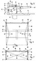
- ein erstes Ausführungsbeispiel eines Tischaufsatzes mit herausklappbaren Ausklappelementen auf einem Arbeitstisch in einer perspektivischen Darstellung,
- Fig. 2
- dasselbe Ausführungsbeispiel in einer seitlichen Darstellung bei eingeklappten Ausklappelementen,
- Fig. 3
- eine Seitenansicht eines zweiten Ausführungsbeispiels mit einem aus der Abstellplatte herausziehbaren Ausziehelement,
- Fig. 4
- eine Seitenansicht eines dritten Ausführungsbeispiels mit rolladenpanzerartig herausziehbaren Ausziehelementen,
- Fig. 5
- eine Seitenansicht eines vierten Ausführungsbeispiels mit unterhalb der Abstellplatte angeordneten, herausziehbaren Ausziehelementen im ausgezogenen Zustand,
- Fig. 6
- das in Fig. 5 dargestellte vierte Ausführungsbeispiel in einer Draufsicht von oben und
- Fig. 7
- dasselbe Ausführungsbeispiel in einer Draufsicht von oben bei eingeschobenen Ausziehelementen.
- Fig. 1
- 1 shows a perspective view of a first embodiment of a table attachment with fold-out fold-out elements on a work table,
- Fig. 2
- the same embodiment in a side view with the fold-out elements folded in,
- Fig. 3
- 2 shows a side view of a second exemplary embodiment with a pull-out element which can be pulled out of the storage plate,
- Fig. 4
- 2 shows a side view of a third exemplary embodiment with pull-out elements which can be pulled out in the manner of roller shutters,
- Fig. 5
- a side view of a fourth embodiment with pull-out pull-out elements located underneath the shelf when pulled out,
- Fig. 6
- the fourth embodiment shown in Fig. 5 in a plan view from above and
- Fig. 7
- the same embodiment in a plan view from above with inserted pull-out elements.
Bei dem in den Fig. 1 und 2 dargestellten ersten Ausführungsbeispiel besteht ein Arbeitstisch 10, beispielsweise ein üblicher Schreib- oder Computertisch, aus einer Arbeitsplatte 11, die von zwei an den Schmalseitenbereichen angeordneten Standfüßen 12 getragen wird. Anstelle des dargestellten Arbeitstisches 10 können selbstverständlich auch andere übliche Arbeitstische treten, beispielsweise auch Arbeitstische mit vier Füßen.In the first exemplary embodiment shown in FIGS. 1 and 2, a work table 10, for example a conventional desk or computer desk, consists of a
Auf der Arbeitsplatte 11 des Arbeitstisches 10 ist ein Tischaufsatz 13 angeordnet. Dieser besteht im wesentlichen aus einer Abstellplatte 14, die mittels Haltefüßen 15 beabstandet und im wesentlichen parallel zur Arbeitsplatte 11 oberhalb dieser angeordnet ist. Diese Abstellplatte 14 besitzt eine Länge, die im wesentlichen der der Arbeitsplatte 11 entspricht, jedoch eine wesentlich geringere Tiefe, und ist oberhalb des dem Benutzer des Arbeitstisches 10 abgewandten hinteren Bereich der Arbeitsplatte 11 positioniert. Die Haltefüße 15 sind in nicht näher dargestellter Weise an der Arbeitsplatte 11 fixiert, beispielsweise durch Halteschrauben, Haltebügel, Schraubklemmen od.dgl.A
An der Abstellplatte 14 sind zwei platten- bzw. leistenartige Ausklappelemente 16, 17 über Gelenke oder Scharniere 18 ausklappbar angeordnet, wobei diese Ausklappelemente 16, 17 im eingeklappten Zustand unter der Abstellplatte 14 positioniert sind, wie dies Fig. 2 zeigt. An den freien Eckbereichen des von der Abstellplatte 14 entfernten Ausklappelements 17 sind ebenfalls Haltefüße 19 angeordnet, deren Höhe im wesentlichen der Höhe der Haltefüße 15 entspricht. Diese Haltefüße 19 sind jedoch nicht an der Arbeitsplatte 11 fixiert, sondern verschiebbar auf dieser angeordnet, wozu am unteren Endbereich Gleitelemente 20 angeordnet sind.On the
Im ausgeklappten Zustand bilden die beiden Ausklappelemente 16, 17 zusammen mit der Abstellplatte 14 eine ebene Platte, deren Größe im wesentlichen der der Arbeitsplatte 11 entspricht. Die Scharniere 18 sind dabei so ausgebildet, daß die Ausklappelemente 16, 17 zusammen mit der Abstellplatte 14 eine selbsthaltende Platte bilden. Während im eingeklappten Zustand gemäß Fig. 2 der Arbeitstisch 10 seine übliche Funktion besitzt und der Tischaufsatz 13 lediglich durch die Abstellplatte 14 eine zusätzliche Abstellfläche in einer höheren Ebene schafft, verwandelt der Tischaufsatz 13 in seinem ausgeklappten Zustand den Arbeitstisch 10 zu einem Stehpult gemäß Fig. 1, um wahlweise die Arbeit im sitzenden oder stehenden Zustand ausführen zu können. Soll wieder zur sitzenden Tätigkeit zurückgekehrt werden, so ist es lediglich erforderlich, durch Einklappen der Ausklappelemente 16, 17 und Zurückschieben der Haltefüße 19 den in Fig. 2 dargestellten Zustand wiederherzustellen. Auf der Abstellplatte 14 abgestellte Gegenstände können im ein- und ausgeklappten Zustand dort stehen bleiben.In the unfolded state, the two fold-out
Sowohl die Haltefüße 15 als auch die Haltefüße 19 sind höhenverstellbar, um die Höhe des Tischaufsatzes 13 an die gewünschten Erfordernisse anpassen zu können. Dabei ist es auch möglich, unterschiedliche Höhen einzustellen, um beispielsweise eine Schrägfläche zu realisieren.Both the holding
Anstelle speziell ausgebildeter Scharniere 18 können auch einfachere Scharniere verwendet werden, und die ebene Fläche der durch die ausgeklappten Ausklappelemente 16, 17 und die Abstellplatte 14 gebildeten Platte wird durch nicht dargestellte teleskopartig ausfahrbare Führungsrohre gebildet, auf denen die Ausklappelemente 16, 17 aufliegen. Dabei können beispielsweise die Haltefüße 19 an den freien Endbereichen dieser ausfahrbaren Führungsrohre befestigt sein. Derartige teleskopartig ausfahrbare Führungsrohre sind z.B. in Verbindung mit Ausziehtischen bekannt, wobei auch andere Ausziehtischbeschläge hier einsetzbar sind.Instead of specially designed hinges 18, simpler hinges can also be used, and the flat surface of the plate formed by the folded-out fold-out
Gemäß dem in Fig. 3 dargestellten zweiten Ausführungsbeispiel besitzt eine gegenüber dem ersten Ausführungsbeispiel abgewandelte Abstellplatte 21 einen Hohlraum zur Aufnahme eines platten- oder leistenartigen Ausziehelements 22. In Fig. 3 ist der ausgezogene Zustand dargestellt, bei dem das Ausziehelement 22 zusammen mit der Abstellplatte 21 eine vergrößerte Fläche bilden, die im wesentlichen der der Arbeitsplatte 11 des Arbeitstisches 10 entspricht. Im eingeschobenen Zustand des Ausziehelements 22 ist wieder die übliche Funktion des Arbeitstisches 10 hergestellt, und die nun eine gegenüber der Arbeitsplatte 11 eine wesentlich geringere Tiefe aufweisende Abstellplatte 21 dient lediglich noch als zusätzliche Abstellfläche in einer erhöhten Ebene. Die verschiebbaren Haltefüße 19 sind an den freien Eckbereichen des Ausziehelements 22 fixiert.According to the second exemplary embodiment shown in FIG. 3, a
Anstelle eines einzigen Ausziehelements 22 können selbstverständlich auch hier mehrere Ausziehelemente 22 treten, die teleskopartig ineinanderschiebbar bzw. auseinanderziehbar ausgebildet sind. In einer weiteren Abwandlung können auch mehrere Ausziehelemente schuppenartig überlappend oberhalb oder unterhalb der Abstellplatte 21 bzw. der Abstellplatte 14 angeordnet und herausziehbar ausgebildet sein. Auch bei einer solchen Ausführung bietet sich zur Stabilisierung der gebildeten Plattenfläche wenigstens ein teleskopartig ausfahrbares Führungsrohr an.Instead of a single pull-out
Bei dem in Fig. 4 dargestellten dritten Ausführungsbeispiel ist eine Vielzahl von lamellenartigen Ausziehelementen 23 nach Art eines Rolladenpanzers aneinander aufgereiht. Hintere Haltefüße 24, an denen eine Abstellplatte 25 fixiert ist, besitzen im oberen Bereich eine Krümmung 26, entlang der die rolladenpanzerartig aufgereihten Ausziehelemente 23 hinter diesen Haltefüßen 24 nach unten gleiten können, so daß diese Krümmung 26 als Führungskrümmung ausgebildet ist. Zwischen dem oberen horizontalen Bereich der Haltefüße 24 und der Abstellplatte 25 befindet sich ein Zwischenraum für die Ausziehelemente 23. Fig. 4 stellt den herausgezogenen Zustand dar, also den Zustand, bei dem der Arbeitstisch 10 als Stehpult genutzt werden kann. Die vorderen Haltefüße 19 sind am vorderen freien Endbereich der aneinandergereihten Ausziehelemente 23 fixiert. Werden diese Haltefüße 19 nach hinten geschoben, so gleiten die rolladenpanzerartigen Ausziehelemente 23 entlang der hinteren Haltefüße 24 hinter der Arbeitsplatte 11 nach unten. Auch hier können die Ausziehelemente 23 wieder selbsttragend gelenkig aneinander angeordnet sein, oder es sind zusätzliche Mittel zur Versteifung vorgesehen, beispielsweise teleskopartig ausfahrbare Führungsrohre od.dgl.In the third exemplary embodiment shown in FIG. 4, a plurality of lamella-like pull-out
In einer einfacheren Ausführung können anstelle von höhenverstellbaren Haltefüßen selbstverständlich auch starre Haltefüße treten. Die Gleitelemente 20 an den vorderen Haltefüßen 19 können beispielsweise auch als Rollen ausgebildet sein.In a simpler version, rigid holding feet can of course also be used instead of height-adjustable holding feet. The sliding
Bei dem in den Fig. 5 bis 7 dargestellten vierten Ausführungsbeispiel sind zwei vertikale Haltefüße 30 am hinteren Rand der Arbeitsplatte 11 mittels üblicher Klemmvorrichtungen 31 fixiert. An jedem der Haltefüße 30 ist ein Gelenkarm 32 schwenkbar gelagert, in dem sich die Haltefüße 30 durch entsprechende Lagerrohre 33 erstrecken, an denen die Gelenkarme 32 starr fixiert sind. Diese Lagerrohre 33 liegen auf höhenverstellbar an den Haltefüßen 30 angeordneten Lagerringen 34 auf. Zur Höhenverstellbarkeit der Lagerringe 34 und damit der Gelenkarme 32 dienen Steckelemente 35, die horizontal durch die Lagerringe 34 und durch in verschiedenen Höhenpositionen angeordnete Querbohrungen 36 variabel steckbar sind. Selbstverständlich können die Lagerringe 34 auch andere bekannte Höhenverstellvorrichtungen besitzen.In the fourth exemplary embodiment shown in FIGS. 5 to 7, two vertical holding
Über den Lagerrohren 33 sind Halterohre 37 auf die Haltefüße 30 aufgesteckt und stützen sich nach unten an den Lagerrohren 33 ab. An diesen Halterohren 37 ist je eine beispielsweise aus Blech bestehende Haltewandung 38 fixiert, wobei die beiden Haltewandungen 38 parallel zueinander ausgerichtet sind und zwischen sich eine Abstellplatte 39 halten, die somit in der gewünschten Höhe von hinten her die Arbeitsplatte 11 übergreift. Die Halterohre 37 sind oberhalb der Abstellplatte 39 durch eine stabilisierende Querstange 40 miteinander verbunden. Die Haltewandungen 38 dienen neben der Fixierung der Abstellplatte 39 auch als seitliche Haltewandung für auf der Abstellplatte 39 aufgestellte Gegenstände. Entsprechend dient die Querstange 40 als hinterer Anschlag und hintere Abstützung für solche Gegenstände.Holding
An den von den Halterohren 37 entfernten vertikalen Endkanten der Haltewandungen 38 sind vertikale Haltefüße 41 fixiert, die ebenfalls eine Höhenverstelleinrichtung 42 besitzen und sich mit ihrem unteren Ende auf der Arbeitsplatte 11 abstützen.Vertical holding
Unterhalb der Abstellplatte 39 sind zwei ausziehbare plattenförmige Ausziehelemente 43, 44 angeordnet. Dabei liegt das im ausgezogenen Zustand vordere Ausziehelement 44 immer auf den Gelenkarmen 32 auf, während das hintere Ausziehelement 43 am hinteren Endbereich zwei seitlich abstehende Führungsbolzen 45 besitzt, die in horizontalen Schlitzen 46 der Haltewandungen 38 geführt sind. Die beiden Ausziehelemente 43, 44 sind miteinander über ein flexibles Band 47 verbunden, das an den Unterseiten der beiden Ausziehelemente 43, 44 fixiert ist, am hinteren Ausziehelement 43 allerdings nur am hintersten Bereich, damit das vordere Ausziehelement 44 unter das hintere Ausziehelement 43 geschoben werden kann. Hierzu verlaufen die im ausgezogenen Zustand gemäß Fig. 5 aneinanderliegenden Stoßkanten der beiden Ausziehelemente 43, 44 schräg. Weiterhin sind die Schlitze 46 so weit oberhalb der Auflageebene auf den Gelenkarmen 32 angeordnet, damit sich das vordere Ausziehelement 44 unter das hintere Ausziehelement 43 schieben läßt. An den beiden vorderen Eckbereichen des vorderen Ausziehelements 44 sind Haltebolzen oder Halteschrauben 48 angeordnet, die gelenkig in die vorderen freien Endbereiche der Gelenkarme 32 eingreifen. Die Gelenkarme 32 weisen ungefähr mittig ein Schwenkgelenk 49 auf, wobei die Länge der Gelenkarme 32 so bemessen ist, daß im ganz ausgezogenen Zustand gemäß den Fig. 5 und 6 die Gelenkarme 32 immer noch nicht gestreckt, sondern noch etwas eingeknickt sind, um eine hohe Stabilität der Anordnung und ein problemloses Einscheiben der Ausziehelemente zu gewährleisten.Two pull-out plate-shaped pull-out
Wird ausgehend von der ausgezogenen Position gemäß Fig. 6 das vordere Ausziehelement 44 in Richtung der Abstellplatte 39 eingeschoben, so werden die Gelenkarme 32 so zusammengeschoben, daß sich ihre beiden Schwenkgelenke 49 immer mehr annähern. Dabei wird zunächst das hintere Ausziehelement 43 durch das vordere Ausziehelement 44 miteingeschoben, und zwar so lange, bis die Führungsbolzen 45 am hinteren Ende der Schlitze 46 angelangt sind, also bis das hintere Ausziehelement 43 ganz eingeschoben ist. Infolge der schrägen Stoßkanten zwischen den Ausziehelementen 43, 44 gleitet nun das vordere Ausziehelement 44 unter das hintere Ausziehelement, das dadurch aus seiner Schrägposition in eine horizontale Position oberhalb des vorderen Ausziehelements 44 angehoben wird. Das vordere Ausziehelement 44 kann nun ebenfalls ganz eingeschoben werden.Starting from the extended position shown in FIG. 6 the front pull-out
Beim Ausziehen läuft der umgekehrte Vorgang ab. Zunächst wird ausgehend von der in Fig. 7 dargestellten eingeschobenen Position das vordere Ausziehelement 44 herausgezogen, wobei sich die Gelenkarme 32 strecken. Erreicht die hintere Endkante des vorderen Ausziehelements 44 die vordere Endkante des hinteren Ausziehelements 43, so rutscht das hintere Ausziehelement 43 mit seinem vorderen Bereich nach unten, und die beiden schrägen Stoßkanten liegen wieder aneinander. Beim weiteren Ausziehen des vorderen Ausziehelements 44 wird das hintere Ausziehelement 43 mitherausgezogen, da zum Zeitpunkt des Herabrutschens des hinteren Ausziehelements 43 das Band 47 gespannt ist. Die Herausziehbewegung endet beim Erreichen des vorderen Endes der Schlitze 46 durch die Führungsbolzen 45. Der Tischaufsatz 13 ist jedoch auch in jeder Zwischenstellung voll funktionsfähig.The reverse process takes place when you pull out. First, starting from the inserted position shown in FIG. 7, the front pull-out
In einer alternativen Ausgestaltung ist es auch möglich, die Schlitze 46 so schräg nach unten verlaufen zu lassen, daß das hintere Ausziehelement 43 im ausgezogenen Zustand ebenfalls horizontal auf den Gelenkarmen 32 aufliegt. Anstelle von zwei Ausziehelementen kann prinzipiell auch eine größere Anzahl von Ausziehelementen oder auch nur ein einziges Ausziehelement vorgesehen sein.In an alternative embodiment, it is also possible to allow the
Anstelle des Bandes 47 können auch andere entsprechende Kopplungseinrichtungen zwischen den Ausziehelementen 43, 44 treten, die beim Herausziehen eine kraftschlüssige Verbindung und beim Einschieben ein Übereinanderschieben gewährleisten, z.B. Einrastvorrichtungen.Instead of the
Es ist selbstverständlich auch möglich, an den vorderen Enden der Gelenkarme 32 bzw. am vorderen Ausziehelement 44 verschiebbare Haltefüße gemäß den vorherigen Ausführungsbeispielen anzubringen. Entsprechend können auch bei den bisherigen Ausführungsbeispielen alle Haltefüße an der jeweiligen Abstellplatte fixiert sein, oder es werden kombinierte Lösungen realisiert.It is of course also possible to attach movable holding feet according to the previous exemplary embodiments to the front ends of the articulated
In Abweichung zum in Fig. 1 dargestellten ersten Ausführungsbeispiel kann die Breite des gesamten Tischaufsatzes 13 auch geringer sein als die Breite der Arbeitsplatte 11, um beispielsweise seitlich noch einen Bildschirm od.dgl. aufzustellen.In deviation from the first exemplary embodiment shown in FIG. 1, the width of the
Gemäß Fig. 6 können am vorderen Bereich des vorderen Ausziehelements 44 noch schwenkbare Köcher 50 zur Aufnahme von Schreibutensilien angeordnet sein, die unter dieses Ausziehelement 44 geschwenkt werden können, wenn sie nicht benötigt werden. Anstelle von Köchern können auch Schalen oder andere Aufnahmevorrichtungen treten, wobei diese auch bei den anderen Ausführungsbeispielen in entsprechender Weise realisiert sein können,According to FIG. 6, swiveling
Auf der Abstellplatte 39 können in nicht dargestellter Weise stapelbare oder nichtstapelbare Schalen zur Aufnahme von Formularen oder sonstigen Dingen angeordnet sein, die beispielsweise an der Querstange 40 fixiert sein können.On the
Claims (15)
Applications Claiming Priority (2)
| Application Number | Priority Date | Filing Date | Title |
|---|---|---|---|
| DE19617536 | 1996-05-02 | ||
| DE19617536A DE19617536A1 (en) | 1996-05-02 | 1996-05-02 | Table attachment for work tables |
Publications (2)
| Publication Number | Publication Date |
|---|---|
| EP0804887A1 true EP0804887A1 (en) | 1997-11-05 |
| EP0804887B1 EP0804887B1 (en) | 2000-09-13 |
Family
ID=7793062
Family Applications (1)
| Application Number | Title | Priority Date | Filing Date |
|---|---|---|---|
| EP97107243A Expired - Lifetime EP0804887B1 (en) | 1996-05-02 | 1997-05-01 | Superstructure for worktables |
Country Status (3)
| Country | Link |
|---|---|
| EP (1) | EP0804887B1 (en) |
| AT (1) | ATE196226T1 (en) |
| DE (2) | DE19617536A1 (en) |
Cited By (5)
| Publication number | Priority date | Publication date | Assignee | Title |
|---|---|---|---|---|
| CN101803826A (en) * | 2010-04-12 | 2010-08-18 | 王鸣阳 | Folding table |
| US10413053B2 (en) | 2012-05-24 | 2019-09-17 | Varidesk, Llc | Adjustable desk platform |
| KR102093582B1 (en) * | 2019-09-10 | 2020-03-25 | 김승민 | A space utilized computer table with a built-in shelf |
| USD1023624S1 (en) | 2021-08-16 | 2024-04-23 | AMQ Solutions, LLC | Collapsible workstation |
| USD1023627S1 (en) | 2021-08-16 | 2024-04-23 | AMQ Solutions, LLC | Workstation |
Families Citing this family (1)
| Publication number | Priority date | Publication date | Assignee | Title |
|---|---|---|---|---|
| DE19857736C2 (en) * | 1998-10-21 | 2002-12-05 | Haworth Bueroeinrichtung Gmbh | Shielding device for a table arrangement |
Citations (4)
| Publication number | Priority date | Publication date | Assignee | Title |
|---|---|---|---|---|
| CH93481A (en) * | 1921-03-23 | 1922-05-01 | Nef Paul | Typewriter table with an attachment that can be closed with a roller blind. |
| FR1050738A (en) * | 1952-02-12 | 1954-01-11 | Improvements to work tables of the type notably called ministerial office | |
| DE4112180A1 (en) * | 1991-04-13 | 1992-10-15 | Horst Walter Pollehn | Pivoting arm structure for writing desk - has console support mounted on two swivel arms with friction bearing links, funnel shaped trough and pivot pin |
| EP0523310A1 (en) * | 1991-07-17 | 1993-01-20 | Ernst Stadelmann Gesellschaft m.b.H. | Additional desk support |
-
1996
- 1996-05-02 DE DE19617536A patent/DE19617536A1/en not_active Withdrawn
-
1997
- 1997-05-01 EP EP97107243A patent/EP0804887B1/en not_active Expired - Lifetime
- 1997-05-01 AT AT97107243T patent/ATE196226T1/en not_active IP Right Cessation
- 1997-05-01 DE DE59702333T patent/DE59702333D1/en not_active Expired - Fee Related
Patent Citations (4)
| Publication number | Priority date | Publication date | Assignee | Title |
|---|---|---|---|---|
| CH93481A (en) * | 1921-03-23 | 1922-05-01 | Nef Paul | Typewriter table with an attachment that can be closed with a roller blind. |
| FR1050738A (en) * | 1952-02-12 | 1954-01-11 | Improvements to work tables of the type notably called ministerial office | |
| DE4112180A1 (en) * | 1991-04-13 | 1992-10-15 | Horst Walter Pollehn | Pivoting arm structure for writing desk - has console support mounted on two swivel arms with friction bearing links, funnel shaped trough and pivot pin |
| EP0523310A1 (en) * | 1991-07-17 | 1993-01-20 | Ernst Stadelmann Gesellschaft m.b.H. | Additional desk support |
Cited By (5)
| Publication number | Priority date | Publication date | Assignee | Title |
|---|---|---|---|---|
| CN101803826A (en) * | 2010-04-12 | 2010-08-18 | 王鸣阳 | Folding table |
| US10413053B2 (en) | 2012-05-24 | 2019-09-17 | Varidesk, Llc | Adjustable desk platform |
| KR102093582B1 (en) * | 2019-09-10 | 2020-03-25 | 김승민 | A space utilized computer table with a built-in shelf |
| USD1023624S1 (en) | 2021-08-16 | 2024-04-23 | AMQ Solutions, LLC | Collapsible workstation |
| USD1023627S1 (en) | 2021-08-16 | 2024-04-23 | AMQ Solutions, LLC | Workstation |
Also Published As
| Publication number | Publication date |
|---|---|
| DE19617536A1 (en) | 1997-11-06 |
| DE59702333D1 (en) | 2000-10-19 |
| EP0804887B1 (en) | 2000-09-13 |
| ATE196226T1 (en) | 2000-09-15 |
Similar Documents
| Publication | Publication Date | Title |
|---|---|---|
| EP2260229A1 (en) | Height-adjustable equipment stand | |
| EP3200653A1 (en) | Height-adjustable table | |
| EP0663164B1 (en) | Piece of furniture with a stationary board and at least two supplementary boards | |
| DE4021248A1 (en) | KIT FOR THE PRODUCTION OF OFFICE WORK TABLES | |
| EP0804887B1 (en) | Superstructure for worktables | |
| EP0372399A2 (en) | Telescopic supporting arm adjustable in length | |
| EP2896320B1 (en) | Table extension fitting for a table with a table top and an extension plate and table with a table extension fitting | |
| DE2320344B2 (en) | Swivel mechanism for retractable kitchen machines | |
| EP0482416A1 (en) | Furniture, especially a table | |
| DE202019105069U1 (en) | Table with a table top and a tabletop supplement | |
| EP1747733B1 (en) | A piece of furniture, in particular an office desk | |
| DE2401839C3 (en) | Extending table with a fixed central plate, at least one extending plate and two carriages | |
| DE19641621C2 (en) | Scissor lattice body for drawer element | |
| EP1391165A1 (en) | Table | |
| DE3111920A1 (en) | Desk with height-adjustable desk top | |
| DE2717729A1 (en) | Combined desk and chair unit with telescopic guide rails - has roller-mounted foot plate on chair transferring load to floor | |
| AT408309B (en) | SEAT, LOUNGE, FURNITURE | |
| DE202022104085U1 (en) | furniture | |
| DE102016120521B4 (en) | folding table | |
| EP0986975A1 (en) | Carrying frame, in particular for computer display | |
| AT17997U2 (en) | Desk | |
| DE10120106B4 (en) | worktable | |
| DE202015007583U1 (en) | Sales and presentation equipment | |
| DE102020125883A1 (en) | Stowable table | |
| AT16851U1 (en) | table |
Legal Events
| Date | Code | Title | Description |
|---|---|---|---|
| PUAI | Public reference made under article 153(3) epc to a published international application that has entered the european phase |
Free format text: ORIGINAL CODE: 0009012 |
|
| AK | Designated contracting states |
Kind code of ref document: A1 Designated state(s): AT CH DE DK FR LI NL SE |
|
| 17P | Request for examination filed |
Effective date: 19980416 |
|
| GRAG | Despatch of communication of intention to grant |
Free format text: ORIGINAL CODE: EPIDOS AGRA |
|
| 17Q | First examination report despatched |
Effective date: 19990917 |
|
| GRAG | Despatch of communication of intention to grant |
Free format text: ORIGINAL CODE: EPIDOS AGRA |
|
| GRAH | Despatch of communication of intention to grant a patent |
Free format text: ORIGINAL CODE: EPIDOS IGRA |
|
| GRAH | Despatch of communication of intention to grant a patent |
Free format text: ORIGINAL CODE: EPIDOS IGRA |
|
| GRAA | (expected) grant |
Free format text: ORIGINAL CODE: 0009210 |
|
| AK | Designated contracting states |
Kind code of ref document: B1 Designated state(s): AT CH DE DK FR LI NL SE |
|
| PG25 | Lapsed in a contracting state [announced via postgrant information from national office to epo] |
Ref country code: NL Free format text: LAPSE BECAUSE OF FAILURE TO SUBMIT A TRANSLATION OF THE DESCRIPTION OR TO PAY THE FEE WITHIN THE PRESCRIBED TIME-LIMIT Effective date: 20000913 Ref country code: FR Free format text: LAPSE BECAUSE OF FAILURE TO SUBMIT A TRANSLATION OF THE DESCRIPTION OR TO PAY THE FEE WITHIN THE PRESCRIBED TIME-LIMIT Effective date: 20000913 |
|
| REF | Corresponds to: |
Ref document number: 196226 Country of ref document: AT Date of ref document: 20000915 Kind code of ref document: T |
|
| REG | Reference to a national code |
Ref country code: CH Ref legal event code: EP |
|
| REF | Corresponds to: |
Ref document number: 59702333 Country of ref document: DE Date of ref document: 20001019 |
|
| PG25 | Lapsed in a contracting state [announced via postgrant information from national office to epo] |
Ref country code: SE Free format text: LAPSE BECAUSE OF FAILURE TO SUBMIT A TRANSLATION OF THE DESCRIPTION OR TO PAY THE FEE WITHIN THE PRESCRIBED TIME-LIMIT Effective date: 20001213 Ref country code: DK Free format text: LAPSE BECAUSE OF FAILURE TO SUBMIT A TRANSLATION OF THE DESCRIPTION OR TO PAY THE FEE WITHIN THE PRESCRIBED TIME-LIMIT Effective date: 20001213 |
|
| NLV1 | Nl: lapsed or annulled due to failure to fulfill the requirements of art. 29p and 29m of the patents act | ||
| EN | Fr: translation not filed | ||
| PG25 | Lapsed in a contracting state [announced via postgrant information from national office to epo] |
Ref country code: AT Free format text: LAPSE BECAUSE OF NON-PAYMENT OF DUE FEES Effective date: 20010501 |
|
| PGFP | Annual fee paid to national office [announced via postgrant information from national office to epo] |
Ref country code: DE Payment date: 20010502 Year of fee payment: 5 |
|
| PG25 | Lapsed in a contracting state [announced via postgrant information from national office to epo] |
Ref country code: LI Free format text: LAPSE BECAUSE OF NON-PAYMENT OF DUE FEES Effective date: 20010531 Ref country code: CH Free format text: LAPSE BECAUSE OF NON-PAYMENT OF DUE FEES Effective date: 20010531 |
|
| PLBE | No opposition filed within time limit |
Free format text: ORIGINAL CODE: 0009261 |
|
| STAA | Information on the status of an ep patent application or granted ep patent |
Free format text: STATUS: NO OPPOSITION FILED WITHIN TIME LIMIT |
|
| 26N | No opposition filed | ||
| REG | Reference to a national code |
Ref country code: CH Ref legal event code: PL |
|
| PG25 | Lapsed in a contracting state [announced via postgrant information from national office to epo] |
Ref country code: DE Free format text: LAPSE BECAUSE OF NON-PAYMENT OF DUE FEES Effective date: 20021203 |