EP0804887A1 - Superstructure pour tables de travail - Google Patents
Superstructure pour tables de travail Download PDFInfo
- Publication number
- EP0804887A1 EP0804887A1 EP97107243A EP97107243A EP0804887A1 EP 0804887 A1 EP0804887 A1 EP 0804887A1 EP 97107243 A EP97107243 A EP 97107243A EP 97107243 A EP97107243 A EP 97107243A EP 0804887 A1 EP0804887 A1 EP 0804887A1
- Authority
- EP
- European Patent Office
- Prior art keywords
- pull
- storage plate
- attachment according
- table attachment
- elements
- Prior art date
- Legal status (The legal status is an assumption and is not a legal conclusion. Google has not performed a legal analysis and makes no representation as to the accuracy of the status listed.)
- Granted
Links
Images

Classifications
-
- A—HUMAN NECESSITIES
- A47—FURNITURE; DOMESTIC ARTICLES OR APPLIANCES; COFFEE MILLS; SPICE MILLS; SUCTION CLEANERS IN GENERAL
- A47B—TABLES; DESKS; OFFICE FURNITURE; CABINETS; DRAWERS; GENERAL DETAILS OF FURNITURE
- A47B17/00—Writing-tables
- A47B17/03—Writing-tables with substantially horizontally extensible or adjustable parts other than drawers, e.g. leaves
- A47B17/033—Writing-tables with substantially horizontally extensible or adjustable parts other than drawers, e.g. leaves with parts added to the original furniture to enlarge its surface
-
- A—HUMAN NECESSITIES
- A47—FURNITURE; DOMESTIC ARTICLES OR APPLIANCES; COFFEE MILLS; SPICE MILLS; SUCTION CLEANERS IN GENERAL
- A47B—TABLES; DESKS; OFFICE FURNITURE; CABINETS; DRAWERS; GENERAL DETAILS OF FURNITURE
- A47B19/00—Reading-desks; Lecterns; Pulpits, i.e. free-standing
-
- A—HUMAN NECESSITIES
- A47—FURNITURE; DOMESTIC ARTICLES OR APPLIANCES; COFFEE MILLS; SPICE MILLS; SUCTION CLEANERS IN GENERAL
- A47B—TABLES; DESKS; OFFICE FURNITURE; CABINETS; DRAWERS; GENERAL DETAILS OF FURNITURE
- A47B21/00—Tables or desks for office equipment, e.g. typewriters, keyboards
- A47B21/03—Tables or desks for office equipment, e.g. typewriters, keyboards with substantially horizontally extensible or adjustable parts other than drawers, e.g. leaves
-
- A—HUMAN NECESSITIES
- A47—FURNITURE; DOMESTIC ARTICLES OR APPLIANCES; COFFEE MILLS; SPICE MILLS; SUCTION CLEANERS IN GENERAL
- A47B—TABLES; DESKS; OFFICE FURNITURE; CABINETS; DRAWERS; GENERAL DETAILS OF FURNITURE
- A47B37/00—Tables adapted for other particular purposes
- A47B2037/005—Tables specially adapted for laboratories
Definitions
- the invention relates to a table attachment for work tables, with a storage plate and spacing devices for positioning the storage plate above the rear area of the worktop of the work table facing away from the user, the storage plate having a smaller depth with respect to the worktop.
- Such table attachments are known, for example, in computer work tables, in particular to position the monitor at a certain height.
- the known table attachments are usually fixed in a height-adjustable manner on the worktop or on the work table.
- the table top is equipped with means for reversibly increasing the depth of the storage plate to the front to the front worktop area for optional formation of a desk-like table arrangement.
- Existing work tables can also be retrofitted with the table attachment according to the invention, so that a standing desk can be realized with relatively little conversion work and financial outlay, even when space is limited.
- the table top can also be provided from the start for new tables.
- the table top according to the invention gives a work table a double function: in the enlarged state, the table top converts the work table into a standing desk, and in the non-enlarged state it forms an additional part of the normal use of the work table when the user is seated increased second storage space. This is also retained in the enlarged state, so that, for example, a monitor located on the storage plate can maintain its position when enlarged relative to the standing desk.
- the table attachment can also be completely removed from the work table at least temporarily, for example if its entire area is required for spreading out large drawings or the like.
- plate-like or strip-like fold-out elements are arranged on the storage plate, which are preferably connected to one another and to the storage plate via joints or hinges.
- the storage plate can also be provided with at least one plate-like or strip-like pull-out element, the storage plate preferably having a cavity for receiving the at least one pull-out element, or this at least one pull-out element is arranged below the storage plate in the inserted state.
- a plurality of pull-out elements which can be pulled apart in a scale-like manner can also be provided be.
- a plurality of lamella-like pull-out elements can also be lined up in the manner of a roller shutter curtain.
- means are advantageously provided for stiffening the folded-out fold-out elements or extended pull-out elements to form an overall panel.
- These means can in particular be designed as telescopically extendable guide tubes or as pivotable articulated arms, or the fold-out elements or pull-out elements are connected to one another with connecting means which, together with the fold-out or pull-out elements, form a self-supporting plate.
- a particularly favorable constructive embodiment consists in that the pivotable articulated arms are horizontally pivotably arranged on rear holding feet for the storage plate and are attached or coupled with their free end regions to the foremost pull-out element.
- the articulated arms are also pivoted out at the same time, and the foremost pull-out element and the subsequent pull-out elements lie securely and firmly on the articulated arms.
- At least one further pull-out element is coupled to the foremost pull-out element in such a way that when the foremost pull-out element is pulled out, it is pulled out at the same time.
- the pull-out elements lie against one another via inclined surfaces, which offers a double advantage.
- a pushing force is transmitted during insertion, so that the following pull-out elements are also pushed in by the foremost one, and on the other hand, these inclined surfaces allow one of the pull-out elements to push this and the next front pull-out element one under the other when a rear stop is reached.
- the spacing devices are expediently designed as holding feet, at least some of the holding feet being provided with fixing devices for fixing to the worktop.
- the storage plate is equipped with fixable feet on the worktop and the free end area of the fold-out or pull-out elements with slidable feet so that only the latter feet are moved to increase the depth towards the user or then pushed away again have to.
- it is also an alternative to this It is possible to provide the shelf with holding feet that can be fixed on the worktop and preferably with additional holding feet that are supported on the worktop.
- the holding feet are advantageously at least partially height-adjustable. It is therefore also possible to a limited extent to implement an inclined surface, for example.
- a work table 10 for example a conventional desk or computer desk, consists of a worktop 11 which is supported by two feet 12 arranged on the narrow side areas.
- worktable 10 can of course also be used, for example worktables with four feet.
- a table top 13 is arranged on the worktop 11 of the worktable 10.
- This essentially consists of a storage plate 14 which is spaced apart by means of holding feet 15 and is arranged essentially parallel to the worktop 11 above it.
- This storage plate 14 has a length which corresponds essentially to that of the worktop 11, but a substantially smaller depth, and is above the rear region of the worktop which faces away from the user of the worktable 10 11 positioned.
- the holding feet 15 are fixed in a manner not shown on the worktop 11, for example by holding screws, holding brackets, screw terminals or the like.
- two plate-like or strip-like fold-out elements 16, 17 are arranged such that they can be folded out via joints or hinges 18, these fold-out elements 16, 17 being positioned under the deposit plate 14 in the folded state, as shown in FIG. 2.
- Holding feet 19 are also arranged on the free corner regions of the fold-out element 17 removed from the storage plate 14, the height of which essentially corresponds to the height of the holding feet 15. However, these holding feet 19 are not fixed to the worktop 11, but are arranged displaceably thereon, for which purpose sliding elements 20 are arranged at the lower end region.
- the two fold-out elements 16, 17 together with the storage plate 14 form a flat plate, the size of which essentially corresponds to that of the worktop 11.
- the hinges 18 are designed such that the fold-out elements 16, 17 together with the storage plate 14 form a self-holding plate.
- the work table 10 has its usual function and the table attachment 13 creates an additional storage space in a higher level only by the storage plate 14, the table attachment 13 transforms the work table 10 into a standing desk according to FIG. 1 in its unfolded state, in order to be able to carry out the work either sitting or standing. If it is desired to return to the sitting activity, it is only necessary to restore the state shown in FIG. 2 by folding in the fold-out elements 16, 17 and pushing back the holding feet 19. Objects placed on the storage plate 14 can remain there in the folded and unfolded state.
- Both the holding feet 15 and the holding feet 19 are adjustable in height in order to be able to adapt the height of the table top 13 to the desired requirements. It is also possible to set different heights, for example to implement an inclined surface.
- hinges 18 instead of specially designed hinges 18, simpler hinges can also be used, and the flat surface of the plate formed by the folded-out fold-out elements 16, 17 and the storage plate 14 is formed by telescopically extendable guide tubes, on which the fold-out elements 16, 17 rest.
- the holding feet 19 on the free End regions of these extendable guide tubes can be attached.
- Such telescopically extendable guide tubes are known, for example, in connection with pull-out tables, and other pull-out table fittings can also be used here.
- FIG. 3 shows the extended state in which the pull-out element 22 together with the storage plate 21 form an enlarged area which corresponds essentially to that of the worktop 11 of the worktable 10.
- the usual function of the work table 10 is again established, and the storage plate 21, which is now considerably less deep than the work surface 11, merely serves as an additional storage surface in an elevated plane.
- the displaceable holding feet 19 are fixed to the free corner areas of the pull-out element 22.
- a plurality of pull-out elements 22 can of course also be used here, which are designed to be telescopically pushed into one another or pulled apart.
- a plurality of pull-out elements can also be arranged in a scale-like overlapping manner above or below the storage plate 21 or the storage plate 14 and can be designed to be extractable. Even with such an embodiment, at least one telescopically extendable guide tube is suitable for stabilizing the plate surface formed.
- FIG. 4 shows the extracted state, that is to say the state in which the work table 10 can be used as a standing desk.
- the front holding feet 19 are fixed to the front free end region of the pull-out elements 23 lined up.
- roller shutter-like pull-out elements 23 slide down along the rear holding feet 24 behind the worktop 11.
- the pull-out elements 23 can again be arranged in a self-supporting, articulated manner, or additional means for stiffening are provided, for example telescopic guide tubes or the like.
- rigid holding feet can of course also be used instead of height-adjustable holding feet.
- the sliding elements 20 on the front holding feet 19 can also be designed as rollers, for example.
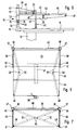
- two vertical holding feet 30 are fixed on the rear edge of the worktop 11 by means of conventional clamping devices 31.
- An articulated arm 32 is pivotally mounted on each of the holding feet 30, in which the holding feet 30 extend through corresponding bearing tubes 33, on which the articulated arms 32 are rigidly fixed.
- These bearing tubes 33 rest on height-adjustable bearing rings 34 arranged on the holding feet 30.
- plug-in elements 35 are used, which can be variably inserted horizontally through the bearing rings 34 and through transverse bores 36 arranged in different height positions.
- the bearing rings 34 can also have other known height adjustment devices.
- Holding tubes 37 are placed on the holding feet 30 above the bearing tubes 33 and are supported downward on the bearing tubes 33.
- a holding wall 38 for example made of sheet metal, is fixed to each of these holding tubes 37, the two holding walls 38 being aligned parallel to one another and holding a storage plate 39 between them, which thus overlaps the worktop 11 from behind at the desired height.
- the holding tubes 37 are connected to one another above the storage plate 39 by a stabilizing cross bar 40.
- the holding walls 38 also serve as a lateral holding wall for objects placed on the storage plate 39. Accordingly, the cross bar 40 serves as a rear stop and rear support for such objects.
- Vertical holding feet 41 are fixed to the vertical end edges of the holding walls 38, which are distant from the holding tubes 37, which also have a height adjustment device 42 and are supported with their lower end on the worktop 11.
- Two pull-out plate-shaped pull-out elements 43, 44 are arranged below the storage plate 39.
- the front pull-out element 44 in the extended state always rests on the articulated arms 32, while the rear one Pull-out element 43 has at the rear end region two laterally projecting guide bolts 45 which are guided in horizontal slots 46 of the holding walls 38.
- the two pull-out elements 43, 44 are connected to one another via a flexible band 47, which is fixed to the undersides of the two pull-out elements 43, 44, but only to the rearmost area on the rear pull-out element 43, so that the front pull-out element 44 is pushed under the rear pull-out element 43 can.
- the abutting edges of the two pull-out elements 43, 44 lying against one another in the extended state according to FIG. 5 run obliquely.
- the slots 46 are arranged so far above the support plane on the articulated arms 32 so that the front pull-out element 44 can be pushed under the rear pull-out element 43.
- Holding bolts or holding screws 48 are arranged on the two front corner regions of the front pull-out element 44 and engage in an articulated manner in the front free end regions of the articulated arms 32.
- the articulated arms 32 have a swivel joint 49 approximately in the middle, the length of the articulated arms 32 being dimensioned such that, in the fully extended state according to FIGS. 5 and 6, the articulated arms 32 are still not stretched, but are somewhat buckled in order to be high To ensure stability of the arrangement and problem-free insertion of the pull-out elements.
- the front pull-out element 44 is pushed in the direction of the storage plate 39, the articulated arms 32 are pushed together in such a way that their two swivel joints 49 come closer and closer together.
- the rear pull-out element 43 is pushed in by the front pull-out element 44 until the guide bolts 45 have reached the rear end of the slots 46, that is to say until the rear pull-out element 43 is fully inserted.
- the front pull-out element 44 now slides under the rear pull-out element, which is thereby raised from its inclined position into a horizontal position above the front pull-out element 44.
- the front pull-out element 44 can now also be fully inserted.
- the width of the entire table attachment 13 can also be less than the width of the worktop 11, for example to include a screen or the like on the side. to set up.
- swiveling quiver 50 for receiving writing utensils can also be arranged on the front area of the front pull-out element 44, which can be swiveled under this pull-out element 44 when they are not required.
- shells or other holding devices can also be used, which can also be implemented in a corresponding manner in the other exemplary embodiments,
- stackable or non-stackable trays for accommodating forms or other things can be arranged in a manner not shown, which can be fixed, for example, to the crossbar 40.
Landscapes
- Tables And Desks Characterized By Structural Shape (AREA)
- Workshop Equipment, Work Benches, Supports, Or Storage Means (AREA)
- Forklifts And Lifting Vehicles (AREA)
Applications Claiming Priority (2)
| Application Number | Priority Date | Filing Date | Title |
|---|---|---|---|
| DE19617536 | 1996-05-02 | ||
| DE19617536A DE19617536A1 (de) | 1996-05-02 | 1996-05-02 | Tischaufsatz für Arbeitstische |
Publications (2)
| Publication Number | Publication Date |
|---|---|
| EP0804887A1 true EP0804887A1 (fr) | 1997-11-05 |
| EP0804887B1 EP0804887B1 (fr) | 2000-09-13 |
Family
ID=7793062
Family Applications (1)
| Application Number | Title | Priority Date | Filing Date |
|---|---|---|---|
| EP97107243A Expired - Lifetime EP0804887B1 (fr) | 1996-05-02 | 1997-05-01 | Superstructure pour tables de travail |
Country Status (3)
| Country | Link |
|---|---|
| EP (1) | EP0804887B1 (fr) |
| AT (1) | ATE196226T1 (fr) |
| DE (2) | DE19617536A1 (fr) |
Cited By (5)
| Publication number | Priority date | Publication date | Assignee | Title |
|---|---|---|---|---|
| CN101803826A (zh) * | 2010-04-12 | 2010-08-18 | 王鸣阳 | 可折叠的桌子 |
| US10413053B2 (en) | 2012-05-24 | 2019-09-17 | Varidesk, Llc | Adjustable desk platform |
| KR102093582B1 (ko) * | 2019-09-10 | 2020-03-25 | 김승민 | 공간활용성이 향상된 선반 내장형 컴퓨터 책상 |
| USD1023624S1 (en) | 2021-08-16 | 2024-04-23 | AMQ Solutions, LLC | Collapsible workstation |
| USD1023627S1 (en) | 2021-08-16 | 2024-04-23 | AMQ Solutions, LLC | Workstation |
Families Citing this family (1)
| Publication number | Priority date | Publication date | Assignee | Title |
|---|---|---|---|---|
| DE19857736C2 (de) * | 1998-10-21 | 2002-12-05 | Haworth Bueroeinrichtung Gmbh | Abschirmeinrichtung für eine Tischanordnung |
Citations (4)
| Publication number | Priority date | Publication date | Assignee | Title |
|---|---|---|---|---|
| CH93481A (de) * | 1921-03-23 | 1922-05-01 | Nef Paul | Schreibmaschinentisch mit durch Rolljalousie verschliessbarem Aufsatz. |
| FR1050738A (fr) * | 1952-02-12 | 1954-01-11 | Perfectionnements aux tables de travail du type notamment dénommé bureau ministre | |
| DE4112180A1 (de) * | 1991-04-13 | 1992-10-15 | Horst Walter Pollehn | Schwenkarmkonstruktion zur anordnung an einen schreibtisch |
| EP0523310A1 (fr) * | 1991-07-17 | 1993-01-20 | Ernst Stadelmann Gesellschaft m.b.H. | Support additionnel de bureau |
-
1996
- 1996-05-02 DE DE19617536A patent/DE19617536A1/de not_active Withdrawn
-
1997
- 1997-05-01 EP EP97107243A patent/EP0804887B1/fr not_active Expired - Lifetime
- 1997-05-01 AT AT97107243T patent/ATE196226T1/de not_active IP Right Cessation
- 1997-05-01 DE DE59702333T patent/DE59702333D1/de not_active Expired - Fee Related
Patent Citations (4)
| Publication number | Priority date | Publication date | Assignee | Title |
|---|---|---|---|---|
| CH93481A (de) * | 1921-03-23 | 1922-05-01 | Nef Paul | Schreibmaschinentisch mit durch Rolljalousie verschliessbarem Aufsatz. |
| FR1050738A (fr) * | 1952-02-12 | 1954-01-11 | Perfectionnements aux tables de travail du type notamment dénommé bureau ministre | |
| DE4112180A1 (de) * | 1991-04-13 | 1992-10-15 | Horst Walter Pollehn | Schwenkarmkonstruktion zur anordnung an einen schreibtisch |
| EP0523310A1 (fr) * | 1991-07-17 | 1993-01-20 | Ernst Stadelmann Gesellschaft m.b.H. | Support additionnel de bureau |
Cited By (5)
| Publication number | Priority date | Publication date | Assignee | Title |
|---|---|---|---|---|
| CN101803826A (zh) * | 2010-04-12 | 2010-08-18 | 王鸣阳 | 可折叠的桌子 |
| US10413053B2 (en) | 2012-05-24 | 2019-09-17 | Varidesk, Llc | Adjustable desk platform |
| KR102093582B1 (ko) * | 2019-09-10 | 2020-03-25 | 김승민 | 공간활용성이 향상된 선반 내장형 컴퓨터 책상 |
| USD1023624S1 (en) | 2021-08-16 | 2024-04-23 | AMQ Solutions, LLC | Collapsible workstation |
| USD1023627S1 (en) | 2021-08-16 | 2024-04-23 | AMQ Solutions, LLC | Workstation |
Also Published As
| Publication number | Publication date |
|---|---|
| ATE196226T1 (de) | 2000-09-15 |
| EP0804887B1 (fr) | 2000-09-13 |
| DE19617536A1 (de) | 1997-11-06 |
| DE59702333D1 (de) | 2000-10-19 |
Similar Documents
| Publication | Publication Date | Title |
|---|---|---|
| EP2260229A1 (fr) | Support pour instruments, réglable en hauteur | |
| EP3200653A1 (fr) | Table réglable en hauteur | |
| EP0663164B1 (fr) | Meuble muni d'un plateau fixe et d'au moins deux plateaux supplémentaires | |
| DE4021248A1 (de) | Bausatz zur herstellung von buero-arbeitstischen | |
| EP0804887B1 (fr) | Superstructure pour tables de travail | |
| EP0372399A2 (fr) | Bras de support télescopique réglable en longueur | |
| CH661420A5 (de) | Zusammenschiebbarer tisch. | |
| EP2896320B1 (fr) | Ferrure de rallonge de table pour une table dotée d'un plateau de table et d'un plateau coulissant et table dotée d'une ferrure de rallonge de table | |
| DE2320344B2 (de) | Schwenkmechanik für versenkbare Küchenmaschinen | |
| EP0482416A1 (fr) | Meuble, en particulier une table | |
| DE202019105069U1 (de) | Tisch mit einer Tischplatte und einem Tischplattenergänzungsteil | |
| EP1747733B1 (fr) | Meuble, en particulier un table de bureau | |
| DE2401839C3 (de) | Ausziehtisch mit einer festen Mittelplatte, wenigstens einer Ausziehplatte und zwei Schlitten | |
| DE19641621C2 (de) | Scherengitterkorpus für Schubladenelement | |
| EP1391165A1 (fr) | Table | |
| DE3111920A1 (de) | Arbeitstisch mit hoehenverstellbarer tischplatte | |
| DE2717729A1 (de) | Aus tisch, bzw. arbeitsplatte o.dgl. und stuhl bestehendes moebel | |
| AT408309B (de) | Sitz-liege-möbel | |
| DE202022104085U1 (de) | Möbel | |
| DE102016120521B4 (de) | Klapptisch | |
| AT17997U2 (de) | Schreibtisch | |
| DE10120106B4 (de) | Arbeitstisch | |
| DE202015007583U1 (de) | Verkaufs- und Präsentationseinrichtung | |
| DE102020125883A1 (de) | VerstaubarerTisch | |
| AT16851U1 (de) | Tisch |
Legal Events
| Date | Code | Title | Description |
|---|---|---|---|
| PUAI | Public reference made under article 153(3) epc to a published international application that has entered the european phase |
Free format text: ORIGINAL CODE: 0009012 |
|
| AK | Designated contracting states |
Kind code of ref document: A1 Designated state(s): AT CH DE DK FR LI NL SE |
|
| 17P | Request for examination filed |
Effective date: 19980416 |
|
| GRAG | Despatch of communication of intention to grant |
Free format text: ORIGINAL CODE: EPIDOS AGRA |
|
| 17Q | First examination report despatched |
Effective date: 19990917 |
|
| GRAG | Despatch of communication of intention to grant |
Free format text: ORIGINAL CODE: EPIDOS AGRA |
|
| GRAH | Despatch of communication of intention to grant a patent |
Free format text: ORIGINAL CODE: EPIDOS IGRA |
|
| GRAH | Despatch of communication of intention to grant a patent |
Free format text: ORIGINAL CODE: EPIDOS IGRA |
|
| GRAA | (expected) grant |
Free format text: ORIGINAL CODE: 0009210 |
|
| AK | Designated contracting states |
Kind code of ref document: B1 Designated state(s): AT CH DE DK FR LI NL SE |
|
| PG25 | Lapsed in a contracting state [announced via postgrant information from national office to epo] |
Ref country code: NL Free format text: LAPSE BECAUSE OF FAILURE TO SUBMIT A TRANSLATION OF THE DESCRIPTION OR TO PAY THE FEE WITHIN THE PRESCRIBED TIME-LIMIT Effective date: 20000913 Ref country code: FR Free format text: LAPSE BECAUSE OF FAILURE TO SUBMIT A TRANSLATION OF THE DESCRIPTION OR TO PAY THE FEE WITHIN THE PRESCRIBED TIME-LIMIT Effective date: 20000913 |
|
| REF | Corresponds to: |
Ref document number: 196226 Country of ref document: AT Date of ref document: 20000915 Kind code of ref document: T |
|
| REG | Reference to a national code |
Ref country code: CH Ref legal event code: EP |
|
| REF | Corresponds to: |
Ref document number: 59702333 Country of ref document: DE Date of ref document: 20001019 |
|
| PG25 | Lapsed in a contracting state [announced via postgrant information from national office to epo] |
Ref country code: SE Free format text: LAPSE BECAUSE OF FAILURE TO SUBMIT A TRANSLATION OF THE DESCRIPTION OR TO PAY THE FEE WITHIN THE PRESCRIBED TIME-LIMIT Effective date: 20001213 Ref country code: DK Free format text: LAPSE BECAUSE OF FAILURE TO SUBMIT A TRANSLATION OF THE DESCRIPTION OR TO PAY THE FEE WITHIN THE PRESCRIBED TIME-LIMIT Effective date: 20001213 |
|
| NLV1 | Nl: lapsed or annulled due to failure to fulfill the requirements of art. 29p and 29m of the patents act | ||
| EN | Fr: translation not filed | ||
| PG25 | Lapsed in a contracting state [announced via postgrant information from national office to epo] |
Ref country code: AT Free format text: LAPSE BECAUSE OF NON-PAYMENT OF DUE FEES Effective date: 20010501 |
|
| PGFP | Annual fee paid to national office [announced via postgrant information from national office to epo] |
Ref country code: DE Payment date: 20010502 Year of fee payment: 5 |
|
| PG25 | Lapsed in a contracting state [announced via postgrant information from national office to epo] |
Ref country code: LI Free format text: LAPSE BECAUSE OF NON-PAYMENT OF DUE FEES Effective date: 20010531 Ref country code: CH Free format text: LAPSE BECAUSE OF NON-PAYMENT OF DUE FEES Effective date: 20010531 |
|
| PLBE | No opposition filed within time limit |
Free format text: ORIGINAL CODE: 0009261 |
|
| STAA | Information on the status of an ep patent application or granted ep patent |
Free format text: STATUS: NO OPPOSITION FILED WITHIN TIME LIMIT |
|
| 26N | No opposition filed | ||
| REG | Reference to a national code |
Ref country code: CH Ref legal event code: PL |
|
| PG25 | Lapsed in a contracting state [announced via postgrant information from national office to epo] |
Ref country code: DE Free format text: LAPSE BECAUSE OF NON-PAYMENT OF DUE FEES Effective date: 20021203 |