EP0803970B1 - Méthode de la régulation de vitesse exempt de suroscillations pour des moteurs à courant continu et à courant alternatif - Google Patents
Méthode de la régulation de vitesse exempt de suroscillations pour des moteurs à courant continu et à courant alternatif Download PDFInfo
- Publication number
- EP0803970B1 EP0803970B1 EP97400924A EP97400924A EP0803970B1 EP 0803970 B1 EP0803970 B1 EP 0803970B1 EP 97400924 A EP97400924 A EP 97400924A EP 97400924 A EP97400924 A EP 97400924A EP 0803970 B1 EP0803970 B1 EP 0803970B1
- Authority
- EP
- European Patent Office
- Prior art keywords
- rotary speed
- speed
- load
- deviation
- signal
- Prior art date
- Legal status (The legal status is an assumption and is not a legal conclusion. Google has not performed a legal analysis and makes no representation as to the accuracy of the status listed.)
- Expired - Lifetime
Links
- 238000000034 method Methods 0.000 title claims description 23
- 230000001419 dependent effect Effects 0.000 claims description 3
- 230000001105 regulatory effect Effects 0.000 claims description 3
- 238000013016 damping Methods 0.000 claims description 2
- 230000010355 oscillation Effects 0.000 claims 4
- 230000010354 integration Effects 0.000 description 6
- 238000010586 diagram Methods 0.000 description 5
- 238000009499 grossing Methods 0.000 description 3
- 206010041953 Staring Diseases 0.000 description 2
- 230000004069 differentiation Effects 0.000 description 2
- 238000005259 measurement Methods 0.000 description 2
- 238000005070 sampling Methods 0.000 description 2
- 230000007704 transition Effects 0.000 description 2
- 230000009977 dual effect Effects 0.000 description 1
- 230000000694 effects Effects 0.000 description 1
- 238000005516 engineering process Methods 0.000 description 1
- 238000009434 installation Methods 0.000 description 1
- 230000003534 oscillatory effect Effects 0.000 description 1
Images


Classifications
-
- H—ELECTRICITY
- H02—GENERATION; CONVERSION OR DISTRIBUTION OF ELECTRIC POWER
- H02P—CONTROL OR REGULATION OF ELECTRIC MOTORS, ELECTRIC GENERATORS OR DYNAMO-ELECTRIC CONVERTERS; CONTROLLING TRANSFORMERS, REACTORS OR CHOKE COILS
- H02P29/00—Arrangements for regulating or controlling electric motors, appropriate for both AC and DC motors
- H02P29/0016—Control of angular speed of one shaft without controlling the prime mover
Definitions
- the invention relates to a method for overshoot Speed control of DC and AC motors with subordinate Current or torque control in a rigid drive train or in an oscillatable drive train.
- a PI controller combines the fast reaction of a P controller with correcting an I controller after a fault.
- the integral part ensures the regulation deviation as the difference between the target and the actual value of the controlled variable. Because the integral part of the PI controller is a fast one Change of the control signal does not allow, the integration behavior of Integral component cause for the overshoot of the control signal and thus also the controlled variable.
- the controller is set using the symmetrical optimum method, an overshoot of about 40% of the speed jump after accepted a management thrust, cf. Buxbaum / Schierau, p. 116 ff. If the overshoot is to be smaller, the controller must be set more slowly and the slower the speed control is - the larger the speed Rise and settling time - the greater the drop in speed after a load surge. If an overshoot of the speed is undesirable, then either to avoid a speed surge, for example the Speed setpoint led to a ramp function, or a very slow one Speed control is inevitable. A slowly set speed controller delivers a large drop in speed after a load surge, but it often does is undesirable.
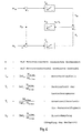
- the entire drive train can be approximated as an elastically coupled two-mass system according to FIG. 5.
- its structural image according to Raatz can be specified as in FIG. 6. 6
- motor torque m M , spring torque m F , load torque m L , motor speed n M and speed n L of the flywheel mass are only the motor speed and motor (active) current, which is a measure of the Torque supplied by the motor is available, while load torque, load speed and spring torque are generally inaccessible for direct measurement or measurement is only possible with great effort.
- the object of the invention is now to achieve a method of type mentioned so that an overshoot of the Speed list values for both a rigid drive train and one oscillatable drive train after a sudden change in the Speed setpoint is avoided, the control dynamics in this Method is better than that of the symmetrical method Optimums set PI controller.
- the essence of the invention is that by the state of Speed deviation pending limitation of the output signal of the Integral element and through the load-compensating pilot control advantageously overshooting the actual speed value after a Jump in the speed setpoint is avoided. At the same time, through the now possible further increase in the proportional gain of the Speed controller after a load surge compared to the known solutions can be kept smaller.
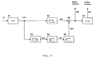
- the circuit arrangement for the speed control with subordinate current or torque control in the case of a rigid drive train consists of components 1 to 11.
- a current or torque controller is designated by 13 and the electrical path is designated by 14.
- Integral behavior is assumed for the mechanical controlled system 15.
- the difference between the specified speed setpoint n setpoint and the measured speed actual value n actual is formed in a first subtractor 1 for the speed deviation ⁇ n, amplified in a proportional element 2 and possibly limited with a limiter 3 in order to then be present to a summer 10 as the first input signal a3.
- the actual speed value n actual is differentiated in a differentiator 7 and then subtracted in a second subtractor 8 from the feedback of the underlying current or torque control, signal a8.
- the determined value a8 corresponds to that on the motor attacking load moment.
- a precontrol signal a9 stands as a second input signal to the summer 10 Available.
- the task of the pilot control signal a9 in the steady state the controlled system corresponds to the integral part of a PI controller: the subordinate current or torque control loop the compensation component to specify according to the load torque while the control deviation ⁇ n is almost zero.
- the task of a control part 6 is, depending on the state of the Speed deviation ⁇ n the limits of a limiter 5, which the maximum or minimum output variable of an integrating element 4 is determined, to influence: they become smaller with increasing speed deviation ⁇ n controlled.
- the speed deviation is in the quasi-stationary range, ie if l ⁇ nl is less than a certain value
- the output signal a62 and the output signal a65 of a block 65 determine the maximum upper limit of the limiter 5.
- in the dynamic range the signal a 62 becomes zero; this closes the limits of the limiter 5, which suppress the integral part of the speed control.
- Blocks 63 to 66 help to avoid the fluttering of the borders.
- Module 63 acts like a two-point switch with hysteresis.
- and a63 0 for
- Block 64 is a timer with a switch-on delay function.
- the value one of the input signal a63 is only after a delay time T at the output of block 64 as Signal a64 before. This will result in unnecessarily frequent switching in the area of Transition phase from the quasi-stationary area to the dynamic area avoided see curves c and d of Fig. 3.
- the signal a64 becomes the signal Signal a65 smoothed, which multiplied by signal a62 to signal a66 as upper limit of the limiter 5 is formed.
- the lower limit as a signal a67 is formed by negating signal a66 in module 67.
- the upper and lower limits of the Limiter 5 determined depending on the state of the speed deviation. In the dynamic state, i.e. if the speed deviation is outside of a certain bandwidth, the limits of the limiter 5 controlled, thereby the integral part of the speed control suppressed, the value of signal a5 is zero and therefore also that Overshoot.
- the stability limit depends on the quality of the measured controlled variable and on the sampling time of the control if the control works digitally.
- the stability limit is defined by the smallest possible integration time constant T l, min at a certain gain factor k or by the greatest possible gain factor k max at a certain integration time constant T l without the speed starting to oscillate.
- the limit gain kmax will be smaller the smaller the integration time constant T l is set.
- the integral component is suppressed in the dynamic state, which corresponds to an infinitely high integration time constant which allows the limit gain kmax to be increased without the control system becoming unstable.
- the increase in gain has an advantageous effect on the rise and fall time as well as on the speed change after a load change, ie there is only a smaller drop in speed after a load surge.
- the output signal a5 of the module 5 is the third input signal of the summer 10.
- a limiter 11 the sum of a3, a5 and a9 may be restricted.
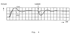
- Fig. 4 shows the speed curve after a guide and a load surge through curve a with a using the symmetrical optimum method Pl controller and curve b with the Speed control method according to the invention.
- FIG. 7 An example of a circuit arrangement for carrying out the method according to the invention in an oscillatable drive train is shown in FIG. 7 as a block diagram and is explained in the following: integral behavior is assumed for the mechanical controlled system 22, for the method presented here the required load torque m L is taken out the inverse model 23 of the structure image in FIG. 6.
- the speed control with subordinate current or torque control consists of modules 1 to 18.
- a current or torque controller is designated 20 and the electrical system is designated 21.
- the difference between the specified engine speed setpoint n target and the measured engine speed actual value n actual is formed in a subtractor 1 for the speed deviation ⁇ n, amplified in a proportional element 2 and possibly limited with a limiter 3, in order then to be present as a first input signal a3 to a first summer 17.
- engine speed n M n actual and engine torque m M
- all variables that are difficult to access are determined: spring torque m F , load torque m L and load speed n L .
- the model parameters shown in FIGS. 5 and 6 are determined by design data of the mechanical system. They can also be determined on the drive if necessary, cf. Langhoff, Jürgen / Raatz, Eckart: Regulated DC drives, 1977, Elitera-Verlag, Berlin, p. 129 ff.
- a second subtractor 9 an integral element 10 with the integration time constant T F and a proportional element 11 of the gain factor 1 / k F together form the inverse model 23 of the PI element of the gain k F and the time constant k F T F shown in FIG. 6
- the pilot control signal a15 has the same task as the integral component of a PI controller: to give the subordinate current or torque control loop the setpoint according to the motor load, while the control deviation ⁇ n is practically zero.
- the function of the control part 6 has already been described in connection with FIG. 1 described.
- the upper and lower Limit of the limiter 5 opened so that the integrator 4 the occurring Can regulate deviation.
- the output signal a5 of the module 5 is the third input signal of the first summer 17.
- a limiter 18 the sum of the signals a3, a5, a15, and a16 possibly restricted.
- Fig. 8 shows the speed curve after a guide and a load surge through curve a with a using the symmetrical optimum method Pl controller and curve b with the Speed control method according to the invention.
Landscapes
- Engineering & Computer Science (AREA)
- Power Engineering (AREA)
- Control Of Electric Motors In General (AREA)
- Control Of Multiple Motors (AREA)
Claims (5)
- Procédé de régulation de vitesse exempte de suroscillations pour des moteurs à courant continu et à courant alternatif équipés d'une régulation de courant en cascade ou régulation de couple à l'intérieur d'une chaíne cinématique à vitesse constante ou d'une chaíne cinématique capable d'osciller
caractérisé en ce
qu'un écart de la valeur effective de la vitesse (nist) par rapport à la valeur de consigne de la vitesse (nsoll) est immédiatement corrigé par un régulateur proportionnel (2), que le couple de charge appliqué est compensé par un signal pilote (a9, a15) fonction de la charge et qu'un écart de vitesse (Δn) est régulé par un circuit d'intégration (4) dont la valeur maximale de sortie (a5) est commandée par la valeur de l'écart de vitesse (Δn), les paramètres vitesse de charge (nL) et couple de charge (mL) étant déterminés, dans une chaíne cinématique capable d'osciller qui agit comme un système à deux masses à couplage élastique pouvant osciller, à l'aide d'un modèle inverse (23) de la chaíne cinématique mécanique. - Procédé selon la revendication 1, caractérisé en ce que, du côté de l'entrée, le circuit d'intégration (4) est monté en parallèle avec le régulateur proportionnel (2).
- Procédé selon la revendication 1, caractérisé en ce que la sortie du régulateur proportionnel (2) est ramenée sur l'entrée du circuit d'intégration (4).
- Procédé selon l'une des revendications 2 ou 3, caractérisé en ce que la valeur maximale de sortie du régulateur proportionnel (4) est limitée à une valeur fixe inférieure à un.
- Procédé selon l'une des revendications 1 ou 4, caractérisé en ce que, en plus du signal de sortie du régulateur proportionnel (2) pour la correction immédiate de la vitesse effective (nist), du signal pilote fonction de la charge (a15) et du signal de sortie (a5) du circuit d'intégration (4) commandé pour la régulation de l'écart de vitesse (Δn), un signal de correction (a16) est généré pour atténuer l'auto-oscillation mécanique en corrigeant l'écart entre la vitesse effective (nist) et la vitesse en charge (nL) déterminée à partir du modèle inverse (23) de la chaíne cinématique mécanique.
Applications Claiming Priority (4)
| Application Number | Priority Date | Filing Date | Title |
|---|---|---|---|
| DE19617866 | 1996-04-24 | ||
| DE19617866A DE19617866A1 (de) | 1996-04-24 | 1996-04-24 | Hochdynamische, überschwingfreie Drehzahlregelung von Motoren mit Lastschwungmasse und elastischer Welle |
| DE19617867 | 1996-04-24 | ||
| DE19617867A DE19617867A1 (de) | 1996-04-24 | 1996-04-24 | Hochdynamischer, überschwingfreier Drehzahlregler |
Publications (3)
| Publication Number | Publication Date |
|---|---|
| EP0803970A2 EP0803970A2 (fr) | 1997-10-29 |
| EP0803970A3 EP0803970A3 (fr) | 1998-04-15 |
| EP0803970B1 true EP0803970B1 (fr) | 2000-10-25 |
Family
ID=26025385
Family Applications (1)
| Application Number | Title | Priority Date | Filing Date |
|---|---|---|---|
| EP97400924A Expired - Lifetime EP0803970B1 (fr) | 1996-04-24 | 1997-04-23 | Méthode de la régulation de vitesse exempt de suroscillations pour des moteurs à courant continu et à courant alternatif |
Country Status (2)
| Country | Link |
|---|---|
| EP (1) | EP0803970B1 (fr) |
| DE (1) | DE59702517D1 (fr) |
Family Cites Families (2)
| Publication number | Priority date | Publication date | Assignee | Title |
|---|---|---|---|---|
| DD116359A1 (fr) * | 1974-12-23 | 1975-11-12 | ||
| DE3871074D1 (de) * | 1987-10-26 | 1992-06-17 | Siemens Ag | Verfahren zur erfassung und regelung eines federmoments sowie einer differenzdrehzahl bei rotatorisch angetriebenen zwei-massen-systemen. |
-
1997
- 1997-04-23 EP EP97400924A patent/EP0803970B1/fr not_active Expired - Lifetime
- 1997-04-23 DE DE59702517T patent/DE59702517D1/de not_active Expired - Fee Related
Also Published As
| Publication number | Publication date |
|---|---|
| DE59702517D1 (de) | 2000-11-30 |
| EP0803970A3 (fr) | 1998-04-15 |
| EP0803970A2 (fr) | 1997-10-29 |
Similar Documents
| Publication | Publication Date | Title |
|---|---|---|
| DE2802224C2 (de) | Schaltungsanordnung zur proportional-integralen Drehzahlregelung einer von einem Elektromotor angetriebenen Arbeitsmaschine mit veränderlicher Belastung | |
| DE69731060T2 (de) | Verfahren und Gerät zur Berechnung und Steuerung von nicht-linearen Störungen in einem Rückführsteuerungssystem | |
| AT518700B1 (de) | Verfahren zum Eindrehen einer Schraube mit einem vorbestimmten Anzugsdrehmoment | |
| DE3877874T2 (de) | Anordnung zur stabilisierung eines leistungssystems. | |
| DE3887062T2 (de) | Servosteuerung. | |
| DE69504457T2 (de) | Leistungssystemstabilisierung für einen Generator | |
| EP3156646B1 (fr) | Éolienne dotee d'un regulateur d'alternateur et de vitesse | |
| DE69403185T2 (de) | Gerät zum Steuern der Schwingungen eines Motors und Verfahren zur Angleichung des gemessenen Geschwindigkeitswerts eines Motors an einem Geschwindigkeitssollwert | |
| DE112007001271T5 (de) | Servoregelvorrichtung | |
| DE3416496C2 (fr) | ||
| EP1203270B1 (fr) | Procede et dispositif d'amortissement de vibrations torsionnelles d'un moteur a combustion interne | |
| DE3708261C2 (fr) | ||
| DE10021626A1 (de) | Verfahren zur Lastpendeldämpfung an Kranen mit reduzierter Sensorik | |
| DE2902376A1 (de) | Einrichtung zur schwingungsdaempfung | |
| DE3026975C2 (de) | Vorrichtung zur Regelung der Drehzahl eines über einen Umrichter gespeisten Induktionsmotors | |
| EP0803970B1 (fr) | Méthode de la régulation de vitesse exempt de suroscillations pour des moteurs à courant continu et à courant alternatif | |
| EP2050187B1 (fr) | Entrainement et procede | |
| DE10248633B4 (de) | Verfahren zur Drehzahl-Regelung einer Antriebseinheit | |
| EP2100196A1 (fr) | Procédé pour adapter des paramètres de réglage d'un entraînement à différents états de fonctionnement | |
| DE19617866A1 (de) | Hochdynamische, überschwingfreie Drehzahlregelung von Motoren mit Lastschwungmasse und elastischer Welle | |
| DE2054049A1 (de) | Regeleinrichtung zum Stabilisieren von Schiffen mit Hilfe aktiver Flossen | |
| DE102004015973B3 (de) | Verfahren zur Steuerung und Regelung einer Brennkraftmaschinen-Generator-Einheit | |
| DE1299452B (de) | Stabilisierung von verzoegerungsarmen Regel- oder Steuerstrecken | |
| DE19617867A1 (de) | Hochdynamischer, überschwingfreier Drehzahlregler | |
| WO2022268780A1 (fr) | Dispositif de commande en boucle fermée pour la commande en boucle fermée d'un ensemble d'alimentation comprenant un moteur à combustion interne et un générateur présentant un raccordement d'entraînement fonctionnel au moteur à combustion interne, agencement de commande en boucle fermée doté d'un tel dispositif de commande en boucle fermée, et procédé de commande en boucle fermée d'un ensemble d'alimentation |
Legal Events
| Date | Code | Title | Description |
|---|---|---|---|
| PUAI | Public reference made under article 153(3) epc to a published international application that has entered the european phase |
Free format text: ORIGINAL CODE: 0009012 |
|
| AK | Designated contracting states |
Kind code of ref document: A2 Designated state(s): BE CH DE FR GB LI NL |
|
| PUAL | Search report despatched |
Free format text: ORIGINAL CODE: 0009013 |
|
| AK | Designated contracting states |
Kind code of ref document: A3 Designated state(s): BE CH DE FR GB LI NL |
|
| 17P | Request for examination filed |
Effective date: 19980401 |
|
| RIN1 | Information on inventor provided before grant (corrected) |
Inventor name: DAO HOANG-MINH |
|
| RAP3 | Party data changed (applicant data changed or rights of an application transferred) |
Owner name: ALCATEL |
|
| RAP3 | Party data changed (applicant data changed or rights of an application transferred) |
Owner name: ALCATEL |
|
| GRAG | Despatch of communication of intention to grant |
Free format text: ORIGINAL CODE: EPIDOS AGRA |
|
| 17Q | First examination report despatched |
Effective date: 19990929 |
|
| GRAG | Despatch of communication of intention to grant |
Free format text: ORIGINAL CODE: EPIDOS AGRA |
|
| GRAH | Despatch of communication of intention to grant a patent |
Free format text: ORIGINAL CODE: EPIDOS IGRA |
|
| GRAH | Despatch of communication of intention to grant a patent |
Free format text: ORIGINAL CODE: EPIDOS IGRA |
|
| GRAA | (expected) grant |
Free format text: ORIGINAL CODE: 0009210 |
|
| AK | Designated contracting states |
Kind code of ref document: B1 Designated state(s): BE CH DE FR GB LI NL |
|
| PG25 | Lapsed in a contracting state [announced via postgrant information from national office to epo] |
Ref country code: NL Free format text: LAPSE BECAUSE OF FAILURE TO SUBMIT A TRANSLATION OF THE DESCRIPTION OR TO PAY THE FEE WITHIN THE PRESCRIBED TIME-LIMIT Effective date: 20001025 Ref country code: GB Free format text: LAPSE BECAUSE OF FAILURE TO SUBMIT A TRANSLATION OF THE DESCRIPTION OR TO PAY THE FEE WITHIN THE PRESCRIBED TIME-LIMIT Effective date: 20001025 Ref country code: FR Free format text: LAPSE BECAUSE OF FAILURE TO SUBMIT A TRANSLATION OF THE DESCRIPTION OR TO PAY THE FEE WITHIN THE PRESCRIBED TIME-LIMIT Effective date: 20001025 |
|
| REG | Reference to a national code |
Ref country code: CH Ref legal event code: EP |
|
| REF | Corresponds to: |
Ref document number: 59702517 Country of ref document: DE Date of ref document: 20001130 |
|
| EN | Fr: translation not filed | ||
| NLV1 | Nl: lapsed or annulled due to failure to fulfill the requirements of art. 29p and 29m of the patents act | ||
| GBV | Gb: ep patent (uk) treated as always having been void in accordance with gb section 77(7)/1977 [no translation filed] |
Effective date: 20001025 |
|
| PG25 | Lapsed in a contracting state [announced via postgrant information from national office to epo] |
Ref country code: BE Free format text: LAPSE BECAUSE OF NON-PAYMENT OF DUE FEES Effective date: 20010430 |
|
| PG25 | Lapsed in a contracting state [announced via postgrant information from national office to epo] |
Ref country code: LI Free format text: LAPSE BECAUSE OF NON-PAYMENT OF DUE FEES Effective date: 20010522 Ref country code: CH Free format text: LAPSE BECAUSE OF NON-PAYMENT OF DUE FEES Effective date: 20010522 |
|
| PLBE | No opposition filed within time limit |
Free format text: ORIGINAL CODE: 0009261 |
|
| STAA | Information on the status of an ep patent application or granted ep patent |
Free format text: STATUS: NO OPPOSITION FILED WITHIN TIME LIMIT |
|
| 26N | No opposition filed | ||
| BERE | Be: lapsed |
Owner name: ALCATEL Effective date: 20010430 |
|
| REG | Reference to a national code |
Ref country code: CH Ref legal event code: PL |
|
| PGFP | Annual fee paid to national office [announced via postgrant information from national office to epo] |
Ref country code: DE Payment date: 20030624 Year of fee payment: 7 |
|
| PG25 | Lapsed in a contracting state [announced via postgrant information from national office to epo] |
Ref country code: DE Free format text: LAPSE BECAUSE OF NON-PAYMENT OF DUE FEES Effective date: 20041103 |