EP0803970A2 - Méthode de la régulation de vitesse exempt de suroscillations pour des moteurs à courant continu et à courant alternatif - Google Patents
Méthode de la régulation de vitesse exempt de suroscillations pour des moteurs à courant continu et à courant alternatif Download PDFInfo
- Publication number
- EP0803970A2 EP0803970A2 EP97400924A EP97400924A EP0803970A2 EP 0803970 A2 EP0803970 A2 EP 0803970A2 EP 97400924 A EP97400924 A EP 97400924A EP 97400924 A EP97400924 A EP 97400924A EP 0803970 A2 EP0803970 A2 EP 0803970A2
- Authority
- EP
- European Patent Office
- Prior art keywords
- speed
- load
- drive train
- actual
- control
- Prior art date
- Legal status (The legal status is an assumption and is not a legal conclusion. Google has not performed a legal analysis and makes no representation as to the accuracy of the status listed.)
- Granted
Links
Images


Classifications
-
- H—ELECTRICITY
- H02—GENERATION; CONVERSION OR DISTRIBUTION OF ELECTRIC POWER
- H02P—CONTROL OR REGULATION OF ELECTRIC MOTORS, ELECTRIC GENERATORS OR DYNAMO-ELECTRIC CONVERTERS; CONTROLLING TRANSFORMERS, REACTORS OR CHOKE COILS
- H02P29/00—Arrangements for regulating or controlling electric motors, appropriate for both AC and DC motors
- H02P29/0016—Control of angular speed of one shaft without controlling the prime mover
Definitions
- the invention relates to a method for overshoot-free speed control of DC and AC motors with subordinate current or torque control.
- Decisive for the control dynamics of a speed control are the rise and fall time of the controlled variable after a speed or a load surge.
- the speed overshoots after a guide impulse and the speed drop after a load impulse cf. Buxbaum, Arne / Schierau, Klaus: Calculation of control loops for drive technology, 4th edition, AEG-Telefunken AG, Berlin, Frankfurt am Main 1980, Figures 11, 12, 177 and 178.
- a PI controller combines the fast reaction of a P controller with the correction of an I controller after a fault.
- the integral component ensures that the control deviation is corrected as the difference between the setpoint and the actual value of the controlled variable. Since the integral component of the PI controller does not permit a rapid change in the control signal, the integration behavior of the integral component is the cause for the overshoot of the control signal and thus also the controlled variable.
- the controller is set according to the symmetrical optimum method, whereby an overshoot range of approx. 40% of the speed jump after a lead impact is accepted, cf. Buxbaum / Schi Lucas, p. 116 ff. If the overshoot is to be smaller, the controller must be set more slowly, and the slower the speed control - i.e. the greater the rise and fall time - the greater the drop in speed after a load surge. If the speed overshoot is undesirable, either a speed surge should be avoided, for example the speed setpoint is led to a ramp function, or a very slow speed control is inevitable. A slowly set speed controller provides a large drop in speed after a load surge, but this is often undesirable.
- the speed controller must be set even more slowly so that the control does not become unstable, cf. Raatz, Eckart: Speed control of a converter-fed DC motor with vibrating mechanics. Techn. Mitt. AEG-Telefunken 60 (1970) 6, pp. 369-372.
- the entire drive train can be approximated as an elastically coupled two-mass system according to FIG. 5.
- its structural image according to Raatz can be specified as in FIG. 6. 6
- motor torque m M , spring torque m F , load torque m L , motor speed n M and speed n L of the flywheel mass are only the motor speed and motor (active) current, which is a measure of the Torque supplied by the motor is available, while load torque, load speed and spring torque are usually available for direct measurement are inaccessible or a measurement is only possible with great effort.
- the object is to be achieved to design a method of the type mentioned in such a way that overshoot of the speed list value is avoided both in the case of a rigid drive train and in the case of an oscillatable drive train after a sudden change in the speed setpoint, the control dynamics in this process is better than that of a PI controller set according to the symmetrical optimum method.
- the essence of the invention is that the limitation of the output signal of the integral element depending on the state of the speed deviation and the load-compensating feedforward control advantageously prevent the overspeed of the actual speed after a jump in the speed setpoint. At the same time, due to the now easily possible increase in the proportional gain of the speed controller, the drop in speed after a load surge can be kept smaller compared to the known solutions.
- the load-compensating feedforward control is determined from the inverse model, which was developed from the structural diagram according to FIG. 6.
- the determined value a8 corresponds to the load torque acting on the motor.
- a pilot control signal a9 is available to summer 10 as a second input signal.
- the task of the pilot control signal a9 in the steady state of the controlled system corresponds to the integral component of a PI controller: the subordinate current or torque control loop to specify the compensation component according to the load torque, while the control deviation ⁇ n is virtually zero.
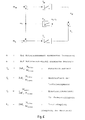
- the task of a control part 6 is to influence the limits of a limiter 5, which determines the maximum or minimum output variable of an integrating element 4, depending on the state of the speed deviation ⁇ n: they are controlled smaller with increasing speed deviation ⁇ n.
- the speed deviation is in the quasi-stationary range, ie if l ⁇ nl is less than a certain value
- the output signal a62 and the output signal a65 of a block 65 determine the maximum upper limit of the limiter 5.
- in the dynamic range the signal a 62 becomes zero; this closes the limits of the limiter 5, which suppress the integral part of the speed control.
- the transition from the quasi-stationary area to the dynamic area and vice versa of the curve of the dependent variable a62 is provided with smoothing or at least with a ramp function.
- Blocks 63 to 66 help to avoid the fluttering of the borders.
- Module 63 acts like a two-point switch with hysteresis.
- and a63 0 for
- Block 64 is a timer with a switch-on delay function.
- the value one of the input signal a63 is only present as signal a64 after a delay time T at the output of the module 64. This avoids an unnecessarily frequent switching in the area of the transition phase from the quasi-stationary area to the dynamic area, see curves c and d of FIG. 3.
- the signal a64 is smoothed into the signal signal a65, which multiplied by the signal a62 to signal a66 as the upper limit of the limiter 5.
- the lower limit as signal a67 is formed by negating signal a66 in module 67.
- the upper and lower limits of the limiter 5 are determined as a function of the state of the speed deviation.
- the limits of the limiter 5 are controlled, this suppresses the integral part of the speed control, the value of the signal a5 is zero and thus the overshoot.
- the stability limit depends on the quality of the measured controlled variable and on the sampling time of the control if the control works digitally.
- the stability limit is defined by the smallest possible integration time constant T l, min at a certain gain factor k or by the greatest possible gain factor k max at a certain integration time constant T l without the speed starting to oscillate.
- the limit gain kmax will be smaller the smaller the integration time constant T l is set.
- the integral component is suppressed in the dynamic state, which corresponds to an infinitely high integration time constant, which allows the limit gain kmax to be increased without the control system becoming unstable.
- the increase in gain has an advantageous effect on the rise and fall time as well as on the speed change after a load change, ie there is only a smaller drop in speed after a load surge.
- the output signal a5 of the module 5 is the third input signal of the summer 10.
- the sum of a3, a5 and a9 may be restricted.
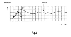
- Fig. 4 shows the speed curve after a command and a load surge through curve a with a PI controller set according to the symmetrical optimum method and through curve b with the speed control method according to the invention.
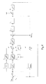
- FIG. 7 An example of a circuit arrangement for carrying out the method according to the invention in an oscillatable drive train is shown in FIG. 7 as a block diagram and is explained in the following: integral behavior is assumed for the mechanical controlled system 22, for the method presented here the required load torque m L is taken out the inverse model 23 of the structure image in FIG. 6.
- the Speed control with subordinate current or torque control consists of blocks 1 to 18.
- a current or torque controller is indicated by 20 and the electrical system is indicated by 21.
- the difference between the specified engine speed setpoint n target and the measured engine speed actual value n actual is formed in a subtractor 1 for the speed deviation ⁇ n, amplified in a proportional element 2 and possibly limited with a limiter 3, in order then to be present as a first input signal a3 to a first summer 17.
- engine speed n M n actual and engine torque m M
- all variables that are difficult to access are determined: spring torque m F , load torque m L and load speed n L .
- the model parameters shown in FIGS. 5 and 6 are determined by design data of the mechanical system. They can also be determined on the drive if necessary, cf. Langhoff, Jürgen / Raatz, Eckart: Regulated DC drives, 1977, Elitera-Verlag, Berlin, p. 129 ff.
- a second subtractor 9 an integral element 10 with the integration time constant T F and a proportional element 11 of the gain factor 1 / k F together form the inverse model 23 of the PI element of the gain k F and the time constant k F T F shown in FIG. 6
- pilot control signal a15 has the same task as the integral component of a PI controller: the subordinate current or
- Torque control loop to specify the setpoint according to the engine load, while the control deviation ⁇ n is virtually zero.
- the function of the control part 6 has already been described in connection with FIG. 1.
- the upper and lower limits of the limiter 5 are opened so that the integrating element 4 can compensate for the control deviation that occurs.
- the output signal a5 of the module 5 is the third input signal of the first summer 17.
- the signal a11 which represents the speed difference between the engine and the inertia mass, is amplified in the proportional element 16 as a vibration-damping signal a16 and fed to the first summer 17 as a fourth input signal.
- the sum of the signals a3, a5, a15, and a16 is possibly limited in a limiter 18.
- the method according to the invention not only achieves fast, overshoot-free speed control, but also advantageously achieves a control accuracy that corresponds to that of a PI controller.
Landscapes
- Engineering & Computer Science (AREA)
- Power Engineering (AREA)
- Control Of Electric Motors In General (AREA)
- Control Of Multiple Motors (AREA)
Applications Claiming Priority (4)
| Application Number | Priority Date | Filing Date | Title |
|---|---|---|---|
| DE19617866 | 1996-04-24 | ||
| DE19617866A DE19617866A1 (de) | 1996-04-24 | 1996-04-24 | Hochdynamische, überschwingfreie Drehzahlregelung von Motoren mit Lastschwungmasse und elastischer Welle |
| DE19617867 | 1996-04-24 | ||
| DE19617867A DE19617867A1 (de) | 1996-04-24 | 1996-04-24 | Hochdynamischer, überschwingfreier Drehzahlregler |
Publications (3)
| Publication Number | Publication Date |
|---|---|
| EP0803970A2 true EP0803970A2 (fr) | 1997-10-29 |
| EP0803970A3 EP0803970A3 (fr) | 1998-04-15 |
| EP0803970B1 EP0803970B1 (fr) | 2000-10-25 |
Family
ID=26025385
Family Applications (1)
| Application Number | Title | Priority Date | Filing Date |
|---|---|---|---|
| EP97400924A Expired - Lifetime EP0803970B1 (fr) | 1996-04-24 | 1997-04-23 | Méthode de la régulation de vitesse exempt de suroscillations pour des moteurs à courant continu et à courant alternatif |
Country Status (2)
| Country | Link |
|---|---|
| EP (1) | EP0803970B1 (fr) |
| DE (1) | DE59702517D1 (fr) |
Family Cites Families (2)
| Publication number | Priority date | Publication date | Assignee | Title |
|---|---|---|---|---|
| DD116359A1 (fr) * | 1974-12-23 | 1975-11-12 | ||
| DE3871074D1 (de) * | 1987-10-26 | 1992-06-17 | Siemens Ag | Verfahren zur erfassung und regelung eines federmoments sowie einer differenzdrehzahl bei rotatorisch angetriebenen zwei-massen-systemen. |
-
1997
- 1997-04-23 EP EP97400924A patent/EP0803970B1/fr not_active Expired - Lifetime
- 1997-04-23 DE DE59702517T patent/DE59702517D1/de not_active Expired - Fee Related
Also Published As
| Publication number | Publication date |
|---|---|
| DE59702517D1 (de) | 2000-11-30 |
| EP0803970A3 (fr) | 1998-04-15 |
| EP0803970B1 (fr) | 2000-10-25 |
Similar Documents
| Publication | Publication Date | Title |
|---|---|---|
| DE69828348T2 (de) | Einrichtung zur Steuerung der Geschwindigkeit von Aufzügen | |
| DE2802224C2 (de) | Schaltungsanordnung zur proportional-integralen Drehzahlregelung einer von einem Elektromotor angetriebenen Arbeitsmaschine mit veränderlicher Belastung | |
| DE3887062T2 (de) | Servosteuerung. | |
| DE69403185T2 (de) | Gerät zum Steuern der Schwingungen eines Motors und Verfahren zur Angleichung des gemessenen Geschwindigkeitswerts eines Motors an einem Geschwindigkeitssollwert | |
| DE4408105C2 (de) | Positionsregler und zugehöriges Verfahren zur Positionsregelung | |
| DE2739220A1 (de) | Verfahren und vorrichtung zur erhoehung der starrheit von servosystemen fuer begrenzte frequenz | |
| DE112010003878T5 (de) | Positionierungssteuervorrichtung | |
| EP1203270B1 (fr) | Procede et dispositif d'amortissement de vibrations torsionnelles d'un moteur a combustion interne | |
| DE69512825T2 (de) | Geschwindigkeitssteuerungsgerät für einen Motor | |
| DE3731983A1 (de) | Verfahren und stellregler zur adapitven stellregelung eines reibungsbehafteten elektro-mechanischen antriebs | |
| DE102014101252B4 (de) | Positionssteuervorrichtung | |
| DE3416496A1 (de) | Verfahren und schaltungsanordnung zum simulieren von pruefstandstraegheitsmomenten | |
| EP0896263B1 (fr) | Procédé et circuit pour déterminer les paramètres optimaux pour contrôle de vitesse de rotation | |
| DE4395770B4 (de) | Verfahren für die Steuerung bzw. Regelung einer harmonisch schwingenden Last | |
| EP1118043B1 (fr) | Procede et circuit pour parametrer automatiquement un circuit de regulation de vitesse numerique rapide | |
| EP0803970B1 (fr) | Méthode de la régulation de vitesse exempt de suroscillations pour des moteurs à courant continu et à courant alternatif | |
| DE68919171T2 (de) | Servo-Steuerungsgerät. | |
| EP1005147A2 (fr) | Méthode et circuit électrique pour déterminer le gain optimal de l'intégrateur d'un régulateur de vitesse | |
| DE1299452B (de) | Stabilisierung von verzoegerungsarmen Regel- oder Steuerstrecken | |
| DE3223786C2 (fr) | ||
| DE19617866A1 (de) | Hochdynamische, überschwingfreie Drehzahlregelung von Motoren mit Lastschwungmasse und elastischer Welle | |
| EP4005076B1 (fr) | Convertisseur de courant à amortissement actif de la tension du circuit intermédiaire | |
| DE10302374B3 (de) | Verfahren zur Erhöhung der Regeldynamik eines mindestens einer Lose und/oder Elastizität aufweisenden Antriebsstranges einer Werkzeug- oder Produktionsmaschine | |
| EP1805818A1 (fr) | Circuit d'excitation hybride | |
| DE19617867A1 (de) | Hochdynamischer, überschwingfreier Drehzahlregler |
Legal Events
| Date | Code | Title | Description |
|---|---|---|---|
| PUAI | Public reference made under article 153(3) epc to a published international application that has entered the european phase |
Free format text: ORIGINAL CODE: 0009012 |
|
| AK | Designated contracting states |
Kind code of ref document: A2 Designated state(s): BE CH DE FR GB LI NL |
|
| PUAL | Search report despatched |
Free format text: ORIGINAL CODE: 0009013 |
|
| AK | Designated contracting states |
Kind code of ref document: A3 Designated state(s): BE CH DE FR GB LI NL |
|
| 17P | Request for examination filed |
Effective date: 19980401 |
|
| RIN1 | Information on inventor provided before grant (corrected) |
Inventor name: DAO HOANG-MINH |
|
| RAP3 | Party data changed (applicant data changed or rights of an application transferred) |
Owner name: ALCATEL |
|
| RAP3 | Party data changed (applicant data changed or rights of an application transferred) |
Owner name: ALCATEL |
|
| GRAG | Despatch of communication of intention to grant |
Free format text: ORIGINAL CODE: EPIDOS AGRA |
|
| 17Q | First examination report despatched |
Effective date: 19990929 |
|
| GRAG | Despatch of communication of intention to grant |
Free format text: ORIGINAL CODE: EPIDOS AGRA |
|
| GRAH | Despatch of communication of intention to grant a patent |
Free format text: ORIGINAL CODE: EPIDOS IGRA |
|
| GRAH | Despatch of communication of intention to grant a patent |
Free format text: ORIGINAL CODE: EPIDOS IGRA |
|
| GRAA | (expected) grant |
Free format text: ORIGINAL CODE: 0009210 |
|
| AK | Designated contracting states |
Kind code of ref document: B1 Designated state(s): BE CH DE FR GB LI NL |
|
| PG25 | Lapsed in a contracting state [announced via postgrant information from national office to epo] |
Ref country code: NL Free format text: LAPSE BECAUSE OF FAILURE TO SUBMIT A TRANSLATION OF THE DESCRIPTION OR TO PAY THE FEE WITHIN THE PRESCRIBED TIME-LIMIT Effective date: 20001025 Ref country code: GB Free format text: LAPSE BECAUSE OF FAILURE TO SUBMIT A TRANSLATION OF THE DESCRIPTION OR TO PAY THE FEE WITHIN THE PRESCRIBED TIME-LIMIT Effective date: 20001025 Ref country code: FR Free format text: LAPSE BECAUSE OF FAILURE TO SUBMIT A TRANSLATION OF THE DESCRIPTION OR TO PAY THE FEE WITHIN THE PRESCRIBED TIME-LIMIT Effective date: 20001025 |
|
| REG | Reference to a national code |
Ref country code: CH Ref legal event code: EP |
|
| REF | Corresponds to: |
Ref document number: 59702517 Country of ref document: DE Date of ref document: 20001130 |
|
| EN | Fr: translation not filed | ||
| NLV1 | Nl: lapsed or annulled due to failure to fulfill the requirements of art. 29p and 29m of the patents act | ||
| GBV | Gb: ep patent (uk) treated as always having been void in accordance with gb section 77(7)/1977 [no translation filed] |
Effective date: 20001025 |
|
| PG25 | Lapsed in a contracting state [announced via postgrant information from national office to epo] |
Ref country code: BE Free format text: LAPSE BECAUSE OF NON-PAYMENT OF DUE FEES Effective date: 20010430 |
|
| PG25 | Lapsed in a contracting state [announced via postgrant information from national office to epo] |
Ref country code: LI Free format text: LAPSE BECAUSE OF NON-PAYMENT OF DUE FEES Effective date: 20010522 Ref country code: CH Free format text: LAPSE BECAUSE OF NON-PAYMENT OF DUE FEES Effective date: 20010522 |
|
| PLBE | No opposition filed within time limit |
Free format text: ORIGINAL CODE: 0009261 |
|
| STAA | Information on the status of an ep patent application or granted ep patent |
Free format text: STATUS: NO OPPOSITION FILED WITHIN TIME LIMIT |
|
| 26N | No opposition filed | ||
| BERE | Be: lapsed |
Owner name: ALCATEL Effective date: 20010430 |
|
| REG | Reference to a national code |
Ref country code: CH Ref legal event code: PL |
|
| PGFP | Annual fee paid to national office [announced via postgrant information from national office to epo] |
Ref country code: DE Payment date: 20030624 Year of fee payment: 7 |
|
| PG25 | Lapsed in a contracting state [announced via postgrant information from national office to epo] |
Ref country code: DE Free format text: LAPSE BECAUSE OF NON-PAYMENT OF DUE FEES Effective date: 20041103 |