EP0803970A2 - Overshootfree speed control method for dc and ac motors - Google Patents
Overshootfree speed control method for dc and ac motors Download PDFInfo
- Publication number
- EP0803970A2 EP0803970A2 EP97400924A EP97400924A EP0803970A2 EP 0803970 A2 EP0803970 A2 EP 0803970A2 EP 97400924 A EP97400924 A EP 97400924A EP 97400924 A EP97400924 A EP 97400924A EP 0803970 A2 EP0803970 A2 EP 0803970A2
- Authority
- EP
- European Patent Office
- Prior art keywords
- speed
- load
- actual
- drive train
- control
- Prior art date
- Legal status (The legal status is an assumption and is not a legal conclusion. Google has not performed a legal analysis and makes no representation as to the accuracy of the status listed.)
- Granted
Links
Images


Classifications
-
- H—ELECTRICITY
- H02—GENERATION; CONVERSION OR DISTRIBUTION OF ELECTRIC POWER
- H02P—CONTROL OR REGULATION OF ELECTRIC MOTORS, ELECTRIC GENERATORS OR DYNAMO-ELECTRIC CONVERTERS; CONTROLLING TRANSFORMERS, REACTORS OR CHOKE COILS
- H02P29/00—Arrangements for regulating or controlling electric motors, appropriate for both AC and DC motors
- H02P29/0016—Control of angular speed of one shaft without controlling the prime mover
Definitions
- the invention relates to a method for overshoot-free speed control of DC and AC motors with subordinate current or torque control.
- Decisive for the control dynamics of a speed control are the rise and fall time of the controlled variable after a speed or a load surge.
- the speed overshoots after a guide impulse and the speed drop after a load impulse cf. Buxbaum, Arne / Schierau, Klaus: Calculation of control loops for drive technology, 4th edition, AEG-Telefunken AG, Berlin, Frankfurt am Main 1980, Figures 11, 12, 177 and 178.
- a PI controller combines the fast reaction of a P controller with the correction of an I controller after a fault.
- the integral component ensures that the control deviation is corrected as the difference between the setpoint and the actual value of the controlled variable. Since the integral component of the PI controller does not permit a rapid change in the control signal, the integration behavior of the integral component is the cause for the overshoot of the control signal and thus also the controlled variable.
- the controller is set according to the symmetrical optimum method, whereby an overshoot range of approx. 40% of the speed jump after a lead impact is accepted, cf. Buxbaum / Schi Lucas, p. 116 ff. If the overshoot is to be smaller, the controller must be set more slowly, and the slower the speed control - i.e. the greater the rise and fall time - the greater the drop in speed after a load surge. If the speed overshoot is undesirable, either a speed surge should be avoided, for example the speed setpoint is led to a ramp function, or a very slow speed control is inevitable. A slowly set speed controller provides a large drop in speed after a load surge, but this is often undesirable.
- the speed controller must be set even more slowly so that the control does not become unstable, cf. Raatz, Eckart: Speed control of a converter-fed DC motor with vibrating mechanics. Techn. Mitt. AEG-Telefunken 60 (1970) 6, pp. 369-372.
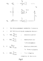
- the entire drive train can be approximated as an elastically coupled two-mass system according to FIG. 5.
- its structural image according to Raatz can be specified as in FIG. 6. 6
- motor torque m M , spring torque m F , load torque m L , motor speed n M and speed n L of the flywheel mass are only the motor speed and motor (active) current, which is a measure of the Torque supplied by the motor is available, while load torque, load speed and spring torque are usually available for direct measurement are inaccessible or a measurement is only possible with great effort.
- the object is to be achieved to design a method of the type mentioned in such a way that overshoot of the speed list value is avoided both in the case of a rigid drive train and in the case of an oscillatable drive train after a sudden change in the speed setpoint, the control dynamics in this process is better than that of a PI controller set according to the symmetrical optimum method.
- the essence of the invention is that the limitation of the output signal of the integral element depending on the state of the speed deviation and the load-compensating feedforward control advantageously prevent the overspeed of the actual speed after a jump in the speed setpoint. At the same time, due to the now easily possible increase in the proportional gain of the speed controller, the drop in speed after a load surge can be kept smaller compared to the known solutions.
- the load-compensating feedforward control is determined from the inverse model, which was developed from the structural diagram according to FIG. 6.
- the determined value a8 corresponds to the load torque acting on the motor.
- a pilot control signal a9 is available to summer 10 as a second input signal.
- the task of the pilot control signal a9 in the steady state of the controlled system corresponds to the integral component of a PI controller: the subordinate current or torque control loop to specify the compensation component according to the load torque, while the control deviation ⁇ n is virtually zero.
- the task of a control part 6 is to influence the limits of a limiter 5, which determines the maximum or minimum output variable of an integrating element 4, depending on the state of the speed deviation ⁇ n: they are controlled smaller with increasing speed deviation ⁇ n.
- the speed deviation is in the quasi-stationary range, ie if l ⁇ nl is less than a certain value
- the output signal a62 and the output signal a65 of a block 65 determine the maximum upper limit of the limiter 5.
- in the dynamic range the signal a 62 becomes zero; this closes the limits of the limiter 5, which suppress the integral part of the speed control.
- the transition from the quasi-stationary area to the dynamic area and vice versa of the curve of the dependent variable a62 is provided with smoothing or at least with a ramp function.
- Blocks 63 to 66 help to avoid the fluttering of the borders.
- Module 63 acts like a two-point switch with hysteresis.
- and a63 0 for
- Block 64 is a timer with a switch-on delay function.
- the value one of the input signal a63 is only present as signal a64 after a delay time T at the output of the module 64. This avoids an unnecessarily frequent switching in the area of the transition phase from the quasi-stationary area to the dynamic area, see curves c and d of FIG. 3.
- the signal a64 is smoothed into the signal signal a65, which multiplied by the signal a62 to signal a66 as the upper limit of the limiter 5.
- the lower limit as signal a67 is formed by negating signal a66 in module 67.
- the upper and lower limits of the limiter 5 are determined as a function of the state of the speed deviation.
- the limits of the limiter 5 are controlled, this suppresses the integral part of the speed control, the value of the signal a5 is zero and thus the overshoot.
- the stability limit depends on the quality of the measured controlled variable and on the sampling time of the control if the control works digitally.
- the stability limit is defined by the smallest possible integration time constant T l, min at a certain gain factor k or by the greatest possible gain factor k max at a certain integration time constant T l without the speed starting to oscillate.
- the limit gain kmax will be smaller the smaller the integration time constant T l is set.
- the integral component is suppressed in the dynamic state, which corresponds to an infinitely high integration time constant, which allows the limit gain kmax to be increased without the control system becoming unstable.
- the increase in gain has an advantageous effect on the rise and fall time as well as on the speed change after a load change, ie there is only a smaller drop in speed after a load surge.
- the output signal a5 of the module 5 is the third input signal of the summer 10.
- the sum of a3, a5 and a9 may be restricted.
- Fig. 4 shows the speed curve after a command and a load surge through curve a with a PI controller set according to the symmetrical optimum method and through curve b with the speed control method according to the invention.
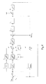
- FIG. 7 An example of a circuit arrangement for carrying out the method according to the invention in an oscillatable drive train is shown in FIG. 7 as a block diagram and is explained in the following: integral behavior is assumed for the mechanical controlled system 22, for the method presented here the required load torque m L is taken out the inverse model 23 of the structure image in FIG. 6.
- the Speed control with subordinate current or torque control consists of blocks 1 to 18.
- a current or torque controller is indicated by 20 and the electrical system is indicated by 21.
- the difference between the specified engine speed setpoint n target and the measured engine speed actual value n actual is formed in a subtractor 1 for the speed deviation ⁇ n, amplified in a proportional element 2 and possibly limited with a limiter 3, in order then to be present as a first input signal a3 to a first summer 17.
- engine speed n M n actual and engine torque m M
- all variables that are difficult to access are determined: spring torque m F , load torque m L and load speed n L .
- the model parameters shown in FIGS. 5 and 6 are determined by design data of the mechanical system. They can also be determined on the drive if necessary, cf. Langhoff, Jürgen / Raatz, Eckart: Regulated DC drives, 1977, Elitera-Verlag, Berlin, p. 129 ff.
- a second subtractor 9 an integral element 10 with the integration time constant T F and a proportional element 11 of the gain factor 1 / k F together form the inverse model 23 of the PI element of the gain k F and the time constant k F T F shown in FIG. 6
- pilot control signal a15 has the same task as the integral component of a PI controller: the subordinate current or
- Torque control loop to specify the setpoint according to the engine load, while the control deviation ⁇ n is virtually zero.
- the function of the control part 6 has already been described in connection with FIG. 1.
- the upper and lower limits of the limiter 5 are opened so that the integrating element 4 can compensate for the control deviation that occurs.
- the output signal a5 of the module 5 is the third input signal of the first summer 17.
- the signal a11 which represents the speed difference between the engine and the inertia mass, is amplified in the proportional element 16 as a vibration-damping signal a16 and fed to the first summer 17 as a fourth input signal.
- the sum of the signals a3, a5, a15, and a16 is possibly limited in a limiter 18.
- the method according to the invention not only achieves fast, overshoot-free speed control, but also advantageously achieves a control accuracy that corresponds to that of a PI controller.
Abstract
Description
Die Erfindung bezieht sich auf ein Verfahren zur überschwingfreien Drehzahlregelung von Gleich- und Drehstrommotoren mit unterlagerter Strom- bzw. Drehmomentenregelung.The invention relates to a method for overshoot-free speed control of DC and AC motors with subordinate current or torque control.
Maßgebend für die Regeldynamik einer Drehzahlregelung sind die An- und Ausregelzeit der Regelgröße nach einem Drehzahl- bzw. einem Laststoß. Zu der Regelgüte kommen bei einem herkömmlichen Pl-Regler noch das Überschwingen der Drehzahl nach einem Führungsstoß sowie der Drehzahleinbruch nach einem Laststoß, vgl. Buxbaum, Arne / Schierau, Klaus: Berechnung von Regelkreisen der Antriebstechnik, 4. Aufl., AEG-Telefunken AG, Berlin, Frankfurt am Main 1980, Bilder 11, 12, 177 und 178.Decisive for the control dynamics of a speed control are the rise and fall time of the controlled variable after a speed or a load surge. In addition to the control quality of a conventional PI controller, the speed overshoots after a guide impulse and the speed drop after a load impulse, cf. Buxbaum, Arne / Schierau, Klaus: Calculation of control loops for drive technology, 4th edition, AEG-Telefunken AG, Berlin, Frankfurt am Main 1980, Figures 11, 12, 177 and 178.
Ein Pl-Regler kombiniert bekanntlich die schnelle Reaktion eines P-Reglers mit dem Ausregeln eines I-Reglers nach einer Störung. Der Integralanteil sorgt für die Ausregelung der Regelabweichung als Differenz zwischen dem Soll- und dem Istwert der Regelgröße. Da der Integralanteil des Pl-Reglers eine schnelle Änderung des Stellsignals nicht zuläßt, ist das Integrationsverhalten des Integralanteils Ursache für das Überschwingen des Stellsignals und damit auch der Regelgröße.As is known, a PI controller combines the fast reaction of a P controller with the correction of an I controller after a fault. The integral component ensures that the control deviation is corrected as the difference between the setpoint and the actual value of the controlled variable. Since the integral component of the PI controller does not permit a rapid change in the control signal, the integration behavior of the integral component is the cause for the overshoot of the control signal and thus also the controlled variable.
Um ein ausgewogenes Verhältnis zwischen der Überschwingweite nach einem Führungsstoß und dem Drehzahleinbruch nach einem Laststoß zu erhalten, wird der Regler nach der Methode des symmetrischen Optimums eingestellt, dabei wird eine Überschwingweite von ca. 40% des Drehzahlsprunges nach einem Führungsstoß in Kauf genommen, vgl. Buxbaum / Schierau, S. 116 ff. Soll das Überschwingen kleiner sein, muß der Regler langsamer eingestellt werden, und je langsamer die Drehzahlregelung ist - also um so größer die An- und Ausregelzeit - um so größer ist auch der Drehzahleinbruch nach einem Laststoß. Ist ein Überschwingen der Drehzahl unerwünscht, so ist entweder ein Drehzahlstoß zu vermeiden, beispielsweise wird der Drehzahlsollwert an eine Rampenfunktion geführt, oder eine sehr langsame Drehzahlregelung ist unausweichlich. Ein langsam eingestellter Drehzahlregler liefert nach einem Laststoß einen großen Drehzahleinbruch, der aber oft unerwünscht ist.In order to obtain a balanced relationship between the overshoot after a lead impact and the drop in speed after a load impact, the controller is set according to the symmetrical optimum method, whereby an overshoot range of approx. 40% of the speed jump after a lead impact is accepted, cf. Buxbaum / Schierau, p. 116 ff. If the overshoot is to be smaller, the controller must be set more slowly, and the slower the speed control - i.e. the greater the rise and fall time - the greater the drop in speed after a load surge. If the speed overshoot is undesirable, either a speed surge should be avoided, for example the speed setpoint is led to a ramp function, or a very slow speed control is inevitable. A slowly set speed controller provides a large drop in speed after a load surge, but this is often undesirable.
Wenn die Welle einschließlich Kupplung und Getriebe zwischen Motor und Last nicht ausreichend starr ist, d.h. wenn der Antriebsstrang ein schwach gedämpftes schwingungsfähiges Mehrmassensystem bildet, ist der Drehzahlregler noch langsamer einzustellen, damit die Regelung nicht instabil wird, vgl. Raatz, Eckart: Drehzahlregelung eines stromrichtergespeisten Gleichstrommotors mit schwingungsfähiger Mechanik. Techn. Mitt. AEG-Telefunken 60 (1970) 6, S. 369-372.If the shaft, including the coupling and gearbox, is not sufficiently rigid between the motor and the load, i.e. If the drive train forms a weakly damped, vibrating multi-mass system, the speed controller must be set even more slowly so that the control does not become unstable, cf. Raatz, Eckart: Speed control of a converter-fed DC motor with vibrating mechanics. Techn. Mitt. AEG-Telefunken 60 (1970) 6, pp. 369-372.
In vielen Fällen kann der gesamte Antriebsstrang als ein elastisch gekoppeltes Zweimassensystem gemäß Fig. 5 angenähert werden. Im Fall eines schwingungsfähigen Zweimassensystems kann dessen Strukturbild nach Raatz wie in Fig. 6 angegeben werden. Von den im Strukturbild gemäß Fig. 6 vorkommenden Größen Motordrehmoment mM, Federdrehmoment mF, Lastdrehmoment mL, Motordrehzahl nM und Drehzahl nL der Lastschwungmasse stehen den regelungstechnischen Zwecken lediglich Motordrehzahl und Motor (Wirk-)strom, der ein Maß für das vom Motor gelieferte Drehmoment ist, zur Verfügung, während Lastdrehmoment, Lastdrehzahl und Federdrehmoment für eine direkte Messung in der Regel unzugänglich sind bzw. eine Messung nur mit sehr großem Aufwand möglich ist.In many cases, the entire drive train can be approximated as an elastically coupled two-mass system according to FIG. 5. In the case of an oscillatory two-mass system, its structural image according to Raatz can be specified as in FIG. 6. 6, motor torque m M , spring torque m F , load torque m L , motor speed n M and speed n L of the flywheel mass are only the motor speed and motor (active) current, which is a measure of the Torque supplied by the motor is available, while load torque, load speed and spring torque are usually available for direct measurement are inaccessible or a measurement is only possible with great effort.
Mit der Erfindung soll nun die Aufgabe gelöst werden, ein Verfahren der eingangs genannten Art so auszugestalten, daß ein Überschwingen des Drehzahllistwertes sowohl bei einem starren Antriebsstrang als auch bei einem schwingfähigen Antriebsstrang nach einer sprungförmigen Änderung des Drehzahlsollwertes vermieden wird, wobei die Regeldynamik bei diesem Verfahren besser ist als die eines nach der Methode des symmetrischen Optimums eingestellten Pl-Reglers.With the invention, the object is to be achieved to design a method of the type mentioned in such a way that overshoot of the speed list value is avoided both in the case of a rigid drive train and in the case of an oscillatable drive train after a sudden change in the speed setpoint, the control dynamics in this process is better than that of a PI controller set according to the symmetrical optimum method.
Diese Aufgabe wird mit dem im ersten Patentanspruch beschriebenen Verfahren gelöst. In den Patentansprüchen zwei bis fünf werden vorteilhafte Ausgestaltungen und Varianten der Erfindung angegeben.This object is achieved with the method described in the first claim. Advantageous refinements and variants of the invention are specified in patent claims two to five.
Das Wesen der Erfindung besteht darin, daß durch die vom Zustand der Drehzahlabweichung anhängige Begrenzung des Ausgangssignals des Integralgliedes und durch die lastkompensierende Vorsteuerung vorteilhafterweise das Überschwingen des Drehzahlistwertes nach einem Sprung des Drehzahlsollwertes vermieden wird. Gleichzeitig kann durch die nun ohne weiteres mögliche Erhöhung der Proportionalverstärkung des Drehzahlreglers der Drehzahleinbruch nach einem Laststoß gegenüber den bekannten Lösungen kleiner gehalten werden.The essence of the invention is that the limitation of the output signal of the integral element depending on the state of the speed deviation and the load-compensating feedforward control advantageously prevent the overspeed of the actual speed after a jump in the speed setpoint. At the same time, due to the now easily possible increase in the proportional gain of the speed controller, the drop in speed after a load surge can be kept smaller compared to the known solutions.
Bei einem schwingfähigen Antriebsstrang wird die lastkompensierende Vorsteuerung aus dem Inverse-Modell, das aus dem Strukturbild gemäß Fig. 6 entwickelt wurde, ermittelt.In the case of an oscillatable drive train, the load-compensating feedforward control is determined from the inverse model, which was developed from the structural diagram according to FIG. 6.
Die Erfindung wird nunmehr an einem Ausführungsbeispiel erläutert. in der dazugehörigen Zeichnung zeigen:
- Fig. 1
- ein Blockschaltbild einer Schaltungsanordnung zur Durchführung des Verfahrens bei einem starren Antriebsstrang,
- Fig. 2
- ein detailliertes Blockschaltbild des
Regelungsteil 6 in Fig. 1, - Fig. 3
- a, b, c, d funktionale Darstellungen der in Fig. 2 eingezeichneten Signale,
- Fig. 4
- einen Drehzahlverlauf als Funktion der Zeit gemäß dem Stand der Technik (a) und gemäß der Erfindung (b) bei einem starren Antriebsstrang,
- Fig. 5
- eine Darstellung eines elastisch gekoppelten Zweimassensystems nach dem Stand der Technik,
- Fig. 6
- ein Strukturbild des Zweimassensystems nach dem Stand der Technik,
- Fig. 7
- ein Blockschaltbild einer Schaltungsanordnung zur Durchführung des Verfahrens bei einem schwingfähigen Antriebsstrang und
- Fig. 8
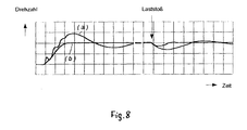
- einen Drehzahlverlauf als Funktion der Zeit gemäß dem Stand der Technik (a) und gemäß der Erfindung (b) bei einem schwingfähigen Antriebsstrang.
- Fig. 1
- 2 shows a block diagram of a circuit arrangement for carrying out the method in the case of a rigid drive train,
- Fig. 2
- 2 shows a detailed block diagram of the
control part 6 in FIG. 1, - Fig. 3
- a, b, c, d functional representations of the signals shown in FIG. 2,
- Fig. 4
- a speed curve as a function of time according to the prior art (a) and according to the invention (b) with a rigid drive train,
- Fig. 5
- a representation of an elastically coupled two-mass system according to the prior art,
- Fig. 6
- a structural diagram of the two-mass system according to the prior art,
- Fig. 7
- a block diagram of a circuit arrangement for performing the method in an oscillatable drive train and
- Fig. 8
- a speed curve as a function of time according to the prior art (a) and according to the invention (b) with an oscillatable drive train.
Gemäß Fig. 1 besteht die Schaltungsanordnung für die Drehzahlregelung mit unterlagerter Strom- bzw. Drehmomentenregelung bei einem starren Antriebsstrang aus den Bausteinen 1 bis 11. Ein Strom- bzw. Drehmomentenregler ist mit 13 und die elektrische Strecke ist mit 14 bezeichnet. Für die mechanische Regelstrecke 15 wird Integralverhalten angenommen. Die Differenz zwischen dem vorgegebenen Drehzahlsollwert nSoll und dem gemessenen Drehzahlistwert nlst, wird in einem ersten Subtrahierer 1 zur Drehzahlabweichung Δn gebildet, in einem Proportionalglied 2 verstärkt und mit einem Begrenzer 3 gegebenenfalls eingegrenzt, um dann als erstes Eingangssignal a3 einem Summierer 10 vorzuliegen. Der Drehzahlistwert nlst wird in einem Differenzierglied 7 differenziert und dann in einem zweiten Subtrahierer 8 von der Rückführung der unterlagerten Strom- bzw. Drehmomentenregelung abgezogen, Signal a8.1 there is the circuit arrangement for the speed control with subordinate current b between . Torque control in the case of a rigid drive train from
Bei entsprechender Parametrierung des Differenziergliedes 7, gemäß der mechanischen Strecke 15, entspricht der ermittelte Wert a8 dem am Motor angreifenden Lastmoment. Nach der Glättung in einem Tiefpaßglied 9 steht ein Vorsteuerungssignal a9 als zweites Eingangssignal dem Summierer 10 zur Verfügung. Die Aufgabe des Vorsteuerungssignals a9 im stationären Zustand der Regelstrecke entspricht dem Integralanteil eines Pl-Reglers: dem unterlagerten Strom- bzw. Drehmomentenregelkreis den Kompensationsanteil entsprechend dem Lastmoment vorzugeben, während die Regelabweichung Δn quasi Null ist.With appropriate parameterization of the differentiating
Die Aufgabe eines Regelungsteils 6 ist es, in Abhängigkeit vom Zustand der Drehzahlabweichung Δn die Grenzen eines Begrenzers 5, welcher die maximale bzw. minimale Ausgangsgröße eines Integriergliedes 4 determiniert, zu beeinflussen: sie werden mit zunehmender Drehzahlabweichung Δn kleiner gesteuert.The task of a
In einer Realisierungsvariante der Schaltung ist es auch möglich, den Ausgang des Proportionalgliedes 2 auf den Eingang des Integriergliedes 4 zurückzuführen.In an implementation variant of the circuit, it is also possible to trace the output of the
Fig. 2 stellt eine Lösungsmöglichkeit zur symmetrischen Steuerung der oberen und unteren Grenze des Begrenzers 5 dar: der besseren Operationalisierung halber wird in einem Baustein 61 die Drehzahlabweichung Δn in ihren Betrag lΔnl umgeformt, dieser liegt dann am Eingang von Bausteinen 62 und 63 vor. Im Baustein 62 wird in Abhängigkeit vom Betrag der Drehzahlabweichung lΔnl ein Ausgangssignal a62 entsprechend dem Kurvenverlauf a der Fig. 3 gebildet: liegt die Drehzahlabweichung im quasi-stationären Bereich vor, d.h. wenn lΔnl kleiner als ein bestimmter Wert |Δn∗| wird, der den gesamten Bereich von |Δn| in einen quasi-stationären und einen dynamischen Bereich unterteilt, determinieren das Ausgangssignal a62 und das Ausgangssignal a65 eines Bausteins 65 die maximale obere Grenze des Begrenzers 5. Liegt dagegen |Δn| im dynamischen Bereich, wird das Signal a 62 Null; dadurch werden die Grenzen des Begrenzers 5 geschlosssen, die eine Unterdrückung des Integralanteils der Drehzahlregelung bewirken.2 shows a possible solution for the symmetrical control of the upper and lower limits of the limiter 5: for the sake of better operationalization, the speed deviation Δn is converted into its amount lΔnl in a
Um eine abrupte Auf- und Zusteuerung der Grenzen zu vermeiden, wird der Übergang vom quasi-stationären Bereich zum dynamischen Bereich und umgekehrt des Kurvenverlaufs der abhängigen Variablen a62 mit Verschliffen oder zumindest mit einer Rampenfunktion versehen. Bausteine 63 bis 66 helfen, das Flattern der Grenzen zu vermeiden.In order to avoid an abrupt opening and closing of the limits, the transition from the quasi-stationary area to the dynamic area and vice versa of the curve of the dependent variable a62 is provided with smoothing or at least with a ramp function.
Der Baustein 63 fungiert wie ein Zweipunktschalter mit Hysterese. Das Ausgangssignal ist![]()
![]()
![]()
![]()
Das Hin- und Herschalten um den Schaltpunkt |Δn∗| wird durch den Einbau einer Hysterese um denselben vermieden. Der Baustein 64 ist eine Zeitglied mit einer Einschaltverzögerungsfunktion. Der Wert eins des Eingangssignals a63 liegt erst nach einer Verzögerungszeit T am Ausgang des Bausteins 64 als Signal a64 vor. Dadurch wird ein unnötig häufiges Umschalten im Bereich der Übergangsphase vom quasi-stationären Bereich zum dynamischen Bereich vermieden siehe Kurven c und d der Fig. 3. Im Tiefpaß 65 beispielsweise als Verzögerungsglied erster Ordnung realisiert, wird das Signal a64 zum Signal Signal a65 geglättet, das multiplikativ mit dem Signal a62 zum Signal a66 als obere Grenze des Begrenzers 5 gebildet wird. Die untere Grenze als Signal a67 wird durch Negation des Signals a66 im Baustein 67 gebildet.Switching back and forth around the switching point | Δn ∗ | is avoided by installing a hysteresis around it.
Im Regelungsteil 6 werden also die obere und die untere Grenze des Begrenzers 5 in Abhängigkeit vom Zustand der Drehzahlabweichung ermittelt. Im dynamischen Zustand, d.h. wenn die Drehzahlabweichung außerhalb einer bestimmten Bandbreite liegt, werden die Grenzen des Begrenzers 5 zugesteuert, dadurch wird der Integralanteil der Drehzahlregelung unterdrückt, der Wert des Signals a5 ist Null und damit auch das Überschwingen.In the
Beim Pl-Regler hängt die Stabilitätsgrenze von der Güte der gemessenen Regelgröße und von der Abtastzeit der Regelung ab, wenn die Regelung digital arbeitet. Die Stabilitätsgrenze ist definiert durch die kleinstmögliche Integrationszeitkonstante Tl,min bei einem bestimmten Verstärkungsfaktor k bzw. durch den größtmöglichen Verstärkungsfaktor kmax bei einer bestimmten Integrationszeitkonstante Tl, ohne daß die Drehzahl anfängt zu schwingen. Dabei wird die Grenzverstärkung kmax umso kleiner sein, je kleiner die Integrationszeitkonstante Tl eingestellt ist. Bei dem hier vorgestellten Drehzahlregelungsverfahren wird der Integralanteil im dynamischen Zustand unterdrückt, das entspricht einer unendlich hohen Integrationszeitkonstanten, die eine Erhöhung der Grenzverstärkung kmax erlaubt, ohne daß das Regelsystem instabil wird. Die Verstärkungserhöhung wirkt sich vorteilhaft aus auf die An- und Ausregelzeit sowie auf die Drehzahländerung nach einer Laständerung, d.h. es entsteht nur ein kleinerer Drehzahleinbruch nach einem Laststoß.In the case of the PI controller, the stability limit depends on the quality of the measured controlled variable and on the sampling time of the control if the control works digitally. The stability limit is defined by the smallest possible integration time constant T l, min at a certain gain factor k or by the greatest possible gain factor k max at a certain integration time constant T l without the speed starting to oscillate. The limit gain kmax will be smaller the smaller the integration time constant T l is set. In the speed control method presented here, the integral component is suppressed in the dynamic state, which corresponds to an infinitely high integration time constant, which allows the limit gain kmax to be increased without the control system becoming unstable. The increase in gain has an advantageous effect on the rise and fall time as well as on the speed change after a load change, ie there is only a smaller drop in speed after a load surge.
Im quasi-stationären Zustand, wenn die Drehzahlabweichung innerhalb einer bestimmten Bandbreite liegt, werden die obere und die untere Grenzwert des Begrenzers 5 geöffnet, so daß das Integralglied 4 die auftretende Regelabweichung ausregeln kann. Das Ausgangssignal a5 des Bausteins 5 ist das dritte Eingangssignal des Summierers 10. In einem Begrenzer 11 werden die Summe von a3, a5 und a9 gegebenenfalls eingeschränkt.In the quasi-steady state, when the speed deviation lies within a certain bandwidth, the upper and lower limit values of the
Fig. 4 zeigt den Drehzahlverlauf nach einem Führungs- und einem Laststoß durch Kurve a mit einem nach der Methode des symmetrischen Optimums eingestellten Pl-Regler und durch Kurve b mit dem Drehzahlregelungsverfahren nach der Erfindung.Fig. 4 shows the speed curve after a command and a load surge through curve a with a PI controller set according to the symmetrical optimum method and through curve b with the speed control method according to the invention.
Ein Beispiel einer Schaltungsanordnung zur Durchführung des Verfahrens nach der Erfindung bei einem schwingfähigen Antriebsstrang ist in Fig. 7 als Blockschaltbild dargestellt und wird im folgenden erläutert: für die mechanische Regelstrecke 22 wird Integralverhalten angenommen, für das hier vorgestellte Verfahren wird das benötigte Lastdrehmoment mL aus dem Inverse-Modell 23 des Strukturbildes in Fig. 6 gewonnen. Die Drehzahlregelung mit unterlagerter Strom- bzw. Drehmomentenregelung besteht aus den Bausteinen 1 bis 18. Ein Strom- bzw. Drehmomentenregler ist mit 20 und die elektrische Strecke ist mit 21 bezeichnet. Die Differenz zwischen dem vorgegebenen Motordrehzahlsollwert nSoll und dem gemessenen Motordrehzahlistwert nlst wird in einem Subtrahierer 1 zur Drehzahlabweichung Δn gebildet, in einem Proportionalglied 2 verstärkt und mit einem Begrenzer 3 gegebenenfalls eingegrenzt, um dann als erstes Eingangssignal a3 einem ersten Summierer 17 vorzuliegen. Mit Hilfe des Inverse-Modells 23 des mechanischen Zweimassensystems, Bausteine 7 bis 14, werden aus den Regelgrößen Motordrehzahl nM = nlst, und Motordrehmoment mM alle der Messung schwer zugänglichen Größen ermittelt: Federdrehmoment mF, Lastdrehmoment mL und Lastdrehzahl nL. Die in Fig. 5 und 6 dargestellten Modellparameter werden durch Konstruktionsdaten des mechanischen Systems determiniert, sie können auch, falls erforderlich, am Antrieb ermittelt werden, vgl. Langhoff, Jürgen / Raatz, Eckart: Geregelte Gleichstromantriebe, 1977, Elitera-Verlag, Berlin, S. 129 ff. Der Motordrehzahlistwert nM wird in einem ersten Differenzierglied 7 der Differentiationszeitkonstanten TM zum Signal a7 = mM - mF differenziert. In einem ersten Subtrahierer 8 wird das Federdrehmoment mF aus der Differenz zwischen der Rückführung a21 = mM der unterlagerten Strom- bzw. Drehmomentenregelung und dem Signal a7 als Ausgangssignal a8 gebildet. Ein zweiter Subtrahierer 9, ein Integralglied 10 mit der Integrationszeitkonstanten TF und ein Proportionalglied 11 des Verstärkungsfaktors 1/kF stellen zusammen das Inverse-Modell 23 des in Fig. 6 gezeichneten Pl-Gliedes der Verstärkung kF und der Zeitkonstanten kF TF dar. Das Ausgangssignal a11 des Proportionalgiedes 11 gibt die Differenz der Motordrehzahl nM zum Signal a12 = -nL gebildet, diese wird dann in einem zweiten Differenzierglied 13 der Differentiationszeitkonstanten TL zum Signal a13 = mL - mF umgeformt. Die in einem zweiten Summierer 14 gebildete Summe der Signale a13 und a8 = mF liefert das Lastdrehmoment mL als Signal a14, das nach der Glättung in einem Tiefpaß 15 als Vorsteuerungssignal a15 dem ersten Summierer 17 zur Verfügung steht. Im stationären Zustand hat das Vorsteuerungssignal a15 die gleiche Aufgabe wie der Integralanteil eines Pl-Reglers: dem unterlagerten Strom- bzw.An example of a circuit arrangement for carrying out the method according to the invention in an oscillatable drive train is shown in FIG. 7 as a block diagram and is explained in the following: integral behavior is assumed for the mechanical controlled
Drehmomentenregelkreis den Sollwert gemäß der Motorbelastung vorzugeben, während die Regelabweichung Δn quasi Null ist.Torque control loop to specify the setpoint according to the engine load, while the control deviation Δn is virtually zero.
Die Funktion des Regelungsteils 6 wurde bereits im Zusammenhang mit Fig. 1 beschrieben. Im quasi-stationären Zustand, wenn die Drehzahlabweichung innerhalb einer bestimmten Bandbreite liegt, werden die obere und untere Grenze des Begrenzers 5 geöffnet, so daß das Integrierglied 4 die auftretende Regelabweichung ausregeln kann. Das Ausgangssignal a5 des Bausteins 5 ist das dritte Eingangssignal des ersten Summierers 17.The function of the
Bei hinreichend kurzer Abtastzeit der digitalen Drehzahlregelung wird das Signal a11, das den Drehzahlunterschied zwischen dem Motor und der Schwung masse wiedergibt, im Proportianalglied 16 als schwingungsdämpfendes Signal a16 verstärkt und dem ersten Summierer 17 als viertes Eingangssignal zugeführt.With a sufficiently short sampling time of the digital speed control, the signal a11, which represents the speed difference between the engine and the inertia mass, is amplified in the
In einem Begrenzer 18 wird die Summe der Signale a3, a5, a15, und a16 gegebenenfalls eingeschränkt.The sum of the signals a3, a5, a15, and a16 is possibly limited in a
Fig. 8 zeigt den Drehzahlverlauf nach einem Führungs- und einem Laststoß durch Kurve a mit einem nach der Methode des symmetrischen Optimums eingestellten Pl-Regler und durch Kurve b mit dem Drehzahlregelungsverfahren nach der Erfindung.8 shows the speed curve after a command and a load surge through curve a with a PI controller set according to the symmetrical optimum method and through curve b with the speed control method according to the invention.
Mit dem erfindungsgemäßen Verfahren wird nicht nur eine schnelle, überschwingfreie Drehzahlregelung erreicht, sondern vorteilhafterweise auch eine Regelgenauigkeit erzielt, die der eines Pl-Reglers entspricht.The method according to the invention not only achieves fast, overshoot-free speed control, but also advantageously achieves a control accuracy that corresponds to that of a PI controller.
Claims (5)
dadurch gekennzeichnet, daß eine Abweichung des Drehzahlistwerkes (nlst) vom Drehzahlsollwert (nSoll) durch ein Proportionalglied (2) unmittelbar korrigiert wird, daß das angreifende Lastdrehmoment durch ein lastabhängiges Vorsteuerungssignal (a9, a15) kompensiert wird und daß eine Drehzahlabweichung (Δn) durch ein Integrierglied (4) ausgeregelt wird, dessen maximale Ausgangsgröße (a5) vom Zustand der Drehzahlabweichung (Δn) gesteuert wird, wobei bei einem schwingfähigen Antriebsstrang, der wie ein elastisch gekoppeltes schwingfähiges Zweimassensystem wirkt, die Größen Lastdrehzahl (nL) und Lastdrehmoment (mL) mit Hilfe eines Inverse-Modells (23) des mechanischen Antriebsstranges ermittelt werden.Method for overshoot-free speed control of direct current motors and three-phase motors with subordinate current control or torque control in a rigid drive train or in a drive train capable of oscillation,
characterized in that a deviation of the actual speed (n actual ) from the speed setpoint (n desired ) is corrected directly by a proportional element (2), that the acting load torque is compensated by a load-dependent pilot control signal (a9, a15) and that a speed deviation (Δn) is compensated by an integrating element (4), the maximum output variable (a5) of which is controlled by the state of the speed deviation (Δn), with the variables load speed (n L ) and load torque (n) for an oscillatable drive train that acts like an elastically coupled oscillatable two-mass system. m L ) can be determined using an inverse model (23) of the mechanical drive train.
Applications Claiming Priority (4)
| Application Number | Priority Date | Filing Date | Title |
|---|---|---|---|
| DE19617866 | 1996-04-24 | ||
| DE19617867 | 1996-04-24 | ||
| DE19617866A DE19617866A1 (en) | 1996-04-24 | 1996-04-24 | Speed regulation method for DC and AC electric motors |
| DE19617867A DE19617867A1 (en) | 1996-04-24 | 1996-04-24 | Speed regulation method for DC and AC electric motors |
Publications (3)
| Publication Number | Publication Date |
|---|---|
| EP0803970A2 true EP0803970A2 (en) | 1997-10-29 |
| EP0803970A3 EP0803970A3 (en) | 1998-04-15 |
| EP0803970B1 EP0803970B1 (en) | 2000-10-25 |
Family
ID=26025385
Family Applications (1)
| Application Number | Title | Priority Date | Filing Date |
|---|---|---|---|
| EP97400924A Expired - Lifetime EP0803970B1 (en) | 1996-04-24 | 1997-04-23 | Overshootfree speed control method for dc and ac motors |
Country Status (2)
| Country | Link |
|---|---|
| EP (1) | EP0803970B1 (en) |
| DE (1) | DE59702517D1 (en) |
Citations (2)
| Publication number | Priority date | Publication date | Assignee | Title |
|---|---|---|---|---|
| DD116359A1 (en) * | 1974-12-23 | 1975-11-12 | ||
| EP0313928A1 (en) * | 1987-10-26 | 1989-05-03 | Siemens Aktiengesellschaft | Detection and control method for a moment of torsion and the speed difference of a rotational two-mass system |
-
1997
- 1997-04-23 EP EP97400924A patent/EP0803970B1/en not_active Expired - Lifetime
- 1997-04-23 DE DE59702517T patent/DE59702517D1/en not_active Expired - Fee Related
Patent Citations (2)
| Publication number | Priority date | Publication date | Assignee | Title |
|---|---|---|---|---|
| DD116359A1 (en) * | 1974-12-23 | 1975-11-12 | ||
| EP0313928A1 (en) * | 1987-10-26 | 1989-05-03 | Siemens Aktiengesellschaft | Detection and control method for a moment of torsion and the speed difference of a rotational two-mass system |
Non-Patent Citations (1)
| Title |
|---|
| A. BUXBAUM, K. SCHIERAU: "Berechnung von Regelkreisen der Antriebstechnik" AEG-TELEFUNKEN HANDB]CHER, Bd. 16, 1980, Seiten 16-20, 116-119, 153-168, XP002055693 * |
Also Published As
| Publication number | Publication date |
|---|---|
| EP0803970A3 (en) | 1998-04-15 |
| DE59702517D1 (en) | 2000-11-30 |
| EP0803970B1 (en) | 2000-10-25 |
Similar Documents
| Publication | Publication Date | Title |
|---|---|---|
| DE2802224C2 (en) | Circuit arrangement for proportional-integral speed control of a work machine driven by an electric motor with variable load | |
| DE69828348T2 (en) | Device for controlling the speed of elevators | |
| DE2739220A1 (en) | METHOD AND DEVICE FOR INCREASING THE RIGIDITY OF SERVOSYSTEMS FOR LIMITED FREQUENCY | |
| DE4408105C2 (en) | Position controller and associated method for position control | |
| EP1203270B1 (en) | Method and device for reducing torsional vibrations in an internal combustion engine | |
| DE3416496C2 (en) | ||
| EP0896263A2 (en) | Method and circuit for determining optimal control parameters for rotational speed control | |
| DE102015114458A1 (en) | POWER CONTROL DEVICE | |
| DE4129539A1 (en) | METHOD AND DEVICE FOR REGULATING THE SPEED OF AN ELECTRIC MOTOR | |
| DE3437324A1 (en) | METHOD AND DEVICE FOR REGULATING THE IDLE SPEED IN INTERNAL COMBUSTION ENGINES | |
| EP1005147B1 (en) | Method and electronic circuit for determination of the optimal integrator gain for a speed controller | |
| EP0803970B1 (en) | Overshootfree speed control method for dc and ac motors | |
| EP2100196A1 (en) | Method for the adaptation of the control parameters of a drive controller to changed operating conditions | |
| DE1299452B (en) | Stabilization of low-delay regulation or control lines | |
| DE19617866A1 (en) | Speed regulation method for DC and AC electric motors | |
| DE10302374B3 (en) | Method for adjusting the motor speed of a machine tool to take up any slack in the driven load has tachogenerators at the motor output and load input to establish the speed difference | |
| DE3223786C2 (en) | ||
| DE19617867A1 (en) | Speed regulation method for DC and AC electric motors | |
| EP3144754A1 (en) | Damping of load swinging without additional measurement means on the load side | |
| EP0797133A1 (en) | Optimal torsional control of an electrical speed controlled drive, characterised by rotation-elastic mechanical properties, using a PI-controller | |
| DE10340400B4 (en) | Method and device for damping low-frequency load oscillations in a regulated drive | |
| DE3036658A1 (en) | DC machine drive rotation regulation control - has regulator receiving armature current of machine drive motor via multiplier | |
| DE4423776C2 (en) | Vibration suppression method for drive controls | |
| EP1193577B1 (en) | Method for filtering a signal with derivative action | |
| DD301432A7 (en) | METHOD FOR PARAMETER-OPTIMAL ADJUSTMENT OF A PI-REGULATOR USED BY A STRUCTURAL-IMPROPER ADJUSTMENT OF THE REGULATOR TO THE CONTROL RANGE FOR TRANSMISSION-LOADED MECHANICAL ACTUATORS |
Legal Events
| Date | Code | Title | Description |
|---|---|---|---|
| PUAI | Public reference made under article 153(3) epc to a published international application that has entered the european phase |
Free format text: ORIGINAL CODE: 0009012 |
|
| AK | Designated contracting states |
Kind code of ref document: A2 Designated state(s): BE CH DE FR GB LI NL |
|
| PUAL | Search report despatched |
Free format text: ORIGINAL CODE: 0009013 |
|
| AK | Designated contracting states |
Kind code of ref document: A3 Designated state(s): BE CH DE FR GB LI NL |
|
| 17P | Request for examination filed |
Effective date: 19980401 |
|
| RIN1 | Information on inventor provided before grant (corrected) |
Inventor name: DAO HOANG-MINH |
|
| RAP3 | Party data changed (applicant data changed or rights of an application transferred) |
Owner name: ALCATEL |
|
| RAP3 | Party data changed (applicant data changed or rights of an application transferred) |
Owner name: ALCATEL |
|
| GRAG | Despatch of communication of intention to grant |
Free format text: ORIGINAL CODE: EPIDOS AGRA |
|
| 17Q | First examination report despatched |
Effective date: 19990929 |
|
| GRAG | Despatch of communication of intention to grant |
Free format text: ORIGINAL CODE: EPIDOS AGRA |
|
| GRAH | Despatch of communication of intention to grant a patent |
Free format text: ORIGINAL CODE: EPIDOS IGRA |
|
| GRAH | Despatch of communication of intention to grant a patent |
Free format text: ORIGINAL CODE: EPIDOS IGRA |
|
| GRAA | (expected) grant |
Free format text: ORIGINAL CODE: 0009210 |
|
| AK | Designated contracting states |
Kind code of ref document: B1 Designated state(s): BE CH DE FR GB LI NL |
|
| PG25 | Lapsed in a contracting state [announced via postgrant information from national office to epo] |
Ref country code: NL Free format text: LAPSE BECAUSE OF FAILURE TO SUBMIT A TRANSLATION OF THE DESCRIPTION OR TO PAY THE FEE WITHIN THE PRESCRIBED TIME-LIMIT Effective date: 20001025 Ref country code: GB Free format text: LAPSE BECAUSE OF FAILURE TO SUBMIT A TRANSLATION OF THE DESCRIPTION OR TO PAY THE FEE WITHIN THE PRESCRIBED TIME-LIMIT Effective date: 20001025 Ref country code: FR Free format text: LAPSE BECAUSE OF FAILURE TO SUBMIT A TRANSLATION OF THE DESCRIPTION OR TO PAY THE FEE WITHIN THE PRESCRIBED TIME-LIMIT Effective date: 20001025 |
|
| REG | Reference to a national code |
Ref country code: CH Ref legal event code: EP |
|
| REF | Corresponds to: |
Ref document number: 59702517 Country of ref document: DE Date of ref document: 20001130 |
|
| EN | Fr: translation not filed | ||
| NLV1 | Nl: lapsed or annulled due to failure to fulfill the requirements of art. 29p and 29m of the patents act | ||
| GBV | Gb: ep patent (uk) treated as always having been void in accordance with gb section 77(7)/1977 [no translation filed] |
Effective date: 20001025 |
|
| PG25 | Lapsed in a contracting state [announced via postgrant information from national office to epo] |
Ref country code: BE Free format text: LAPSE BECAUSE OF NON-PAYMENT OF DUE FEES Effective date: 20010430 |
|
| PG25 | Lapsed in a contracting state [announced via postgrant information from national office to epo] |
Ref country code: LI Free format text: LAPSE BECAUSE OF NON-PAYMENT OF DUE FEES Effective date: 20010522 Ref country code: CH Free format text: LAPSE BECAUSE OF NON-PAYMENT OF DUE FEES Effective date: 20010522 |
|
| PLBE | No opposition filed within time limit |
Free format text: ORIGINAL CODE: 0009261 |
|
| STAA | Information on the status of an ep patent application or granted ep patent |
Free format text: STATUS: NO OPPOSITION FILED WITHIN TIME LIMIT |
|
| 26N | No opposition filed | ||
| BERE | Be: lapsed |
Owner name: ALCATEL Effective date: 20010430 |
|
| REG | Reference to a national code |
Ref country code: CH Ref legal event code: PL |
|
| PGFP | Annual fee paid to national office [announced via postgrant information from national office to epo] |
Ref country code: DE Payment date: 20030624 Year of fee payment: 7 |
|
| PG25 | Lapsed in a contracting state [announced via postgrant information from national office to epo] |
Ref country code: DE Free format text: LAPSE BECAUSE OF NON-PAYMENT OF DUE FEES Effective date: 20041103 |