EP0803835B1 - Raumsparender elektrischer Verbinder für eine IC-Speicherkarte - Google Patents
Raumsparender elektrischer Verbinder für eine IC-Speicherkarte Download PDFInfo
- Publication number
- EP0803835B1 EP0803835B1 EP97201929A EP97201929A EP0803835B1 EP 0803835 B1 EP0803835 B1 EP 0803835B1 EP 97201929 A EP97201929 A EP 97201929A EP 97201929 A EP97201929 A EP 97201929A EP 0803835 B1 EP0803835 B1 EP 0803835B1
- Authority
- EP
- European Patent Office
- Prior art keywords
- blade
- support
- branch
- electrical connector
- connector according
- Prior art date
- Legal status (The legal status is an assumption and is not a legal conclusion. Google has not performed a legal analysis and makes no representation as to the accuracy of the status listed.)
- Expired - Lifetime
Links
Images

Classifications
-
- G—PHYSICS
- G06—COMPUTING OR CALCULATING; COUNTING
- G06K—GRAPHICAL DATA READING; PRESENTATION OF DATA; RECORD CARRIERS; HANDLING RECORD CARRIERS
- G06K7/00—Methods or arrangements for sensing record carriers, e.g. for reading patterns
- G06K7/06—Methods or arrangements for sensing record carriers, e.g. for reading patterns by means which conduct current when a mark is sensed or absent, e.g. contact brush for a conductive mark
-
- G—PHYSICS
- G06—COMPUTING OR CALCULATING; COUNTING
- G06K—GRAPHICAL DATA READING; PRESENTATION OF DATA; RECORD CARRIERS; HANDLING RECORD CARRIERS
- G06K7/00—Methods or arrangements for sensing record carriers, e.g. for reading patterns
- G06K7/0013—Methods or arrangements for sensing record carriers, e.g. for reading patterns by galvanic contacts, e.g. card connectors for ISO-7816 compliant smart cards or memory cards, e.g. SD card readers
- G06K7/0056—Methods or arrangements for sensing record carriers, e.g. for reading patterns by galvanic contacts, e.g. card connectors for ISO-7816 compliant smart cards or memory cards, e.g. SD card readers housing of the card connector
- G06K7/0069—Methods or arrangements for sensing record carriers, e.g. for reading patterns by galvanic contacts, e.g. card connectors for ISO-7816 compliant smart cards or memory cards, e.g. SD card readers housing of the card connector including means for detecting correct insertion of the card, e.g. end detection switches notifying that the card has been inserted completely and correctly
-
- G—PHYSICS
- G06—COMPUTING OR CALCULATING; COUNTING
- G06K—GRAPHICAL DATA READING; PRESENTATION OF DATA; RECORD CARRIERS; HANDLING RECORD CARRIERS
- G06K7/00—Methods or arrangements for sensing record carriers, e.g. for reading patterns
- G06K7/0013—Methods or arrangements for sensing record carriers, e.g. for reading patterns by galvanic contacts, e.g. card connectors for ISO-7816 compliant smart cards or memory cards, e.g. SD card readers
- G06K7/0021—Methods or arrangements for sensing record carriers, e.g. for reading patterns by galvanic contacts, e.g. card connectors for ISO-7816 compliant smart cards or memory cards, e.g. SD card readers for reading/sensing record carriers having surface contacts
Definitions
- the present invention relates to a connector electric for connecting a memory card electronic comprising on one of its main faces a plurality of aligned electrical contact pads parallel to the direction of insertion of the card in a read-write device.
- the invention relates more particularly to a connector of the type comprising a support made of insulating material, produced by molding, having a flat face parallel to the card insertion direction and a plurality of electrical conductors in the form of deformable blades elastically which extend parallel to the direction card introduction, each contact blade comprising a first curved end, in contact with one of the map areas, protruding out of the plane of the planar face of the support, a middle portion of connection of the blade to the support and a second blade connection end a processing circuit of the read-write device, each contact blade extending parallel to the direction introduction.
- each contact blade is in the form of a beam embedded at one of its ends in the material support insulator and which extends longitudinally from this end to end with a free end curved contact.
- This design has the disadvantage of being bulky due to the length of each contact blade necessary for it to have sufficient elasticity ensuring a determined contact force with a corresponding range of a map.
- the fold median is located towards a side edge of the connector and the blade attachment means are located in the center of the connector.
- the invention offers a connector of the type mentioned above, characterized in that the middle fold is turned towards the plane connector median which extends substantially to the right of the center of contact areas of the microcircuit card when the latter is in read-write position.
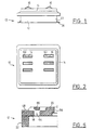
- the connector 10 illustrated in FIGS. 1 to 5 is for the essential consisting of a housing or support made of material insulator 12 and by a cover 14 of molded plastic, and by a series of electrical conductors 16.
- the housing or support 12 essentially consists of a plate horizontal 18 which delimits a flat face 20 and a wall side 22 of substantially rectangular outline.
- the upper face 20 of rectangular outline comprises a series of housings 24 hollowed out in the upper face 20 of plate 18.
- the connector has a general design symmetry by with respect to a median vertical plane P indicated in FIGS. 3 and 4 and the support 12 thus comprises two series of four housings 24 aligned two by two.
- Each housing 24 is in the form of a notch with parallel edges or faces 26 which is delimited by a housing bottom 28 which extends in a plane parallel to the upper flat face 20 of the housing 12.
- Each housing 24 is designed to receive a electrical conductor 16 which is made of a material elastically deformable conductor.
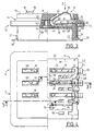
- Each element 16 is thus produced in the form of a contact blade cut and folded.
- Each contact blade 16 extends in a direction general longitudinal contained in a parallel vertical plane to the parallel faces 26 of the corresponding housing 24 and perpendicular to the face 20 of the support 12.
- Each contact blade 16 has a first convex curved end 30 which is intended to cooperate with a corresponding range (not shown) of a card with electronic memory which may be introduced, in a direction I parallel to the housings 24, in a read-write device (not shown) equipped with a connector 10 according to the invention.
- each blade 16 is extended by a spout 32 substantially parallel to the face plane 20 whose function will be explained later.
- Each contact blade 16 also has a connection end 34 which extends vertically, i.e. in a direction perpendicular to the upper face 20, along the side wall 22 of the support 12 and which is ends with a tab folded at a right angle 36 allowing the connection of each blade 16 on a track from a plate to printed circuit (not shown), for example according to the technique of the flat transfer of the components.
- the curved contact end 30 and the end of connection 34 are interconnected by a part median link 38 in the form of a hairpin.
- the middle connecting part 38 of each blade 16 thus comprises a first branch 40 which extends along a direction substantially parallel to the flat face 20 of the support 12 and a second branch 42 forming an acute angle by relative to the first branch 30 and which are interconnected by the U-shaped median fold 44.
- This middle fold 44 is turned towards the center of the connector i.e. it is located substantially at the right of the chip of the smart card when the latter is in read-write position.
- This geometric arrangement gives the connector according to the invention a very high compactness and a low dimensions on the printed circuit board on which it will be mounted.
- the length of the connector, measured parallel to the longitudinal direction of the blades 16 is the as small as possible.
- the free end 46 of the first branch 40 is extended by the connection end 34 of the blade 16 while the free end of the second branch 42 of the middle connecting part 38 extends through the end curved contact 30.
- the free end 46 of the first branch 40 of each blade 16 is kept embedded so that the middle link part 38, and in particular the first branch 40 can flex elastically in a direction D substantially perpendicular to the plane of the plane face of the support 12.
- the end 46 is pinched between a portion plane 48 of the support 12 parallel to the flat face 20 of this last but vertically shifted down from this upper face 20, and a portion of surface corresponding 50 formed opposite in the internal face 52 of the cover 14 which bears against the upper face plane 20 of the support 12.
- the cover 14 is fixed to the housing 12 and by hot crimping thanks to two studs 54 made integrally with the cover 14, which extend vertically downwards from the underside 52 and which are received in two holes correspondents 56 formed in the flat upper wall 18 of the support 12.
- the cover 14 is thus held firmly on support 12 to pinch the ends 46 of the first branches 44 of the middle connecting parts 38 of the blades 16 to ensure their embedding effect in dwellings delimited by surfaces 48 and 50.
- the cover 14 has a series of through slots 60 aligned with the housings 24 and the blades 16.
- the connector 10 is of the type with eight housings 24 but with six contact blades 16 and the cover 14 therefore only has six through slots 60 which are parallel to each other and opposite two by two.
- each contact blade 16 Prior to the introduction of the cover 14, each contact blade 16 is placed in the support 12 by lateral insertion, that is to say substantially according to a direction parallel to the direction of introduction I.
- Each hooking lug 62 extends substantially parallel to branch 40 of the middle connecting part 38 to which it is connected by a crossmember 65.
- Each slot 64 is delimited upwards by a bridge transverse 66 made by molding with support 12 as can be seen in Figure 5.
- Each hooking lug 62 has a heel in projection 68 which extends laterally outwards beyond the connection end 34 of the blade 16 opposite a internal face 70 of a peripheral flange 72 of the cover 14 which thus opposes any accidental lateral escape of the contact blade 16.
- the spout 32 of each blade of contact 30 is held in elastic support against a portion opposite 74 of the underside 52 of the cover 14 in order to determine a precise geometrical position of rest of the curved contact part 30 of each of the blades 16 of so that it occupies a precise geometric position and determined with respect to the support 12.
- the cover 14 thus holds all the blades 16 slightly elastic preload in one position precise geometric.
- the advantage of this design is that it allows vary the contact pressing force on the card studs memory as a function of the exact folding geometry of the middle link part 38, while ensuring a precise dimension protrusion of the curved contact portion 30 by relative to the upper face 76 of the cover 14 of the connector 10.
- the connector 10 which has just been described thus presents very compact while ensuring performance optimal electrical contact of the blades 16 on the pads a card inserted into a read-write device equipped with a connector according to the invention.
- the installation and fixing of the blades 16 in the support 12 is provided mechanically by locking the harpoon-shaped lugs 62 when the mechanical assembly of the blades 16 in the support or case 12 molded beforehand.
- each blade contact 16 which extends from the embedded portion 46 until the curved contact portion 30 is thinned and thus has a reduced thickness "e" compared to the thickness of the metal strip in which the blades of contact are made by cutting and folding.
- This reduced thickness increases the capacity of elastic deformation of each contact blade and allows increase the deflection stroke of each blade contact, and this despite the total height particularly reduced from the connector.
- each contact blade 16 it is possible to provide a hole (not shown) in the recessed portion 46 of the blade, this hole receiving the free end of the spout 32 when the blade is in flexed position.
- the thinning of the intermediate section of each blade is made by local crushing, before cutting blades. This method of obtaining the thinning "e" allows to increase the mechanical characteristics of the material in the area hardened by crushing.
- the design of the body in insulating material 12 with a bottom 18 and parallel faces 26 to delimit the housings 24 which receive the contact blades 12 is particularly advantageous in that it provides a very good electrical insulation of the contacts with respect to the other. This insulation is completed by the design complementary to the slots 60 of the cover 14.
- the connector which just described can be used in a device for read-write in which the electronic memory card is moves relative to the connector in one direction perpendicular to its general plane and perpendicular to the plane of face 20.
- the design of the blades of contact 16 provides a self-cleaning effect due to the cooperation of the curved ends 30 with the tracks conductors of the card during the final landing phase of the latter.
Landscapes
- Engineering & Computer Science (AREA)
- Artificial Intelligence (AREA)
- Computer Vision & Pattern Recognition (AREA)
- Physics & Mathematics (AREA)
- General Physics & Mathematics (AREA)
- Theoretical Computer Science (AREA)
- Coupling Device And Connection With Printed Circuit (AREA)
- Connector Housings Or Holding Contact Members (AREA)
- Details Of Connecting Devices For Male And Female Coupling (AREA)
Claims (11)
- Elektrischer Verbinder (10) zum Anschließen einer elektronischen Speicherkarte mit Mikroschaltkreis, die an einer ihrer Hauptflächen eine Mehrzahl von ausgerichteten elektrischen Kontaktfeldern aufweist, wobei der Verbinder einen Träger (12) aus isolierendem Material, der eine zur Einführungsrichtung (I) der Karte in eine Schreib-/Lesevorrichtung parallele Planfläche (20) und zwei Serien von elektrischen Leitern (16) in Form von elastisch verformbaren Zungen (16) aufweist, die sich parallel zur Einführungsrichtung (I) der Karte erstrecken und paarweise longitudinal ausgerichtet sind, wobei jede Kontaktzunge (16) ein erstes gekrümmtes Kontaktende (30) für den Kontakt mit einem der Felder der Karte, welches über die Ebene der Planfläche (20) des Trägers (12) übersteht, einen mittleren Verbindungsbereich (38) der Zunge (16) zum Träger (12) und ein zweites Ende zum Anschließen (34) der Zunge (16) an eine Verarbeitungsschaltung der Schreib-/Lesevorrichtung umfasst, von dem Typ, bei dem der mittlere Verbindungsbereich (38) jeder Zunge (16) ein in Form einer Haarnadel gebogener Bereich ist, der sich im Wesentlichen parallel zur Planfläche (20) des Trägers (12) erstreckt, der einen ersten Ast (40) umfasst, dessen freies Ende (46) durch das Anschlussende (34) der Zunge (16) verlängert ist, und der Mittel (62) zum Befestigen der Zunge (16) am Träger (12) umfasst, und der einen zweiten Ast (42) umfasst, dessen freies Ende durch das gekrümmte Kontaktende (30) der Zunge (16) verlängert ist, und der erste (40) und der zweite Ast (42) durch eine U-förmige mittlere Biegung (44) verbunden sind, dadurch gekennzeichnet, dass die mittlere Biegung (44) der Mittelebene (P) des Verbinders zugewandt ist, die sich im Wesentlichen über der Mitte der Kontaktfelder der Mikroschaltkreiskarte erstreckt, wenn letztere in Schreib-Leseposition ist.
- Elektrischer Verbinder nach Anspruch 1, dadurch gekennzeichnet, dass das freie Ende (46) des ersten Astes (40) des mittleren Verbindungsbereiches (38) der Zunge (16) in eine Aussparung des Trägers eingespannt ist, und dass der erste Ast (40) sich vor einer gegenüberliegend in der Planfläche (20) des Trägers (12) gebildeten Aussparung (24) erstreckt, um ein Durchbiegen des ersten Astes (40) in einer im Wesentlichen zur Planfläche (20) des Trägers (12) senkrechten Richtung zu ermöglichen.
- Elektrischer Verbinder nach Anspruch 2, dadurch gekennzeichnet, dass das gekrümmte Kontaktende (30) jeder Zunge (16) sich im Wesentlichen über dem eingespannten freien Ende (46) des ersten Astes (40) des mittleren Verbindungsbereichs der Zunge (16) erstreckt.
- Elektrischer Verbinder nach einem der Ansprüche 2 oder 3, dadurch gekennzeichnet, dass die Aussparung (24), vor der sich der erste Ast (40) des mittleren Verbindungsbereiches (38) der Zunge (16) erstreckt, einen zur Planfläche des Trägers (12) parallelen Boden (28) aufweist, der die Durchbiegung des ersten Astes (40) begrenzt.
- Elektrischer Verbinder nach einem beliebigen der vorhergehenden Ansprüche, dadurch gekennzeichnet, dass das gekrümmte Kontaktende (30) jeder Zunge (16) durch einen Schnabel (32) verlängert ist, der in Anlage an einer Anschlagoberfläche (74) elastisch beansprucht ist.
- Elektrischer Verbinder nach einem beliebigen der vorhergehenden Ansprüche, dadurch gekennzeichnet, dass er einen Deckel (14) aus isolierendem Material umfasst, der auf der Planfläche (20) des Trägers (12) aufliegt und der eine Serie von parallelen Schlitzen (60) umfasst, wobei durch jeden der Schlitze ein gekrümmtes Kontaktende (30) einer Zunge (16) übersteht.
- Elektrischer Verbinder nach Anspruch 6 in Kombination mit Anspruch 5, dadurch gekennzeichnet, dass die Anschlagoberfläche (74) gegenüberliegend an der Innenfläche (52) des Deckels (14) gebildet ist, die sich der Planfläche (20) des Trägers (12) zugewandt erstreckt.
- Elektrischer Verbinder nach einem beliebigen der vorhergehenden Ansprüche, dadurch gekennzeichnet, dass das Anschlussende (34) jeder Zunge (16) sich in einer zur Ebene der Planfläche (20) des Trägers (12) senkrechten Richtung vom zweiten Ast (40) des mittleren Verbindungsbereiches (38) der Zunge (16) fort und entlang einer Seitenfläche (22) des Trägers (12) erstreckt.
- Elektrischer Verbinder nach einem beliebigen der vorhergehenden Ansprüche, dadurch gekennzeichnet, dass jede Kontaktzunge (16) in Form eines ausgeschnittenen und gebogenen metallischen Streifens von im Wesentlichen konstanter Dicke ausgebildet ist, und dass jeder Kontaktstreifen einen Zwischenabschnitt von verringerter Dicke (e) umfasst, der insbesondere durch Flachdrücken gebildet ist und der sich zwischen dem Kontaktende und dem Anschlussende der Zunge erstreckt.
- Elektrischer Verbinder nach Anspruch 9, dadurch gekennzeichnet, dass der Abschnitt von verringerter Dicke (e) sich zwischen dem freien Ende (46) des ersten Astes und dem freien Ende des zweiten Astes (42) erstreckt.
- Elektrischer Verbinder nach einem beliebigen der vorhergehenden Ansprüche, dadurch gekennzeichnet, dass das gekrümmte Kontaktende (30) in Längsrichtung zwischen der mittleren Biegung (44), die den ersten (40) und den zweiten Ast (42) des mittleren Verbindungsbereiches verbindet, und dem Anschlussende (34) angeordnet ist.
Priority Applications (1)
| Application Number | Priority Date | Filing Date | Title |
|---|---|---|---|
| DE69433825T DE69433825T3 (de) | 1993-12-24 | 1994-12-26 | Raumsparender elektrischer Verbinder für eine IC-Speicherkarte |
Applications Claiming Priority (3)
| Application Number | Priority Date | Filing Date | Title |
|---|---|---|---|
| FR9315633 | 1993-12-24 | ||
| FR9315633A FR2714539B1 (fr) | 1993-12-24 | 1993-12-24 | Connecteur électrique pour le raccordement d'une carte à mémoire électronique. |
| EP95905168A EP0686289B1 (de) | 1993-12-24 | 1994-12-26 | Elektrischer verbinder zum verbinden von einer elektronischen speicherkarte |
Related Parent Applications (2)
| Application Number | Title | Priority Date | Filing Date |
|---|---|---|---|
| EP95905168A Division EP0686289B1 (de) | 1993-12-24 | 1994-12-26 | Elektrischer verbinder zum verbinden von einer elektronischen speicherkarte |
| EP95905168.1 Division | 1995-07-06 |
Publications (4)
| Publication Number | Publication Date |
|---|---|
| EP0803835A2 EP0803835A2 (de) | 1997-10-29 |
| EP0803835A3 EP0803835A3 (de) | 2000-11-02 |
| EP0803835B1 true EP0803835B1 (de) | 2004-06-02 |
| EP0803835B2 EP0803835B2 (de) | 2012-09-12 |
Family
ID=9454385
Family Applications (3)
| Application Number | Title | Priority Date | Filing Date |
|---|---|---|---|
| EP98201350A Expired - Lifetime EP0860792B1 (de) | 1993-12-24 | 1994-12-26 | Elektrischer Verbinder für elektronische Speicherkarte |
| EP95905168A Expired - Lifetime EP0686289B1 (de) | 1993-12-24 | 1994-12-26 | Elektrischer verbinder zum verbinden von einer elektronischen speicherkarte |
| EP97201929A Expired - Lifetime EP0803835B2 (de) | 1993-12-24 | 1994-12-26 | Raumsparender elektrischer Verbinder für eine IC-Speicherkarte |
Family Applications Before (2)
| Application Number | Title | Priority Date | Filing Date |
|---|---|---|---|
| EP98201350A Expired - Lifetime EP0860792B1 (de) | 1993-12-24 | 1994-12-26 | Elektrischer Verbinder für elektronische Speicherkarte |
| EP95905168A Expired - Lifetime EP0686289B1 (de) | 1993-12-24 | 1994-12-26 | Elektrischer verbinder zum verbinden von einer elektronischen speicherkarte |
Country Status (9)
| Country | Link |
|---|---|
| US (1) | US5980323A (de) |
| EP (3) | EP0860792B1 (de) |
| JP (3) | JP2878457B2 (de) |
| KR (2) | KR100262806B1 (de) |
| CN (3) | CN1049320C (de) |
| DE (3) | DE69433825T3 (de) |
| ES (3) | ES2135692T3 (de) |
| FR (1) | FR2714539B1 (de) |
| WO (1) | WO1995018421A1 (de) |
Families Citing this family (59)
| Publication number | Priority date | Publication date | Assignee | Title |
|---|---|---|---|---|
| FR2720864B1 (fr) | 1994-06-01 | 1996-07-05 | Itt Composants Instr | Connecteur électrique pour le raccordement d'une carte à mémoire électronique comportant un commutateur intégré de détection de la présence d'une carte. |
| FR2720869B1 (fr) * | 1994-06-01 | 1996-07-12 | Itt Composants Instr | Connecteur électrique perfectionné pour le raccordement d'une carte à mémoire électronique. |
| FR2726694B1 (fr) * | 1994-11-07 | 1996-12-06 | Itt Composants Instr | Connecteur electrique pour une carte a memoire electronique comportant des moyens de raccordement electrique du type a deplacement d'isolant |
| FR2733358B1 (fr) * | 1995-04-21 | 1997-05-30 | Itt Composants Instr | Connecteur electrique, notamment pour le raccordement d'une carte a memoire electronique |
| GB9513540D0 (en) * | 1995-07-04 | 1995-09-06 | Elco Europ Ltd | Electrical connectors |
| FR2737352B1 (fr) * | 1995-07-28 | 1997-08-29 | Itt Composants Instr | Connecteur electrique pour le raccordement d'une carte a circuit(s) integre(s) a contact |
| EP0883855B1 (de) * | 1996-02-29 | 1999-12-08 | The Whitaker Corporation | Vorrichtung zur elektrischen verbindung einer chip-karte mit einer leiterplatte |
| DE19608990A1 (de) * | 1996-03-08 | 1997-09-11 | Bosch Gmbh Robert | Chipkarte und Kartenleser für Chipkarten |
| US6315620B1 (en) * | 1997-04-24 | 2001-11-13 | Seagate Technology Llc | System, method, and device for a pre-loaded straddle mounted connector assembly |
| US6326568B2 (en) | 1997-07-02 | 2001-12-04 | Molex Incorporated | Blade switch assembly for a card reader |
| FR2773275B1 (fr) * | 1997-12-26 | 2000-01-28 | Itt Mfg Enterprises Inc | Connecteur electrique de tres faible epaisseur pour le raccordement d'une carte a memoire electronique |
| DE19825808B4 (de) * | 1998-06-09 | 2006-10-26 | Amphenol-Tuchel Electronics Gmbh | Kontaktelement für Chipkartenkontaktiereinrichtung |
| DE19829551C2 (de) * | 1998-07-02 | 2000-12-14 | Amphenol Tuchel Elect | Kontaktträger |
| FI991002A7 (fi) * | 1999-05-03 | 2000-11-04 | Nokia Corp | Toimikorttiliitin ja matkaviestin |
| FR2793353B1 (fr) * | 1999-05-07 | 2001-06-01 | Itt Mfg Enterprises Inc | Connecteur electrique monobloc pour le raccordement d'une carte a circuit(s) integre(s) |
| JP3050871B1 (ja) * | 1999-05-26 | 2000-06-12 | 山一電機株式会社 | 下面接触形コンタクト |
| US6099356A (en) * | 1999-07-19 | 2000-08-08 | Hon Hai Precision Ind. Co., Ltd. | Compression connector |
| TW429652B (en) * | 1999-12-23 | 2001-04-11 | Hon Hai Prec Ind Co Ltd | Electric connector terminal |
| TW515592U (en) * | 2000-01-20 | 2002-12-21 | Hon Hai Prec Ind Co Ltd | Electrical connector |
| US6276941B1 (en) * | 2000-02-22 | 2001-08-21 | Hon Hai Precision Ind. Co., Ltd. | Board to board connector |
| US6758702B2 (en) * | 2000-02-24 | 2004-07-06 | Fci Americas Technology, Inc. | Electrical connector with compression contacts |
| TW438125U (en) * | 2000-03-03 | 2001-05-28 | Hon Hai Prec Ind Co Ltd | Electrical connector |
| US6855013B2 (en) * | 2000-05-08 | 2005-02-15 | Tyco Electronic Logistics Ag | LCD connector for printed circuit boards |
| DE10027600C1 (de) * | 2000-06-02 | 2001-11-22 | Amphenol Tuchel Elect | Kontakt zur Aufnahme in einem Kontaktträger sowie zugehöriger Kontaktträger |
| FR2813446B1 (fr) * | 2000-08-31 | 2006-12-01 | Schlumberger Systems & Service | Appareil electronique comportant un connecteur electrique presentant un contact a deux lames ressorts |
| TW529208B (en) * | 2000-10-13 | 2003-04-21 | J S T Mfg Co Ltd | Electric connector and electric connector with cap |
| JP3912723B2 (ja) * | 2001-04-19 | 2007-05-09 | 日本圧着端子製造株式会社 | Pgaソケット |
| JP4841756B2 (ja) * | 2001-06-08 | 2011-12-21 | 日本圧着端子製造株式会社 | コンタクトとこれを装着した電気コネクタ |
| SG99960A1 (en) * | 2001-11-23 | 2003-11-27 | Fci Asia Technology Pte Ltd | Electrical connector |
| JP4441157B2 (ja) * | 2002-01-28 | 2010-03-31 | パナソニック電工株式会社 | コネクタ |
| US6860766B2 (en) | 2002-03-08 | 2005-03-01 | Cinch Connectors, Inc. | Electrical connector |
| TW540838U (en) * | 2002-05-22 | 2003-07-01 | Benq Corp | Electrical connector and mobile phone using the same |
| TW549629U (en) * | 2002-06-25 | 2003-08-21 | Molex Inc | Electrical connector |
| FR2843654B1 (fr) * | 2002-08-13 | 2006-03-03 | Itt Mfg Entpr S Inc | Agencement pour le raccordement electrique d'un composant sur la face superieure d'une plaque a circuits imprimes |
| DE10238661B3 (de) * | 2002-08-23 | 2004-02-26 | Lumberg Connect Gmbh & Co. Kg | Elektrische Kontaktiervorrichtung, insbesondere zur Verbindung einer Spannungsquelle mit einer elektronischen Schaltung |
| SG118181A1 (en) * | 2003-03-25 | 2006-01-27 | Fci Asia Technology Pte Ltd | High density electrical connector |
| US7625216B2 (en) * | 2003-06-11 | 2009-12-01 | Cinch Connectors, Inc. | Electrical connector |
| US7455556B2 (en) * | 2003-06-11 | 2008-11-25 | Cinch Connectors, Inc. | Electrical contact |
| US6921270B2 (en) | 2003-06-11 | 2005-07-26 | Cinch Connectors, Inc. | Electrical connector |
| US7674143B2 (en) * | 2003-09-17 | 2010-03-09 | Ngk Spark Plug Co., Ltd. | Sensor and method of producing sensor |
| JP4307344B2 (ja) * | 2004-07-20 | 2009-08-05 | シチズン電子株式会社 | 表面実装型モジュール |
| US6955572B1 (en) * | 2004-07-22 | 2005-10-18 | Hon Hai Precision Ind. Co., Ltd | LGA contact with extended arm for IC connector |
| TWM280586U (en) * | 2005-04-01 | 2005-11-11 | Hon Hai Prec Ind Co Ltd | Electrical card connector |
| DE502005002999D1 (de) | 2005-06-23 | 2008-04-10 | Hopt & Schuler Ddm | Kartenleser mit symmetrischer Kontaktfeder |
| DE502005004005D1 (de) * | 2005-06-23 | 2008-06-19 | Hopt & Schuler Ddm | Kartenleser mit doppel-U-förmig angeordneten Kontaktfedern |
| FI120069B (fi) * | 2006-10-20 | 2009-06-15 | Perlos Oyj | Board-to-board liitin ja sovitelma kahden piirilevyn yhteydessä |
| CN101212095B (zh) * | 2006-12-26 | 2012-01-11 | 富士康(昆山)电脑接插件有限公司 | 电连接器端子 |
| GB2445380B (en) * | 2007-01-04 | 2009-12-02 | Motorola Inc | Electrical connector and connector module |
| JP5238928B2 (ja) * | 2007-04-19 | 2013-07-17 | 並木精密宝石株式会社 | 給電端子構造 |
| KR101005767B1 (ko) | 2008-06-24 | 2011-01-06 | 주식회사 이엠따블유 | 전기적 접속을 위한 핀 |
| JP2010073341A (ja) * | 2008-09-16 | 2010-04-02 | Kitagawa Ind Co Ltd | 表面実装コンタクト |
| JP5778696B2 (ja) | 2010-02-12 | 2015-09-16 | エーディーシー テレコミュニケーションズ,インコーポレイティド | 管理されたファイバ接続システム |
| SG176335A1 (en) | 2010-05-27 | 2011-12-29 | Molex Singapore Pte Ltd | Electronic card connector |
| US8079851B1 (en) * | 2010-11-11 | 2011-12-20 | Hon Hai Precision Ind. Co., Ltd. | Socket with lower contact |
| FR2968466B1 (fr) | 2010-12-07 | 2013-10-25 | Injection Haute Prec | Contact et connecteur de carte a microcircuit |
| JP6025194B2 (ja) * | 2012-11-12 | 2016-11-16 | 北川工業株式会社 | コンタクト |
| JP6941000B2 (ja) * | 2017-08-09 | 2021-09-29 | ヒロセ電機株式会社 | 回路基板用電気コネクタおよびその製造方法 |
| TWM602744U (zh) * | 2020-01-20 | 2020-10-11 | 唐虞企業股份有限公司 | 受力機構及其構成的連接器 |
| CN115732967A (zh) * | 2022-11-29 | 2023-03-03 | 昆山宏泽电子有限公司 | 免焊接电连接器 |
Family Cites Families (23)
| Publication number | Priority date | Publication date | Assignee | Title |
|---|---|---|---|---|
| NL286406A (de) † | 1961-12-12 | |||
| US3771109A (en) † | 1972-05-01 | 1973-11-06 | Bunker Ramo | Electrical connector for integrated circuit device |
| US4553192A (en) † | 1983-08-25 | 1985-11-12 | International Business Machines Corporation | High density planar interconnected integrated circuit package |
| JPS6111284U (ja) * | 1984-06-26 | 1986-01-23 | 沖電線株式会社 | 基板接続コネクタ |
| FR2587549B1 (fr) * | 1985-09-13 | 1988-03-04 | Radiotechnique | Systeme d'interconnexion |
| DE8529580U1 (de) † | 1985-10-18 | 1986-01-09 | Preh, Elektrofeinmechanische Werke Jakob Preh Nachf. Gmbh & Co, 8740 Bad Neustadt | Gerät zum Auswerten einer Informationsträgerkarte |
| DE3602668A1 (de) * | 1986-01-29 | 1987-07-30 | Allied Corp | Kontaktiereinrichtung fuer eine chip-karte |
| JPH0326628Y2 (de) * | 1986-06-24 | 1991-06-10 | ||
| GB2214680B (en) * | 1988-01-19 | 1991-07-31 | Technophone Ltd | Card reader |
| KR910001533A (ko) * | 1988-06-30 | 1991-01-31 | 아오이 죠이치 | Ic카드독출/기록장치 |
| FR2638293B1 (fr) * | 1988-10-26 | 1991-01-18 | Itt Composants Instr | Connecteur electrique pour cartes a memoire electronique, procede de realisation d'un tel connecteur et dispositif de lecture-ecriture integrant un tel connecteur |
| DE8908801U1 (de) * | 1989-07-19 | 1989-09-07 | Siemens AG, 1000 Berlin und 8000 München | Kartenleser mit einem in einer Aufnahme entgegen Federkraft verschiebbaren Schlitten |
| DE59108764D1 (de) * | 1990-01-30 | 1997-08-14 | Amphenol Tuchel Elect | Kontaktiereinrichtung für ein SI-Modul |
| NL9001061A (nl) * | 1990-05-03 | 1991-12-02 | Philips Nv | Inrichting bevattende een kunststofhuis met kanalen voor het bevestigen van contactorganen. |
| ES2061121T3 (es) * | 1991-06-28 | 1994-12-01 | Molex Inc | Conectador de tarjeta de c i (circuitos integrados). |
| JPH05114444A (ja) * | 1991-10-14 | 1993-05-07 | Minnesota Mining & Mfg Co <3M> | 圧入型接触子を有するコネクタ |
| JP2598581Y2 (ja) * | 1991-12-03 | 1999-08-16 | 矢崎総業株式会社 | コネクタ |
| US5154644A (en) * | 1992-01-15 | 1992-10-13 | Molex Incorporated | Edge connector for a printed circuit card |
| JP2761489B2 (ja) * | 1992-04-06 | 1998-06-04 | モレックス インコーポレーテッド | 電気コネクタ |
| IE80506B1 (en) * | 1992-05-08 | 1998-08-26 | Molex Inc | Electrical connector with contact anti-overstress means |
| US5425651A (en) * | 1994-03-04 | 1995-06-20 | The Whitaker Corporation | Card edge connector providing non-simultaneous electrical connections |
| FR2726694B1 (fr) * | 1994-11-07 | 1996-12-06 | Itt Composants Instr | Connecteur electrique pour une carte a memoire electronique comportant des moyens de raccordement electrique du type a deplacement d'isolant |
| FR2737352B1 (fr) * | 1995-07-28 | 1997-08-29 | Itt Composants Instr | Connecteur electrique pour le raccordement d'une carte a circuit(s) integre(s) a contact |
-
1993
- 1993-12-24 FR FR9315633A patent/FR2714539B1/fr not_active Expired - Fee Related
-
1994
- 1994-12-26 ES ES95905168T patent/ES2135692T3/es not_active Expired - Lifetime
- 1994-12-26 KR KR1019970704124A patent/KR100262806B1/ko not_active Expired - Fee Related
- 1994-12-26 EP EP98201350A patent/EP0860792B1/de not_active Expired - Lifetime
- 1994-12-26 ES ES98201350T patent/ES2227764T3/es not_active Expired - Lifetime
- 1994-12-26 ES ES97201929T patent/ES2217365T3/es not_active Expired - Lifetime
- 1994-12-26 DE DE69433825T patent/DE69433825T3/de not_active Expired - Lifetime
- 1994-12-26 WO PCT/FR1994/001532 patent/WO1995018421A1/fr not_active Ceased
- 1994-12-26 CN CN94191281A patent/CN1049320C/zh not_active Expired - Fee Related
- 1994-12-26 JP JP7517814A patent/JP2878457B2/ja not_active Expired - Lifetime
- 1994-12-26 EP EP95905168A patent/EP0686289B1/de not_active Expired - Lifetime
- 1994-12-26 DE DE69419406T patent/DE69419406T2/de not_active Expired - Lifetime
- 1994-12-26 EP EP97201929A patent/EP0803835B2/de not_active Expired - Lifetime
- 1994-12-26 CN CNB971146462A patent/CN1160652C/zh not_active Expired - Fee Related
- 1994-12-26 DE DE69434153T patent/DE69434153T2/de not_active Expired - Lifetime
- 1994-12-26 KR KR1019950703583A patent/KR100242733B1/ko not_active Expired - Lifetime
-
1997
- 1997-07-07 US US08/888,435 patent/US5980323A/en not_active Expired - Lifetime
- 1997-07-11 JP JP18640897A patent/JP3195567B2/ja not_active Expired - Lifetime
-
1998
- 1998-04-16 CN CN98106940A patent/CN1124561C/zh not_active Expired - Fee Related
- 1998-06-24 JP JP17756698A patent/JP3443001B2/ja not_active Expired - Lifetime
Also Published As
Similar Documents
| Publication | Publication Date | Title |
|---|---|---|
| EP0803835B1 (de) | Raumsparender elektrischer Verbinder für eine IC-Speicherkarte | |
| EP0738429B1 (de) | Elektrischer verbinder für eine elektronische speicherkarte mit elektrischen isolationverdrängungsverbindern | |
| EP0316700B1 (de) | Kontaktrahmen für I.S.-Kartenleser | |
| EP0756355A1 (de) | Elektrischer Steckverbinder zur Verbindung mit den Kontakten einer integrierten gedruckten Schaltung | |
| EP0766875B1 (de) | Elektrischer verbinder insbesondere für den anschluss einer elektronischen speicherkarte | |
| FR2821988A1 (fr) | Connecteur electrique pour cartes a memoire electronique a grande capacite de stockage | |
| FR2773275A1 (fr) | Connecteur electrique de tres faible epaisseur pour le raccordement d'une carte a memoire electronique | |
| FR2495846A1 (fr) | Dispositif de connexion electrique a haute densite de contacts | |
| EP0942492A2 (de) | Gehäuse zur elektronischen Verbindung an einen Computer ausgerüstet mit einem IC-Karten-Verbinder | |
| FR2803110A1 (fr) | Connecteur pour carte a microcircuit et procede de montage d'une telle carte dans ce connecteur | |
| FR2771846A1 (fr) | Commutateur electrique a effet tactile a plusieurs voies et a organe de declenchement unique | |
| EP0660253B1 (de) | Kontaktstreifen und diesen enthaltender Verbinder | |
| EP0711438B1 (de) | Elektrischer verbinder zum verbinden einer elektronischen speicherkarte, mit einem integrierten schalter, der die anwesenheit einer karte erkennt | |
| FR2773244A1 (fr) | Commutateur de detection de la presence d'une carte a memoire electronique dans un dispositif de lecture-ecriture | |
| EP1588459A1 (de) | Mit druckkontaktanschlüssen ausgestattetersteckverbinder | |
| WO1997041578A1 (fr) | Carte a circuit integre de faible epaisseur comportant un commutateur perfectionne a actionnement manuel | |
| FR2771834A1 (fr) | Dispositif de connexion electrique pour cooperer avec un support electronique mobile | |
| FR2773246A1 (fr) | Commutateur electrique miniaturise, integre a un connecteur, pour la detection de la presence d'une carte a memoire electronique | |
| EP0656597B1 (de) | Kartenkontaktrahmen und -verbinder | |
| EP0711440B1 (de) | Elektrische kontakteinheit zum kontaktieren einer elektronischen speicherkarte | |
| FR2720865A1 (fr) | Commutateur de détection de la présence d'une carte à mémoire électronique dans un dispositif de lecture-écriture. | |
| WO1998041946A1 (fr) | Connecteur pour lecteur de carte, a contacts balais elastiques, et lecteur comportant un tel connecteur | |
| FR2843654A1 (fr) | Agencement pour le raccordement electrique d'un composant sur la face superieure d'une plaque a circuits imprimes | |
| FR2658364A1 (fr) | Connecteur electrique pour cartes a memoire electronique. | |
| FR2733370A1 (fr) | Connecteur electrique pour le raccordement du bloc d'alimentation d'un appareil faisant appel a une carte a memoire electronique pour son fonctionnement |
Legal Events
| Date | Code | Title | Description |
|---|---|---|---|
| PUAI | Public reference made under article 153(3) epc to a published international application that has entered the european phase |
Free format text: ORIGINAL CODE: 0009012 |
|
| AC | Divisional application: reference to earlier application |
Ref document number: 686289 Country of ref document: EP |
|
| AK | Designated contracting states |
Kind code of ref document: A2 Designated state(s): DE ES FR GB IT SE |
|
| PUAL | Search report despatched |
Free format text: ORIGINAL CODE: 0009013 |
|
| AK | Designated contracting states |
Kind code of ref document: A3 Designated state(s): DE ES FR GB IT SE |
|
| RIC1 | Information provided on ipc code assigned before grant |
Free format text: 7G 06K 7/06 A, 7G 06K 7/00 B |
|
| 17P | Request for examination filed |
Effective date: 20010208 |
|
| 17Q | First examination report despatched |
Effective date: 20021011 |
|
| RAP1 | Party data changed (applicant data changed or rights of an application transferred) |
Owner name: ITT MANUFACTURING ENTERPRISES, INC. |
|
| GRAP | Despatch of communication of intention to grant a patent |
Free format text: ORIGINAL CODE: EPIDOSNIGR1 |
|
| GRAS | Grant fee paid |
Free format text: ORIGINAL CODE: EPIDOSNIGR3 |
|
| GRAA | (expected) grant |
Free format text: ORIGINAL CODE: 0009210 |
|
| AC | Divisional application: reference to earlier application |
Ref document number: 0686289 Country of ref document: EP Kind code of ref document: P |
|
| AK | Designated contracting states |
Kind code of ref document: B1 Designated state(s): DE ES FR GB IT SE |
|
| PG25 | Lapsed in a contracting state [announced via postgrant information from national office to epo] |
Ref country code: IT Free format text: LAPSE BECAUSE OF FAILURE TO SUBMIT A TRANSLATION OF THE DESCRIPTION OR TO PAY THE FEE WITHIN THE PRESCRIBED TIME-LIMIT;WARNING: LAPSES OF ITALIAN PATENTS WITH EFFECTIVE DATE BEFORE 2007 MAY HAVE OCCURRED AT ANY TIME BEFORE 2007. THE CORRECT EFFECTIVE DATE MAY BE DIFFERENT FROM THE ONE RECORDED. Effective date: 20040602 |
|
| REG | Reference to a national code |
Ref country code: GB Ref legal event code: FG4D Free format text: NOT ENGLISH |
|
| REF | Corresponds to: |
Ref document number: 69433825 Country of ref document: DE Date of ref document: 20040708 Kind code of ref document: P |
|
| REG | Reference to a national code |
Ref country code: SE Ref legal event code: TRGR |
|
| GBT | Gb: translation of ep patent filed (gb section 77(6)(a)/1977) |
Effective date: 20040826 |
|
| REG | Reference to a national code |
Ref country code: ES Ref legal event code: FG2A Ref document number: 2217365 Country of ref document: ES Kind code of ref document: T3 |
|
| PGFP | Annual fee paid to national office [announced via postgrant information from national office to epo] |
Ref country code: SE Payment date: 20041221 Year of fee payment: 11 |
|
| PGFP | Annual fee paid to national office [announced via postgrant information from national office to epo] |
Ref country code: ES Payment date: 20050110 Year of fee payment: 11 |
|
| PLAQ | Examination of admissibility of opposition: information related to despatch of communication + time limit deleted |
Free format text: ORIGINAL CODE: EPIDOSDOPE2 |
|
| PLBQ | Unpublished change to opponent data |
Free format text: ORIGINAL CODE: EPIDOS OPPO |
|
| PLAQ | Examination of admissibility of opposition: information related to despatch of communication + time limit deleted |
Free format text: ORIGINAL CODE: EPIDOSDOPE2 |
|
| PLBQ | Unpublished change to opponent data |
Free format text: ORIGINAL CODE: EPIDOS OPPO |
|
| PLBI | Opposition filed |
Free format text: ORIGINAL CODE: 0009260 |
|
| PLAQ | Examination of admissibility of opposition: information related to despatch of communication + time limit deleted |
Free format text: ORIGINAL CODE: EPIDOSDOPE2 |
|
| PLAR | Examination of admissibility of opposition: information related to receipt of reply deleted |
Free format text: ORIGINAL CODE: EPIDOSDOPE4 |
|
| PLBQ | Unpublished change to opponent data |
Free format text: ORIGINAL CODE: EPIDOS OPPO |
|
| PLAB | Opposition data, opponent's data or that of the opponent's representative modified |
Free format text: ORIGINAL CODE: 0009299OPPO |
|
| PLAX | Notice of opposition and request to file observation + time limit sent |
Free format text: ORIGINAL CODE: EPIDOSNOBS2 |
|
| 26 | Opposition filed |
Opponent name: THE WHITAKER CORPORATION Effective date: 20050301 Opponent name: DDM HOPT & SCHULER GMBH & CO. KG Effective date: 20050225 |
|
| R26 | Opposition filed (corrected) |
Opponent name: THE WHITAKER CORPORATION Effective date: 20050301 Opponent name: DDM HOPT & SCHULER GMBH & CO. KG Effective date: 20050225 |
|
| PLAF | Information modified related to communication of a notice of opposition and request to file observations + time limit |
Free format text: ORIGINAL CODE: EPIDOSCOBS2 |
|
| PLBB | Reply of patent proprietor to notice(s) of opposition received |
Free format text: ORIGINAL CODE: EPIDOSNOBS3 |
|
| PG25 | Lapsed in a contracting state [announced via postgrant information from national office to epo] |
Ref country code: SE Free format text: LAPSE BECAUSE OF NON-PAYMENT OF DUE FEES Effective date: 20051227 Ref country code: ES Free format text: LAPSE BECAUSE OF NON-PAYMENT OF DUE FEES Effective date: 20051227 |
|
| EUG | Se: european patent has lapsed | ||
| REG | Reference to a national code |
Ref country code: ES Ref legal event code: FD2A Effective date: 20051227 |
|
| RAP2 | Party data changed (patent owner data changed or rights of a patent transferred) |
Owner name: COACTIVE TECHNOLOGIES, INC. |
|
| REG | Reference to a national code |
Ref country code: GB Ref legal event code: 732E |
|
| APBP | Date of receipt of notice of appeal recorded |
Free format text: ORIGINAL CODE: EPIDOSNNOA2O |
|
| APAH | Appeal reference modified |
Free format text: ORIGINAL CODE: EPIDOSCREFNO |
|
| APBP | Date of receipt of notice of appeal recorded |
Free format text: ORIGINAL CODE: EPIDOSNNOA2O |
|
| REG | Reference to a national code |
Ref country code: FR Ref legal event code: TP |
|
| PLAB | Opposition data, opponent's data or that of the opponent's representative modified |
Free format text: ORIGINAL CODE: 0009299OPPO |
|
| R26 | Opposition filed (corrected) |
Opponent name: THE WHITAKER CORPORATION Effective date: 20050301 Opponent name: DDM HOPT & SCHULER GMBH & CO. KG Effective date: 20050225 |
|
| APBQ | Date of receipt of statement of grounds of appeal recorded |
Free format text: ORIGINAL CODE: EPIDOSNNOA3O |
|
| PLAB | Opposition data, opponent's data or that of the opponent's representative modified |
Free format text: ORIGINAL CODE: 0009299OPPO |
|
| APBU | Appeal procedure closed |
Free format text: ORIGINAL CODE: EPIDOSNNOA9O |
|
| RAP2 | Party data changed (patent owner data changed or rights of a patent transferred) |
Owner name: COACTIVE TECHNOLOGIES, LLC |
|
| REG | Reference to a national code |
Ref country code: DE Ref legal event code: R082 Ref document number: 69433825 Country of ref document: DE Representative=s name: DREISS PATENTANWAELTE, DE |
|
| REG | Reference to a national code |
Ref country code: DE Ref legal event code: R082 Ref document number: 69433825 Country of ref document: DE Representative=s name: DREISS PATENTANWAELTE PARTG MBB, DE Effective date: 20120201 Ref country code: DE Ref legal event code: R082 Ref document number: 69433825 Country of ref document: DE Representative=s name: DREISS PATENTANWAELTE PARTNERSCHAFT, DE Effective date: 20120201 Ref country code: DE Ref legal event code: R081 Ref document number: 69433825 Country of ref document: DE Owner name: COACTIVE TECHNOLOGIES, LLC, NEWTON, US Free format text: FORMER OWNER: COACTIVE TECHNOLOGIES, INC., GREENWICH, CONN., US Effective date: 20120201 Ref country code: DE Ref legal event code: R081 Ref document number: 69433825 Country of ref document: DE Owner name: DELTATECH CONTROLS USA, LLC, US Free format text: FORMER OWNER: COACTIVE TECHNOLOGIES, INC., GREENWICH, US Effective date: 20120201 Ref country code: DE Ref legal event code: R081 Ref document number: 69433825 Country of ref document: DE Owner name: COACTIVE TECHNOLOGIES, LLC, US Free format text: FORMER OWNER: COACTIVE TECHNOLOGIES, INC., GREENWICH, US Effective date: 20120201 |
|
| PUAH | Patent maintained in amended form |
Free format text: ORIGINAL CODE: 0009272 |
|
| STAA | Information on the status of an ep patent application or granted ep patent |
Free format text: STATUS: PATENT MAINTAINED AS AMENDED |
|
| 27A | Patent maintained in amended form |
Effective date: 20120912 |
|
| AK | Designated contracting states |
Kind code of ref document: B2 Designated state(s): DE ES FR GB IT SE |
|
| REG | Reference to a national code |
Ref country code: DE Ref legal event code: R082 Ref document number: 69433825 Country of ref document: DE Representative=s name: DREISS PATENTANWAELTE PARTNERSCHAFT, DE |
|
| REG | Reference to a national code |
Ref country code: DE Ref legal event code: R102 Ref document number: 69433825 Country of ref document: DE Effective date: 20120912 |
|
| REG | Reference to a national code |
Ref country code: DE Ref legal event code: R082 Ref document number: 69433825 Country of ref document: DE Representative=s name: DREISS PATENTANWAELTE PARTNERSCHAFT, DE |
|
| REG | Reference to a national code |
Ref country code: DE Ref legal event code: R082 Ref document number: 69433825 Country of ref document: DE Representative=s name: DREISS PATENTANWAELTE PARTG MBB, DE Effective date: 20121121 Ref country code: DE Ref legal event code: R082 Ref document number: 69433825 Country of ref document: DE Representative=s name: DREISS PATENTANWAELTE PARTG MBB, DE Effective date: 20120919 Ref country code: DE Ref legal event code: R082 Ref document number: 69433825 Country of ref document: DE Representative=s name: DREISS PATENTANWAELTE PARTNERSCHAFT, DE Effective date: 20120919 Ref country code: DE Ref legal event code: R082 Ref document number: 69433825 Country of ref document: DE Representative=s name: DREISS PATENTANWAELTE PARTNERSCHAFT, DE Effective date: 20121121 Ref country code: DE Ref legal event code: R081 Ref document number: 69433825 Country of ref document: DE Owner name: COACTIVE TECHNOLOGIES, LLC, NEWTON, US Free format text: FORMER OWNER: COACTIVE TECHNOLOGIES, LLC, NEWTON, MASS., US Effective date: 20121121 Ref country code: DE Ref legal event code: R081 Ref document number: 69433825 Country of ref document: DE Owner name: DELTATECH CONTROLS USA, LLC, US Free format text: FORMER OWNER: COACTIVE TECHNOLOGIES, LLC, NEWTON, US Effective date: 20121121 Ref country code: DE Ref legal event code: R081 Ref document number: 69433825 Country of ref document: DE Owner name: COACTIVE TECHNOLOGIES, LLC, US Free format text: FORMER OWNER: COACTIVE TECHNOLOGIES, LLC, NEWTON, US Effective date: 20121121 |
|
| REG | Reference to a national code |
Ref country code: DE Ref legal event code: R082 Ref document number: 69433825 Country of ref document: DE Representative=s name: DREISS PATENTANWAELTE PARTNERSCHAFT, DE |
|
| REG | Reference to a national code |
Ref country code: DE Ref legal event code: R082 Ref document number: 69433825 Country of ref document: DE Representative=s name: DREISS PATENTANWAELTE PARTG MBB, DE Effective date: 20130129 Ref country code: DE Ref legal event code: R082 Ref document number: 69433825 Country of ref document: DE Representative=s name: DREISS PATENTANWAELTE PARTNERSCHAFT, DE Effective date: 20130129 Ref country code: DE Ref legal event code: R081 Ref document number: 69433825 Country of ref document: DE Owner name: COACTIVE TECHNOLOGIES, LLC, NEWTON, US Free format text: FORMER OWNER: DELTATECH CONTROLS USA, LLC, NEWTON, MASS., US Effective date: 20130129 Ref country code: DE Ref legal event code: R081 Ref document number: 69433825 Country of ref document: DE Owner name: COACTIVE TECHNOLOGIES, LLC, US Free format text: FORMER OWNER: DELTATECH CONTROLS USA, LLC, NEWTON, US Effective date: 20130129 |
|
| PGFP | Annual fee paid to national office [announced via postgrant information from national office to epo] |
Ref country code: GB Payment date: 20131227 Year of fee payment: 20 Ref country code: DE Payment date: 20131230 Year of fee payment: 20 |
|
| PGFP | Annual fee paid to national office [announced via postgrant information from national office to epo] |
Ref country code: FR Payment date: 20131217 Year of fee payment: 20 |
|
| REG | Reference to a national code |
Ref country code: DE Ref legal event code: R071 Ref document number: 69433825 Country of ref document: DE |
|
| REG | Reference to a national code |
Ref country code: DE Ref legal event code: R071 Ref document number: 69433825 Country of ref document: DE |
|
| REG | Reference to a national code |
Ref country code: GB Ref legal event code: PE20 Expiry date: 20141225 |
|
| PG25 | Lapsed in a contracting state [announced via postgrant information from national office to epo] |
Ref country code: GB Free format text: LAPSE BECAUSE OF EXPIRATION OF PROTECTION Effective date: 20141225 |