EP0803745A1 - Faseroptisches Element - Google Patents
Faseroptisches Element Download PDFInfo
- Publication number
- EP0803745A1 EP0803745A1 EP97302740A EP97302740A EP0803745A1 EP 0803745 A1 EP0803745 A1 EP 0803745A1 EP 97302740 A EP97302740 A EP 97302740A EP 97302740 A EP97302740 A EP 97302740A EP 0803745 A1 EP0803745 A1 EP 0803745A1
- Authority
- EP
- European Patent Office
- Prior art keywords
- optical
- optical member
- angle
- face
- incident
- Prior art date
- Legal status (The legal status is an assumption and is not a legal conclusion. Google has not performed a legal analysis and makes no representation as to the accuracy of the status listed.)
- Granted
Links
Images


Classifications
-
- G—PHYSICS
- G02—OPTICS
- G02B—OPTICAL ELEMENTS, SYSTEMS OR APPARATUS
- G02B6/00—Light guides; Structural details of arrangements comprising light guides and other optical elements, e.g. couplings
- G02B6/24—Coupling light guides
- G02B6/42—Coupling light guides with opto-electronic elements
- G02B6/4201—Packages, e.g. shape, construction, internal or external details
- G02B6/4249—Packages, e.g. shape, construction, internal or external details comprising arrays of active devices and fibres
-
- G—PHYSICS
- G02—OPTICS
- G02B—OPTICAL ELEMENTS, SYSTEMS OR APPARATUS
- G02B6/00—Light guides; Structural details of arrangements comprising light guides and other optical elements, e.g. couplings
- G02B6/04—Light guides; Structural details of arrangements comprising light guides and other optical elements, e.g. couplings formed by bundles of fibres
- G02B6/06—Light guides; Structural details of arrangements comprising light guides and other optical elements, e.g. couplings formed by bundles of fibres the relative position of the fibres being the same at both ends, e.g. for transporting images
- G02B6/08—Light guides; Structural details of arrangements comprising light guides and other optical elements, e.g. couplings formed by bundles of fibres the relative position of the fibres being the same at both ends, e.g. for transporting images with fibre bundle in form of plate
-
- G—PHYSICS
- G02—OPTICS
- G02B—OPTICAL ELEMENTS, SYSTEMS OR APPARATUS
- G02B6/00—Light guides; Structural details of arrangements comprising light guides and other optical elements, e.g. couplings
- G02B6/24—Coupling light guides
- G02B6/26—Optical coupling means
- G02B6/262—Optical details of coupling light into, or out of, or between fibre ends, e.g. special fibre end shapes or associated optical elements
Definitions
- the present invention relates to a fiber optics device used for fingerprint detection and the like.
- a fiber optics device is used as a means for converting the three-dimensional surface shape of a detection target into an optical image.
- a fiber optics device As an example which practically uses such a fiber optics device as a fingerprint detecting apparatus, one described in Japanese Patent Laid-Open No. 7-174947 is known.
- the direction of an optical axis of optical fibers constituting the fiber optics device is inclined by an inclination angle ⁇ with respect to the incident angle and exit angle, as shown in Fig. 11 of the reference.
- a CCD is mounted on this exit surface.
- the incident surface and the exit surface are formed to be inclined with respect to the direction of the optical axis, in order to prevent light from becoming incident on the fiber optics device directly from the external air. Also, the distance between a surface with which a finger as a detection target comes in contact (the incident surface of the fiber optics device) and the CCD is decreased, in order to decrease the size of the fingerprint detecting apparatus.
- the light exit surface is also inclined with respect to the direction of the optical axis of the optical fibers, even if a fingerprint image is incident on the fiber optics device through the finger which has come in contact with the light-incident angle, light does not efficiently emerge to the external air from the image exit surface. Even if a CCD is mounted on the exit surface to change the exit characteristics, the quantity of light emerging from the exit surface is very small, and the image of a fingerprint to be detected tends to be dark accordingly.
- a fiber optics device comprising: a first optical member obtained by integrating a plurality of optical fibers of a first type by bundling and having first and second end faces, the first end face obliquely intersecting an image transmitting direction at a first angle, the second end face being substantially parallel to the first end face thereof, and the optical fibers of the first type having a first numerical aperture and cores with a first refractive index; and a second optical member obtained by integrating a plurality of optical fibers of a second type by bundling and having first and second end faces, the first end face obliquely intersecting the image transmitting direction at a second angle, the second end face being substantially parallel to the first end face thereof, the optical fibers of the second type having a second numerical aperture larger than the first numerical aperture and cores with a second refractive index, and the first end face of the second optical member being bonded to the second end face of the first optical member.
- the first optical member propagates through the first optical member and emerges toward the second optical member. Since the optical fibers of the second type have a numerical aperture larger than that of the optical fibers of the first type, the range of exit angle of light emerging from the exit surface of the second optical member is wide.
- the first angle can be set smaller than the second angle.
- the first refractive index is preferably equal to or less than the second refractive index.
- light which has become incident on the second optical member propagates substantially entirely along the second optical member.
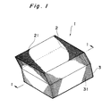
- Figs. 1 and 2 are overall schematic views of a fiber optics device 1.
- the fiber optics device 1 is constituted by a first optical member 2 and a second optical member 3, and the first and second optical members 2 and 3 are stacked and bonded to each other.
- the first optical member 2 is obtained by integrating, by bundling, a plurality of optical fibers 21 directed in the same direction, and has surfaces 22 and 23 formed obliquely to the direction of an optical axis of the optical fibers 21.
- the surfaces 22 and 23 of the first optical member 2 oppose each other to be parallel to each other, and are formed at a predetermined inclination angle ⁇ 2 and not to be perpendicular or parallel to the direction of the optical axis of the optical fibers 21.
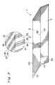
- a cladding layer 25 is formed on a core 24, and the refractive index of the core 24 is set to be larger than that of the cladding layer 25.
- absorbers 26 are disposed among the optical fibers 21. Hence, when light incident on an arbitrary optical fiber 21 propagates outside the cladding layer 25, it disappears as it is absorbed by the absorbers 26, so that it will not leak to the adjacent optical fibers 21.
- the inclination angle ⁇ 2 of the first optical member 2 described above is set to such a value that light incident on the optical fibers 21 of the first optical member 2 from the air will not propagate in the optical fibers 21.
- ⁇ is the angle of refraction of light in the optical fibers 21 when the light becomes incident on the optical fibers 21 from a direction substantially parallel to the surface 22
- ⁇ is the critical incident angle when this light becomes incident on the boundary surface between the core 24 and the cladding layer 25 as it propagates while repeating total reflection on the boundary surface
- n 0 is the refractive index of air
- n 24 is the
- inclination angle ⁇ 2 37° is calculated from these equations (1), (2), and (3). Therefore, when the inclination angle ⁇ 2 is set to a value smaller than 37°, even if light becomes incident from the air to the optical fibers 21 of the first optical member 2, this light does not propagate in the optical fibers 21. In other words, if the inclination angle ⁇ 2 ( ⁇ 37°) is set, light incident from the air to the first optical member 2 will not emerge from the first optical member 2, but only light incident on the first optical member 2 through an object which is in contact with the surface 22 emerges.
- the second optical member 3 is obtained by integrating, by bundling, a plurality of optical fibers 31 in the same direction, in the same manner as the first optical member 2.
- the second optical member 3 has surfaces 32 and 33 that are formed obliquely to the direction of an optical axis of the optical fibers 31. More specifically, the surfaces 32 and 33 of the second optical member 3 are formed to oppose each other to be parallel to each other, and are formed at a predetermined inclination angle ⁇ 2 and not perpendicular or parallel to the direction of the optical axis of the optical fibers 31.
- each optical fiber 31 constituting the second optical member 3 a cladding layer 35 is formed on a core 34, and the refractive index of the core 34 is set to be larger than that of the cladding layer 35. As a result, light can propagate along the core 34. Furthermore, absorbers 36 are disposed among the optical fibers 31. Hence, light becoming incident on an arbitrary optical fiber 31 does not leak to the adjacent optical fibers 31.
- the surface 32 of the second optical member 3 is bonded to the surface 23 of the first optical member 2, so that light emerging from the first optical member 2 can become incident on the surface 32.
- the second optical member 3 has a larger numerical aperture than that of the first optical member 2.
- the optical fibers 31 of the second optical member 3 have a numerical aperture larger than that of the optical fibers 21 of the first optical member 2.
- the numerical aperture NA As the numerical aperture NA increases, the optical propagation loss in the optical fibers 31 tends to increase. Hence, the numerical aperture NA is set to an appropriate large value, e.g., about 1.0.
- the refractive index n34 of the cores 34 of the second optical member 3 is set to be larger than the refractive index n 24 of the cores 24 of the first optical member 2.
- the refractive index n 24 of the cores 24 of the first optical member 2 is 1.56, the refractive index n 34 of the cores 34 of the second optical member 3 is 1.82. Therefore, light propagating from the first optical member 2 to the second optical member 3 becomes incident on the second optical member 3 without being totally reflected by the bonding portion (boundary portion) between the first and second optical members 2 and 3, thereby preventing a loss in optical propagation.
- the inclination angle ⁇ 3 of the second optical member 3 described above is preferably set such that light that has propagated through the first optical member 2 and becomes incident on the second optical member 3 from the first optical member 2 at the maximum incident angle is incident on the boundary surface between the core 34 and the cladding layer 35 of the second optical member 3 at substantially the critical angle.
- the reason why the inclination angle ⁇ 3 is preferably set at such a value will be described.
- the inclination angle ⁇ 3 formed by the direction of the optical axis of the optical fibers 31 (longitudinal direction of the cores 34) and the surface 33 must be close to a right angle.
- the inclination angle ⁇ 3 of the surface 33 with respect to the optical axis is 60°, as shown in Fig. 6, light emerges from the surface 33 within a range of 99.1°.
- the inclination angle ⁇ 3 of the surface 33 with respect to the optical axis is 30°, as shown in Fig. 7, light emerges from the surface 33 within a range of 39.3°.
- the inclination angle ⁇ 3 formed by the optical axis of the optical fibers 31 and the surface 33 decreases from 90°, the angular range of light that can emerge from the surface 33 decreases. Accordingly, considering the condition with which light emerges from the surface 33, the inclination angle ⁇ 3 of the surface 33 is preferably close to a right angle.
- Figs. 8 to 11 respectively show the states of light which is incident on the second optical member 3 when the second optical member 3 having the inclination angle ⁇ 3 of 60°, 72.4°, 80°, or 90° is bonded to the first optical member 2 having the inclination angle ⁇ 2 of 35°.
- the inclination angle ⁇ 3 of the second optical member 3 is desirably set at such a value that allows light incident from the first optical member 2 to the second optical member 3 at the maximum angle to become incident on the boundary portion between the core 34 and the cladding layer 35 in the second optical member 3 at an angle close to the critical angle.
- the inclination angle ⁇ 3 is set in this manner, light incident on the fiber optics device 1 emerges from the surface 33 effectively, and light containing a vertical component emerges from the surface 33, thereby improving the light-exit characteristics of the fiber optics device 1.
- the first optical member 2 and the second optical member 3 may be bonded to each other by adhesion using a transparent adhesive.
- a transparent adhesive one having a refractive index between the refractive index of the cores 24 of the first optical member 2 and the refractive index of the core 34 of the second optical member 3 is preferably used.
- an adhesive having such a refractive index is used, upon incidence of light from the first optical member 2 to the adhesive and upon incidence of light from this adhesive to the second optical member 3, the reflection quantity of light of the respective incident surfaces is suppressed.
- the fiber optics device 1 can be used as an means for inputting a fingerprint image to the fingerprint detecting apparatus.
- the fiber optics device 1 is mounted on an image pickup element 4, e.g., a CCD, so that a fingerprint image can be received by the image pickup element 4 through the fiber optics device 1.
- the surface 33 of the fiber optics device 1 is bonded to a light-receiving surface 41 of the image pickup element 4, so that the fingerprint image of a finger which comes in contact with the surface 22 can be transmitted to the light-receiving surface 41 through the first optical member 2 and the second optical member 3.
- the fingerprint detecting apparatus having this structure, when a finger comes into contact with the surface 22, light becomes incident on the first optical member 2 from only this contact portion.
- the image of this light forms a three-dimensional fingerprint image and propagates in the optical fibers 21 of the first optical member 2.
- the image then emerges from the surface 23 of the first optical member 2 to become incident on the surface 32 of the second optical member 3.
- the optical image reaches the surface 33 of the second optical member 3 and becomes incident on the light-receiving surface 41 of the image pickup element 4 from the surface 33.
- the light components constituting the fingerprint image respectively emerge in a wide range from the surface 33 in accordance with the large numerical aperture of the second optical member 3. Therefore, the quantity of light components that become vertically incident on the light-receiving surface 41 is ensured, so that the fingerprint image becomes clear. Accordingly, a clear fingerprint image is input to the image pickup element 4, thereby performing high-precision fingerprint detection.
- the fiber optics device 1 is used in not only the fingerprint detecting apparatus, but can also be used in any other apparatus that requires optical incidence.
- the fiber optics device of the embodiment 2 is obtained by setting the inclination angle ⁇ 1 of the second optical member 3 of the fiber optics device 1 described above to such a value that light which is incident on the second optical member 3 from the first optical member 2 at the maximum incident angle becomes incident on the boundary portion between the core 34 and the cladding layer 35 in the second optical member 3 at an angle larger than the critical angle.
- an inclination angle ⁇ 2 of the first optical member 2 and the inclination angle ⁇ 3 of the second optical member 3 are set equal to each other. In this case, as far as the numerical aperture of the second optical member 3 is larger than that of the first optical member 2, the exit characteristics of light from the second optical member 3 can be improved.
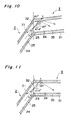
- the fiber optics device of the third embodiment is obtained by interposing, between the light-receiving surface 41 of the image pickup element 4 and the fiber optics device 1 described above, other fiber optics optical member assemblies for improving the optical coupling characteristics when using the fiber optics device 1.
- a fiber optics device 5 whose incident and exit surfaces are formed to intersect the optical axis of the optical fibers perpendicularly may be interposed between a fiber optics device 1 and a light-receiving surface 41, thereby improving the optical coupling characteristics between the fiber optics device 1 and the image pickup element 4.
- Fig. 13 As shown in Fig.
- the numerical aperture of the second optical member When the numerical aperture of the second optical member is set larger than that of the first optical member, light can become incident on the second optical member from the first optical member easily, and light can emerge from the exit surface of the second optical member in a wide range.
- the refractive index of the cores of the optical fibers of the first optical member is set to be equal to or higher than the refractive index of the cores of the optical fibers of the second optical member, when light propagates from the first optical member to the second optical member, it becomes incident on the second optical member without being totally reflected by the bonding portion between the first and second optical members. Therefore, an optical loss occurring at the bonding portion is prevented, and a clear optical image emerges from the exit surface.
- the inclination angle of the second optical member is set such that light incident on the second optical member from the first optical member at the maximum incident angle becomes incident on the boundary surface between the core and the cladding layer of the second optical member at a critical angle, light which is incident on the second optical member from the first optical member reliably propagates along the second optical member.
Applications Claiming Priority (3)
| Application Number | Priority Date | Filing Date | Title |
|---|---|---|---|
| JP100158/96 | 1996-04-22 | ||
| JP10015896A JP3839519B2 (ja) | 1996-04-22 | 1996-04-22 | ファイバ光学プレート |
| JP10015896 | 1996-04-22 |
Publications (2)
| Publication Number | Publication Date |
|---|---|
| EP0803745A1 true EP0803745A1 (de) | 1997-10-29 |
| EP0803745B1 EP0803745B1 (de) | 2004-06-16 |
Family
ID=14266517
Family Applications (1)
| Application Number | Title | Priority Date | Filing Date |
|---|---|---|---|
| EP97302740A Expired - Lifetime EP0803745B1 (de) | 1996-04-22 | 1997-04-22 | Faseroptisches Element |
Country Status (4)
| Country | Link |
|---|---|
| US (1) | US5903694A (de) |
| EP (1) | EP0803745B1 (de) |
| JP (1) | JP3839519B2 (de) |
| DE (1) | DE69729503T2 (de) |
Cited By (1)
| Publication number | Priority date | Publication date | Assignee | Title |
|---|---|---|---|---|
| WO2003019666A1 (fr) * | 2001-08-24 | 2003-03-06 | Hamamatsu Photonics K.K. | Dispositif d'imagerie |
Families Citing this family (7)
| Publication number | Priority date | Publication date | Assignee | Title |
|---|---|---|---|---|
| US6819687B1 (en) * | 1997-12-10 | 2004-11-16 | Nellcor Puritan Bennett Incorporated | Non-imaging optical corner turner |
| JPH11305082A (ja) * | 1998-02-23 | 1999-11-05 | Oki Electric Ind Co Ltd | 光結合モジュール |
| US6891926B1 (en) | 2000-08-09 | 2005-05-10 | Dalsa, Inc. | Fiber bundles for x-ray imaging |
| CN1491367A (zh) * | 2001-10-02 | 2004-04-21 | ���µ�����ҵ��ʽ���� | 图像检测装置 |
| JP2003240981A (ja) * | 2002-02-14 | 2003-08-27 | Hamamatsu Photonics Kk | ファイバ光学プレート及び凹凸パターン検出装置 |
| US7313708B2 (en) * | 2004-04-28 | 2007-12-25 | Microsoft Corporation | Interlocked plug and play with power management for operating systems |
| US20070098326A1 (en) * | 2005-11-01 | 2007-05-03 | Kuo Huei P | Light guide screen with louver device |
Citations (4)
| Publication number | Priority date | Publication date | Assignee | Title |
|---|---|---|---|---|
| US3402000A (en) * | 1964-09-10 | 1968-09-17 | Norman H. Crawford | Fiber optical image enlarger |
| US3874783A (en) * | 1972-08-02 | 1975-04-01 | American Optical Corp | Numerical aperture expansion in fiber optic devices |
| DE2634370A1 (de) * | 1975-08-02 | 1977-02-17 | Pilkington Perkin Elmer Ltd | Vorrichtung zum bilden eines optischen gelenks |
| US4099833A (en) * | 1974-03-08 | 1978-07-11 | Galileo Electro-Optics Corp. | Non-uniform fiber optic imaging system |
Family Cites Families (11)
| Publication number | Priority date | Publication date | Assignee | Title |
|---|---|---|---|---|
| US3906520A (en) * | 1973-08-03 | 1975-09-16 | Optics Technology Inc | Apparatus for producing a high contrast visible image from an object |
| GB1522520A (en) * | 1976-01-26 | 1978-08-23 | Secr Defence | Display panel constructions |
| US4932776A (en) * | 1987-11-05 | 1990-06-12 | Fingerprint Technology, Inc. | Fingerprint acquisition system |
| US5083874A (en) * | 1989-04-14 | 1992-01-28 | Nippon Telegraph And Telephone Corporation | Optical repeater and optical network using the same |
| CA2084103C (en) * | 1991-12-02 | 1999-07-27 | Keiji Sakai | A display apparatus |
| JP3045629B2 (ja) * | 1993-02-17 | 2000-05-29 | 三菱電機株式会社 | 凹凸パターン検出装置 |
| JP2806737B2 (ja) * | 1993-04-28 | 1998-09-30 | シャープ株式会社 | 表示装置 |
| JP3461591B2 (ja) * | 1993-11-02 | 2003-10-27 | 浜松ホトニクス株式会社 | ファイバー光学プレート |
| JPH08334636A (ja) * | 1995-06-05 | 1996-12-17 | Hamamatsu Photonics Kk | ファイバー光学プレート |
| JPH0943439A (ja) * | 1995-07-26 | 1997-02-14 | Hamamatsu Photonics Kk | ファイバー光学プレート |
| ATE235679T1 (de) * | 1998-08-03 | 2003-04-15 | Avu Ag Fuer Versorgungsunterne | Überwachung und nachrichtenübermittlung in rohren durch verbundglasfaserkabel und deren verlegung |
-
1996
- 1996-04-22 JP JP10015896A patent/JP3839519B2/ja not_active Expired - Lifetime
-
1997
- 1997-04-22 DE DE69729503T patent/DE69729503T2/de not_active Expired - Lifetime
- 1997-04-22 US US08/838,047 patent/US5903694A/en not_active Expired - Lifetime
- 1997-04-22 EP EP97302740A patent/EP0803745B1/de not_active Expired - Lifetime
Patent Citations (4)
| Publication number | Priority date | Publication date | Assignee | Title |
|---|---|---|---|---|
| US3402000A (en) * | 1964-09-10 | 1968-09-17 | Norman H. Crawford | Fiber optical image enlarger |
| US3874783A (en) * | 1972-08-02 | 1975-04-01 | American Optical Corp | Numerical aperture expansion in fiber optic devices |
| US4099833A (en) * | 1974-03-08 | 1978-07-11 | Galileo Electro-Optics Corp. | Non-uniform fiber optic imaging system |
| DE2634370A1 (de) * | 1975-08-02 | 1977-02-17 | Pilkington Perkin Elmer Ltd | Vorrichtung zum bilden eines optischen gelenks |
Non-Patent Citations (1)
| Title |
|---|
| H.TSUCHIYA ET.AL.: "Double eccentric connectors for optical fibers", APPLIED OPTICS., vol. 16, no. 5, May 1977 (1977-05-01), NEW YORK US, pages 1323 - 1331, XP002036658 * |
Cited By (4)
| Publication number | Priority date | Publication date | Assignee | Title |
|---|---|---|---|---|
| WO2003019666A1 (fr) * | 2001-08-24 | 2003-03-06 | Hamamatsu Photonics K.K. | Dispositif d'imagerie |
| EP1427020A1 (de) * | 2001-08-24 | 2004-06-09 | Hamamatsu Photonics K. K. | Abbildungseinrichtung |
| EP1427020A4 (de) * | 2001-08-24 | 2005-10-12 | Hamamatsu Photonics Kk | Abbildungseinrichtung |
| US7295736B2 (en) | 2001-08-24 | 2007-11-13 | Hamamatsu Photonics K.K. | Image pickup device |
Also Published As
| Publication number | Publication date |
|---|---|
| DE69729503D1 (de) | 2004-07-22 |
| EP0803745B1 (de) | 2004-06-16 |
| JP3839519B2 (ja) | 2006-11-01 |
| JPH09288223A (ja) | 1997-11-04 |
| DE69729503T2 (de) | 2005-06-30 |
| US5903694A (en) | 1999-05-11 |
Similar Documents
| Publication | Publication Date | Title |
|---|---|---|
| US5684905A (en) | Fiber optic plate for making pattern image incident on photosensor | |
| US5923806A (en) | Fiber optics device | |
| EP0192164B1 (de) | Optische Kupplungsvorrichtung | |
| EP0756243B1 (de) | Optische Faserplatte | |
| EP0670478B1 (de) | Mit Linse versehener Niveaufühler unter Verwendung eines optischen Punkts | |
| US5808729A (en) | Fiber-optic block and fingerprint detector using the same | |
| EP0821248B1 (de) | Faseroptisches Element, lichtempfangendes Element, und Vorrichtung zur Mustererfassung | |
| JP3461591B2 (ja) | ファイバー光学プレート | |
| EP0803745A1 (de) | Faseroptisches Element | |
| US20030095746A1 (en) | focusing fiber optic | |
| EP1001283B1 (de) | Optisches element,abbildeeinheit,abbildevorrichtung,strahlungsabbildungssensor und fingerabdruckanalysator unter verwendung derselben | |
| EP0846964B1 (de) | Optischer Glasenfaberblock | |
| JP2004240415A (ja) | 光ファイバタップ | |
| JPH08334636A (ja) | ファイバー光学プレート | |
| EP0177928B1 (de) | Lichtwellenleiter, insbesondere optische Faser | |
| US6219483B1 (en) | Optical device and imaging apparatus using the same | |
| JP3971440B2 (ja) | 表面凹凸形状検出装置 | |
| EP0141038A2 (de) | Bildübertragungsweg | |
| JP3884533B2 (ja) | ファイバ光学デバイス、受光部品及びパターン取得装置 | |
| EP1211530A2 (de) | Optische Kopplungsvorrichtung mit anisotropem lichtleitendem Element | |
| JPH10208022A (ja) | ファイバ光学プレート | |
| EP1008874B1 (de) | Optisches element und eine abbildungseinheit , abbildungsvorrichtung, strahlungsbildsensor und fingerabduck-analysator unter verwendung derselben | |
| JPS6030724Y2 (ja) | 光分配回路 | |
| JPH02171629A (ja) | 光導波路形温度センサ | |
| JPH10104444A (ja) | ファイバ光学デバイス、受光部品及びパターン取得装置 |
Legal Events
| Date | Code | Title | Description |
|---|---|---|---|
| PUAI | Public reference made under article 153(3) epc to a published international application that has entered the european phase |
Free format text: ORIGINAL CODE: 0009012 |
|
| AK | Designated contracting states |
Kind code of ref document: A1 Designated state(s): DE FR GB |
|
| 17P | Request for examination filed |
Effective date: 19980423 |
|
| 17Q | First examination report despatched |
Effective date: 20020712 |
|
| GRAP | Despatch of communication of intention to grant a patent |
Free format text: ORIGINAL CODE: EPIDOSNIGR1 |
|
| GRAS | Grant fee paid |
Free format text: ORIGINAL CODE: EPIDOSNIGR3 |
|
| GRAA | (expected) grant |
Free format text: ORIGINAL CODE: 0009210 |
|
| AK | Designated contracting states |
Kind code of ref document: B1 Designated state(s): DE FR GB |
|
| REG | Reference to a national code |
Ref country code: GB Ref legal event code: FG4D |
|
| REF | Corresponds to: |
Ref document number: 69729503 Country of ref document: DE Date of ref document: 20040722 Kind code of ref document: P |
|
| ET | Fr: translation filed | ||
| PLBE | No opposition filed within time limit |
Free format text: ORIGINAL CODE: 0009261 |
|
| STAA | Information on the status of an ep patent application or granted ep patent |
Free format text: STATUS: NO OPPOSITION FILED WITHIN TIME LIMIT |
|
| 26N | No opposition filed |
Effective date: 20050317 |
|
| REG | Reference to a national code |
Ref country code: FR Ref legal event code: PLFP Year of fee payment: 20 |
|
| PGFP | Annual fee paid to national office [announced via postgrant information from national office to epo] |
Ref country code: FR Payment date: 20160309 Year of fee payment: 20 |
|
| PGFP | Annual fee paid to national office [announced via postgrant information from national office to epo] |
Ref country code: DE Payment date: 20160419 Year of fee payment: 20 Ref country code: GB Payment date: 20160420 Year of fee payment: 20 |
|
| REG | Reference to a national code |
Ref country code: DE Ref legal event code: R071 Ref document number: 69729503 Country of ref document: DE |
|
| REG | Reference to a national code |
Ref country code: GB Ref legal event code: PE20 Expiry date: 20170421 |
|
| PG25 | Lapsed in a contracting state [announced via postgrant information from national office to epo] |
Ref country code: GB Free format text: LAPSE BECAUSE OF EXPIRATION OF PROTECTION Effective date: 20170421 |