EP0803675B1 - Rohrverbindung, insbesondere zum Verbinden zweier rohrförmiger Rumpfteile eines Flugkörpers - Google Patents
Rohrverbindung, insbesondere zum Verbinden zweier rohrförmiger Rumpfteile eines Flugkörpers Download PDFInfo
- Publication number
- EP0803675B1 EP0803675B1 EP97106217A EP97106217A EP0803675B1 EP 0803675 B1 EP0803675 B1 EP 0803675B1 EP 97106217 A EP97106217 A EP 97106217A EP 97106217 A EP97106217 A EP 97106217A EP 0803675 B1 EP0803675 B1 EP 0803675B1
- Authority
- EP
- European Patent Office
- Prior art keywords
- tube
- circumferential
- sections
- tube connection
- connection according
- Prior art date
- Legal status (The legal status is an assumption and is not a legal conclusion. Google has not performed a legal analysis and makes no representation as to the accuracy of the status listed.)
- Expired - Lifetime
Links
- 230000002093 peripheral effect Effects 0.000 description 12
- 230000007704 transition Effects 0.000 description 2
- 238000005452 bending Methods 0.000 description 1
- 238000010276 construction Methods 0.000 description 1
- 238000004519 manufacturing process Methods 0.000 description 1
Images
Classifications
-
- F—MECHANICAL ENGINEERING; LIGHTING; HEATING; WEAPONS; BLASTING
- F16—ENGINEERING ELEMENTS AND UNITS; GENERAL MEASURES FOR PRODUCING AND MAINTAINING EFFECTIVE FUNCTIONING OF MACHINES OR INSTALLATIONS; THERMAL INSULATION IN GENERAL
- F16L—PIPES; JOINTS OR FITTINGS FOR PIPES; SUPPORTS FOR PIPES, CABLES OR PROTECTIVE TUBING; MEANS FOR THERMAL INSULATION IN GENERAL
- F16L21/00—Joints with sleeve or socket
- F16L21/06—Joints with sleeve or socket with a divided sleeve or ring clamping around the pipe ends
-
- F—MECHANICAL ENGINEERING; LIGHTING; HEATING; WEAPONS; BLASTING
- F16—ENGINEERING ELEMENTS AND UNITS; GENERAL MEASURES FOR PRODUCING AND MAINTAINING EFFECTIVE FUNCTIONING OF MACHINES OR INSTALLATIONS; THERMAL INSULATION IN GENERAL
- F16L—PIPES; JOINTS OR FITTINGS FOR PIPES; SUPPORTS FOR PIPES, CABLES OR PROTECTIVE TUBING; MEANS FOR THERMAL INSULATION IN GENERAL
- F16L21/00—Joints with sleeve or socket
- F16L21/08—Joints with sleeve or socket with additional locking means
-
- F—MECHANICAL ENGINEERING; LIGHTING; HEATING; WEAPONS; BLASTING
- F16—ENGINEERING ELEMENTS AND UNITS; GENERAL MEASURES FOR PRODUCING AND MAINTAINING EFFECTIVE FUNCTIONING OF MACHINES OR INSTALLATIONS; THERMAL INSULATION IN GENERAL
- F16L—PIPES; JOINTS OR FITTINGS FOR PIPES; SUPPORTS FOR PIPES, CABLES OR PROTECTIVE TUBING; MEANS FOR THERMAL INSULATION IN GENERAL
- F16L23/00—Flanged joints
- F16L23/04—Flanged joints the flanges being connected by members tensioned in the radial plane
-
- Y—GENERAL TAGGING OF NEW TECHNOLOGICAL DEVELOPMENTS; GENERAL TAGGING OF CROSS-SECTIONAL TECHNOLOGIES SPANNING OVER SEVERAL SECTIONS OF THE IPC; TECHNICAL SUBJECTS COVERED BY FORMER USPC CROSS-REFERENCE ART COLLECTIONS [XRACs] AND DIGESTS
- Y10—TECHNICAL SUBJECTS COVERED BY FORMER USPC
- Y10S—TECHNICAL SUBJECTS COVERED BY FORMER USPC CROSS-REFERENCE ART COLLECTIONS [XRACs] AND DIGESTS
- Y10S285/00—Pipe joints or couplings
- Y10S285/913—Interdigitating
Definitions
- the invention relates to a pipe connection, in particular for connecting two tubular fuselage parts one Missile.
- the invention has for its object a high-strength and to create highly rigid pipe connections.
- the pipe connection should be detachable.
- the pipe joint should enable easy assembly. Costs and Manufacturing effort should be low.
- the construction volume should be small.
- the pipe connection is said to be a large one Leave free cross section. Enlargements of the Outside diameter through the pipe connection should be avoided become.
- the pipe connection should continue to be free of play.
- an "asymmetrical Radial screw connection” provided.
- Such an asymmetrical Radial screwing has the advantage that the two Pipe parts perpendicular to the dividing line of the two Circumferential sections freely in a small area to each other can be moved. This creates at Do not screw large radial internal stresses. The allows an excellent form fit. When the asymmetrical radial screw connection is loaded with a bending moment, the force is mainly over the Transfer screws.
- Embodiments of the invention are the subject of Subclaims.
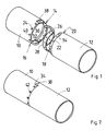
- 10 denotes a first pipe part.
- the first pipe part 10 is intended to be connected to a second pipe part 12 get connected.
- the pipe parts 10 and 12 are tubular Parts of the fuselage of a missile.
- the pipe part 10 has along the edge to be connected a first, extending over approximately 180 ° Circumferential section 14 one against a second Circumferential section 16 reduced outer diameter.
- the tube part 12 has along the edge to be connected a first, extending over approximately 180 ° Circumferential section 18 one against a second Circumferential section 20 reduced outer diameter.
- the tube part 12 is however with its edge part in relation to the tube part 10 by 180 ° around the Pipe axis twisted.
- the pipe parts 10 and 12 are then like this put together that of each tube part 10 or 12 of Circumferential section 14 or 18 with a smaller outer diameter in a peripheral section 16 or 20 with a larger Outer diameter of the other tube part 21 or 10 is inserted.
- the peripheral sections 14, 16, 18 and 20 are with radial bores 22 and 24 for Provide connecting screws.
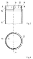
- ring sections 26 and 28 respectively Threaded bores 30 arranged.
- the threaded holes 30 align with the radial bores 22 and 24 of the Circumferential sections 14, 20 and 18, 16.
- the ring sections 26 and 28 each extend over 180 °. Here lies the Ring section 26 in the region of the peripheral sections 14 and 20.
- the ring section 28 is in the range of Circumferential sections 18 and 16.
- a longitudinal slot 32 or 34 formed between the peripheral sections 14 and 16 or 18 and 20 of a tube part 10 or 12 between the peripheral sections 14 and 16 or 18 and 20 of a tube part 10 or 12.
- the longitudinal slot 32 and 34 is a between the peripheral sections 18 and 20 or 14 and 16 the other tube part 12 or 10 formed step transition 36 or 38 insertable.
- peripheral sections 16 and 20 with larger Outside diameters then indicate on the outside the radial bores 24 counterbores 40 for screw heads 42 on.
Landscapes
- Engineering & Computer Science (AREA)
- General Engineering & Computer Science (AREA)
- Mechanical Engineering (AREA)
- Mutual Connection Of Rods And Tubes (AREA)
Description
- Fig.1
- ist eine perspektivische Darstellung zweier durch eine asymmetrische Radialverschraubung zu verbindender Rohrteile im auseinandergezogenen Zustand.
- Fig.2
- ist eine perspektivische Darstellung der beiden Rohrteile im verbundenen Zustand.
- Fig.3
- zeigt einen Längsschnitt eines Endabschnitts eines der Rohrteile von Fig.1 und 2.
- Fig.4
- zeigt einen Querschnitt des Endabschnitts von Fig.3.
Claims (8)
- Rohrverbindung zum Verbinden zweier Rohrteile (10, 12) insbesondere zum Verbinden zweier rohrförmiger Rumpfteile eines Flugkörpers, wobei(a) jeder der Rohrteile (10,12) längs des mit dem anderen Rohrteil (12 bzw. 10) zu verbindenden Randes auf einem ersten Umfangsabschnitt (14 bzw. 18) einen gegenüber einem zweiten Umfangsabschnitt (16 bzw. 20) verminderten Außendurchmesser aufweist, der abzüglich einer Zusammenfüge-Toleranz dem Innendurchmesser des zweiten Umfangsabschnitts (16 bzw. 18) entspricht,(b) die Rohrteile (10,12) so zusammengefügt sind, daß von jedem Rohrteil (10,12) der Umfangsabschnitt (14,18) mit geringerem Außendurchmesser in einen Umfangsabschnitt (16,20) mit größerem Außendurchmesser des jeweils anderen Rohrteils (12 bzw. 10) eingeschoben ist und(c) die Umfangsabschnitte (14, 16;18,20) mit radialen Bohrungen (22,24) für Verbindungsschrauben versehen sind.
- Rohrverbindung nach Anspruch 1, dadurch gekennzeichnet, daß innerhalb der so zusammengefügten Umfangsabschnitte (14,20;18,16) Ringabschnitte (26,28) mit Gewindebohrungen (30) angeordnet sind, die mit den radialen Bohrungen (22,24) der Umfangsabschnitte (14,20;18,16) fluchten.
- Rohrverbindung nach Anspruch 2, dadurch gekennzeichnet, daß(a) jeder der Umfangsabschnitte (14,16;18,20) sich über im wesentlichen 180° erstreckt,(b) die Rohrteile (10,12) an ihren zu verbindenden Enden im wesentlichen übereinstimmend ausgebildet und(c) mit ihren Umfangsabschnitten (14,16;18,20) um 180° zueinander winkelversetzt zusammengefügt sind.
- Rohrverbindung nach Anspruch 3, dadurch gekennzeichnet, daß zwischen den Umfangsabschnitten (14,16;18,20) eines Rohrteils (10,12) jeweils ein Längsschlitz (32,34) gebildet ist, in welchen ein zwischen den Umfangsabschnitten (18,20;14,16) des anderen Rohrteils (12,10) gebildeter Stufenübergang (38) einschiebbar ist.
- Rohrverbindung nach Anspruch 4, dadurch gekennzeichnet, daß an jedem der Rohrteile ein Längsschlitz (32,34) und diametral dazu gegenüberliegend ein Stufenübergang (38) vorgesehen ist
- Rohrverbindung nach einem der Ansprüche 3 bis 5, dadurch gekennzeichnet, daß die Ringabschnitte (26,28) sich jeweils über etwa 180° erstrecken.
- Rohrverbindung nach Anspruch 6, dadurch gekennzeichnet, daß jeder Ringabschnitt (26,28) sich über den Winkelbereich eines zugehörigen Umfangsabschnitts (14,16;18,20) erstreckt.
- Rohrverbindung nach einem der Ansprüche 1 bis 7, dadurch gekennzeichnet, daß die Umfangsabschnitte (16,20) mit größerem Außendurchmesser auf der Außenseite anschließend an die radialen Bohrungen (24) Senkungen (40) für Schraubenköpfe (42) aufweisen.
Applications Claiming Priority (2)
| Application Number | Priority Date | Filing Date | Title |
|---|---|---|---|
| DE19615716 | 1996-04-22 | ||
| DE19615716A DE19615716A1 (de) | 1996-04-22 | 1996-04-22 | Rohrverbindung, insbesondere zum Verbinden zweier rohrförmiger Rumpfteile eines Flugkörpers |
Publications (3)
| Publication Number | Publication Date |
|---|---|
| EP0803675A2 EP0803675A2 (de) | 1997-10-29 |
| EP0803675A3 EP0803675A3 (de) | 1998-09-30 |
| EP0803675B1 true EP0803675B1 (de) | 2000-09-20 |
Family
ID=7791892
Family Applications (1)
| Application Number | Title | Priority Date | Filing Date |
|---|---|---|---|
| EP97106217A Expired - Lifetime EP0803675B1 (de) | 1996-04-22 | 1997-04-16 | Rohrverbindung, insbesondere zum Verbinden zweier rohrförmiger Rumpfteile eines Flugkörpers |
Country Status (3)
| Country | Link |
|---|---|
| US (1) | US5876072A (de) |
| EP (1) | EP0803675B1 (de) |
| DE (2) | DE19615716A1 (de) |
Families Citing this family (11)
| Publication number | Priority date | Publication date | Assignee | Title |
|---|---|---|---|---|
| DE19735452C2 (de) * | 1997-08-16 | 1999-07-22 | Bodenseewerk Geraetetech | Rohrverbindung, insbesondere zum Verbinden zweier rohrförmiger Rumpfteile eines Flugkörpers |
| WO2005001323A1 (en) * | 2003-06-27 | 2005-01-06 | Lindab Ab | Assembly system for a pipe coupling |
| US20040262922A1 (en) * | 2003-06-27 | 2004-12-30 | Lindab Ab | Assembly system for a pipe coupling |
| DE102006060360B8 (de) * | 2006-12-20 | 2010-09-30 | Airbus Deutschland Gmbh | Rumpfsektion zur Bildung einer Rumpfzelle eines Flugzeugs |
| DE102009021369A1 (de) * | 2009-05-12 | 2010-11-18 | Airbus Operations Gmbh | Verfahren zur Herstellung eines Flugzeugrumpfes und Flugzeugrumpf |
| US8708601B2 (en) | 2010-02-16 | 2014-04-29 | Jensen Enterprises, Inc. | Box culvert |
| CN102765472B (zh) * | 2012-07-31 | 2015-03-11 | 江西洪都航空工业集团有限责任公司 | 一种飞机机身模块化连接装置 |
| DE102013102812B4 (de) * | 2013-03-19 | 2017-01-26 | Airbus Operations Gmbh | Rumpfstruktur für ein Verkehrsmittel, Verkehrsmittel und Verfahren zum Herstellen einer Rumpfstruktur für ein Verkehrsmittel |
| CN107074340B (zh) * | 2016-04-01 | 2019-07-30 | 深圳市大疆创新科技有限公司 | 用于无人飞行器的机架连接组件及无人飞行器 |
| CN111332492B (zh) * | 2020-03-06 | 2021-06-01 | 北京机电工程研究所 | 一种飞行器舱段无缆对接装置及其对接方法 |
| USD977044S1 (en) | 2020-05-11 | 2023-01-31 | Gary Kemp | Inflatable zeotrope ball |
Family Cites Families (6)
| Publication number | Priority date | Publication date | Assignee | Title |
|---|---|---|---|---|
| US1639999A (en) * | 1926-02-06 | 1927-08-23 | Omar R Humphreys | Sewer pipe |
| US2710763A (en) * | 1951-02-24 | 1955-06-14 | Bendix Aviat Corp | Quick disconnect mounting |
| US2945704A (en) * | 1957-07-23 | 1960-07-19 | Hughes Aircraft Co | Nose section-quick disconnect |
| DE1911697C3 (de) * | 1969-03-03 | 1974-03-21 | 6600 Saarbruecken | Lösbare Verbindung für der Bohrpfahlherstellung dienende Bohrrohre |
| US4348956A (en) * | 1980-08-29 | 1982-09-14 | The United States Of America As Represented By The Secretary Of The Army | Artillery shell comprising two sections having complementary coupling members for connecting the sections together |
| US5290974A (en) * | 1993-03-12 | 1994-03-01 | Arvin Industries, Inc. | Tab and notch locator for exhaust systems |
-
1996
- 1996-04-22 DE DE19615716A patent/DE19615716A1/de not_active Withdrawn
-
1997
- 1997-04-16 EP EP97106217A patent/EP0803675B1/de not_active Expired - Lifetime
- 1997-04-16 DE DE59702368T patent/DE59702368D1/de not_active Expired - Fee Related
- 1997-04-21 US US08/845,028 patent/US5876072A/en not_active Expired - Fee Related
Also Published As
| Publication number | Publication date |
|---|---|
| DE19615716A1 (de) | 1997-10-23 |
| EP0803675A2 (de) | 1997-10-29 |
| DE59702368D1 (de) | 2000-10-26 |
| EP0803675A3 (de) | 1998-09-30 |
| US5876072A (en) | 1999-03-02 |
Similar Documents
| Publication | Publication Date | Title |
|---|---|---|
| DE4310510C2 (de) | Faltenbalg | |
| EP0803675B1 (de) | Rohrverbindung, insbesondere zum Verbinden zweier rohrförmiger Rumpfteile eines Flugkörpers | |
| DE60116987T2 (de) | Vorrichtung zum Zentrieren eines Rohres in einer Turbinenwelle | |
| DE19742361C2 (de) | Elastischer Gelenkkörper | |
| EP0898146B1 (de) | Verbindung zweier rohrförmiger Rumpfteile eines Flugkörpers | |
| EP2646625B1 (de) | Kupplung, insbesondere für das verbinden von ankerstangen | |
| DE10304156A1 (de) | Gegenbahngelenk mit verbessertem Käfig | |
| EP0859212A2 (de) | Spannring zum Verbinden von zylinderförmigen Baugruppen von Flugkörpern | |
| EP0575727A1 (de) | Rohrgelenk | |
| DE3027432C2 (de) | ||
| DE10349783A1 (de) | Radiallagerung für eine Antriebswelle von Fahrzeugen | |
| DE102005026148B4 (de) | Steckverbinderkupplung | |
| DE19529901A1 (de) | Knochenschraube | |
| EP1018603A2 (de) | Antriebswelle | |
| DE2517050C2 (de) | Rohrverbindung | |
| DE10149017C2 (de) | Lösbares Passverbindungselement für ein Bauteil, mit einer Passschraube und einem Stützring | |
| DE2904776C2 (de) | ||
| DE102016000291A1 (de) | Verfahren zum Herstellen einer Flanschverbindung, Verwendung, Flanschverbindung und Windenergieanlage | |
| EP0833018A2 (de) | Gelenkvorrichtung | |
| DE3104518A1 (de) | Anschlussarmatur | |
| DE3143485C2 (de) | ||
| DE3606073C2 (de) | Drehgelenk | |
| DE4140311A1 (de) | Wellenkupplungselement | |
| DE102017209004B4 (de) | Gleichlaufgelenk in Faserverbundbauweise | |
| DE4303901C2 (de) | Gleichlaufdrehgelenk |
Legal Events
| Date | Code | Title | Description |
|---|---|---|---|
| PUAI | Public reference made under article 153(3) epc to a published international application that has entered the european phase |
Free format text: ORIGINAL CODE: 0009012 |
|
| AK | Designated contracting states |
Kind code of ref document: A2 Designated state(s): DE FR GB IT |
|
| PUAL | Search report despatched |
Free format text: ORIGINAL CODE: 0009013 |
|
| AK | Designated contracting states |
Kind code of ref document: A3 Designated state(s): DE FR GB IT |
|
| 17P | Request for examination filed |
Effective date: 19980908 |
|
| GRAG | Despatch of communication of intention to grant |
Free format text: ORIGINAL CODE: EPIDOS AGRA |
|
| GRAG | Despatch of communication of intention to grant |
Free format text: ORIGINAL CODE: EPIDOS AGRA |
|
| GRAH | Despatch of communication of intention to grant a patent |
Free format text: ORIGINAL CODE: EPIDOS IGRA |
|
| 17Q | First examination report despatched |
Effective date: 20000306 |
|
| GRAH | Despatch of communication of intention to grant a patent |
Free format text: ORIGINAL CODE: EPIDOS IGRA |
|
| GRAA | (expected) grant |
Free format text: ORIGINAL CODE: 0009210 |
|
| AK | Designated contracting states |
Kind code of ref document: B1 Designated state(s): DE FR GB IT |
|
| REF | Corresponds to: |
Ref document number: 59702368 Country of ref document: DE Date of ref document: 20001026 |
|
| GBT | Gb: translation of ep patent filed (gb section 77(6)(a)/1977) |
Effective date: 20001024 |
|
| ET | Fr: translation filed | ||
| ITF | It: translation for a ep patent filed | ||
| PLBE | No opposition filed within time limit |
Free format text: ORIGINAL CODE: 0009261 |
|
| STAA | Information on the status of an ep patent application or granted ep patent |
Free format text: STATUS: NO OPPOSITION FILED WITHIN TIME LIMIT |
|
| 26N | No opposition filed | ||
| REG | Reference to a national code |
Ref country code: GB Ref legal event code: IF02 |
|
| PGFP | Annual fee paid to national office [announced via postgrant information from national office to epo] |
Ref country code: FR Payment date: 20030318 Year of fee payment: 7 |
|
| PGFP | Annual fee paid to national office [announced via postgrant information from national office to epo] |
Ref country code: GB Payment date: 20030403 Year of fee payment: 7 |
|
| PGFP | Annual fee paid to national office [announced via postgrant information from national office to epo] |
Ref country code: DE Payment date: 20030626 Year of fee payment: 7 |
|
| PG25 | Lapsed in a contracting state [announced via postgrant information from national office to epo] |
Ref country code: GB Free format text: LAPSE BECAUSE OF NON-PAYMENT OF DUE FEES Effective date: 20040416 |
|
| PG25 | Lapsed in a contracting state [announced via postgrant information from national office to epo] |
Ref country code: DE Free format text: LAPSE BECAUSE OF NON-PAYMENT OF DUE FEES Effective date: 20041103 |
|
| GBPC | Gb: european patent ceased through non-payment of renewal fee |
Effective date: 20040416 |
|
| PG25 | Lapsed in a contracting state [announced via postgrant information from national office to epo] |
Ref country code: FR Free format text: LAPSE BECAUSE OF NON-PAYMENT OF DUE FEES Effective date: 20041231 |
|
| REG | Reference to a national code |
Ref country code: FR Ref legal event code: ST |
|
| PG25 | Lapsed in a contracting state [announced via postgrant information from national office to epo] |
Ref country code: IT Free format text: LAPSE BECAUSE OF NON-PAYMENT OF DUE FEES;WARNING: LAPSES OF ITALIAN PATENTS WITH EFFECTIVE DATE BEFORE 2007 MAY HAVE OCCURRED AT ANY TIME BEFORE 2007. THE CORRECT EFFECTIVE DATE MAY BE DIFFERENT FROM THE ONE RECORDED. Effective date: 20050416 |