EP0803389B1 - Vehicle door - Google Patents
Vehicle door Download PDFInfo
- Publication number
- EP0803389B1 EP0803389B1 EP97106226A EP97106226A EP0803389B1 EP 0803389 B1 EP0803389 B1 EP 0803389B1 EP 97106226 A EP97106226 A EP 97106226A EP 97106226 A EP97106226 A EP 97106226A EP 0803389 B1 EP0803389 B1 EP 0803389B1
- Authority
- EP
- European Patent Office
- Prior art keywords
- carrier
- vehicle door
- door
- hinge
- profile
- Prior art date
- Legal status (The legal status is an assumption and is not a legal conclusion. Google has not performed a legal analysis and makes no representation as to the accuracy of the status listed.)
- Expired - Lifetime
Links
Images

Classifications
-
- B—PERFORMING OPERATIONS; TRANSPORTING
- B60—VEHICLES IN GENERAL
- B60J—WINDOWS, WINDSCREENS, NON-FIXED ROOFS, DOORS, OR SIMILAR DEVICES FOR VEHICLES; REMOVABLE EXTERNAL PROTECTIVE COVERINGS SPECIALLY ADAPTED FOR VEHICLES
- B60J5/00—Doors
- B60J5/04—Doors arranged at the vehicle sides
- B60J5/0401—Upper door structure
- B60J5/0404—Outside rear view mirror support
-
- B—PERFORMING OPERATIONS; TRANSPORTING
- B60—VEHICLES IN GENERAL
- B60J—WINDOWS, WINDSCREENS, NON-FIXED ROOFS, DOORS, OR SIMILAR DEVICES FOR VEHICLES; REMOVABLE EXTERNAL PROTECTIVE COVERINGS SPECIALLY ADAPTED FOR VEHICLES
- B60J5/00—Doors
- B60J5/04—Doors arranged at the vehicle sides
- B60J5/0412—Lower door structure
-
- B—PERFORMING OPERATIONS; TRANSPORTING
- B60—VEHICLES IN GENERAL
- B60J—WINDOWS, WINDSCREENS, NON-FIXED ROOFS, DOORS, OR SIMILAR DEVICES FOR VEHICLES; REMOVABLE EXTERNAL PROTECTIVE COVERINGS SPECIALLY ADAPTED FOR VEHICLES
- B60J5/00—Doors
- B60J5/04—Doors arranged at the vehicle sides
- B60J5/0463—Conceptual assembling of door, i.e. how door frame parts should be fitted together to form door
- B60J5/0466—Conceptual assembling of door, i.e. how door frame parts should be fitted together to form door using cast parts
-
- B—PERFORMING OPERATIONS; TRANSPORTING
- B60—VEHICLES IN GENERAL
- B60J—WINDOWS, WINDSCREENS, NON-FIXED ROOFS, DOORS, OR SIMILAR DEVICES FOR VEHICLES; REMOVABLE EXTERNAL PROTECTIVE COVERINGS SPECIALLY ADAPTED FOR VEHICLES
- B60J5/00—Doors
- B60J5/04—Doors arranged at the vehicle sides
- B60J5/048—Doors arranged at the vehicle sides characterised by the material
- B60J5/0483—Doors arranged at the vehicle sides characterised by the material lightweight metal, e.g. aluminum, magnesium
Definitions
- the invention relates to a vehicle door with an outer wall, an inner wall and a door frame according to the features of Preamble of claim 1.
- a vehicle door is known from the generic EP 0 274 985 B1, at which is arranged between the outer wall and the inner wall
- Door frame essentially from a one-piece casting consists of both the lock and the hinge carrier as well as a lower flange profile connecting the two beams includes.
- Between the lock and hinge bracket is also arranged at least one cross strut that there is an extruded profile, and both a stiffening of the door frame as well as for receiving door parts can serve.
- This cross strut should be from the bottom chord profile have a predetermined distance and is in the embodiment shown in Fig. 1 of EP 0 274 985 B1 approximately in the lower third of the vehicle door.
- a disadvantage of these known vehicle doors is, among other things, that they are only very expensive to manufacture. On the one hand a relatively large molded part must be cast, which usually only for a very specific vehicle type is usable. On the other hand, to reinforce the door frame additional cross struts are made that at the same time improve the impact behavior of the vehicle door should. Because it has been shown that one as a casting trained lower flange profile for higher loads (side impact) breaks relatively quickly because on the one hand the elongation at break of die-cast parts is low and on the other hand in the event of a side impact, the load in the area of the lower flange profile is particularly high.
- a disadvantage of such a door structure is both the high Weight of the door due to the steel sheets used as well the relatively complex manufacture of such doors.
- the invention lies in the Task based on specifying a vehicle door that is inexpensive is producible, has a low weight and a has good impact behavior.
- the invention is essentially based on the idea Lock and hinge carrier as well as the lower flange profile first to manufacture as separate components and then to one frame-shaped self-supporting door frames together connect to which the inner and outer walls can be attached is.
- lock and hinge supports each around a light metal die-cast part and at the lower flange profile around an extruded, stamped or rolled profile part.
- the die-casting mold be designed such that the hinge bracket already has hinges on the door and / or has a holder for the mirror triangle.
- the lock carrier can already be made with an integrated lock plate become.
- Both parts can have integrated mounting domes for screws or clips etc. as well as with stiffening ribs be poured.
- the separate production of the two die-cast parts is due the small dimensions are procedurally simple and allows the use of these parts to build different ones Door frames, for example for different vehicle doors Variants of a vehicle model.
- these carriers are preferably made after the vacuum casting, Thixocasting or thixomoulding process.
- the lower flange profile as an extruded part or as a punched or rolled profile is sufficient Elongation at break guaranteed in the event of a side impact.
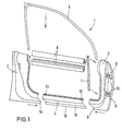
- 1 and 2 denotes a door frame, the essentially consists of a lock bracket 2, a hinge bracket 3, a lower flange profile 4 and a window frame 5 and a window shaft profile 6 is composed. How 1 can be removed, for example, a window guide profile 7 to guide the disc, not shown be provided.
- the lock carrier 2 and the hinge carrier 3 are concerned are aluminum die-cast parts, preferably with the help of the vacuum casting process, so that these parts a corresponding high ductility and weldability exhibit.
- the wall thickness of the die-cast parts 2, 3 is dimensioned such that that they have a relatively large diameter in areas has in which the intended use of Door high forces can occur. This is for example with the hinge bracket 3 in the area 8 of the hinge connection the case. In contrast, the die-cast parts 2, 3 in Areas 9, 10 in which flanged edges for flanging the outside or inside wall, not shown, are essential thinner.
- the hinges on the door are 11 integrated directly into the hinge bracket 3.
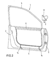
- the lower flange profile 4 is an extruded aluminum profile, which on its the lock carrier 2 and the hinge bracket 3 facing ends 12, 13 with these Share with the aid of punch rivets 14 (Fig.2) is connected. On its underside 15 there is also the lower flange profile 4 provided with a flanged edge 16.
- the invention is of course not based on the above described embodiment limited. So they can Beams 2, 3 and 4 additionally in the edge areas where they are riveted, also glued to good Ensure sealing against condensation water.
- FIG. 3 A corresponding embodiment is shown in Figure 3.
- the corresponding hinge bracket is 30 designated. Below the dashed door sill 18 follows the hinge bracket 30 similar to that in FIG the Fig.1 and 2. illustrated embodiment- in essentially the inner door contour. In the area above the On the other hand, the door parapet 18 is the hinge bracket 30 to the outside broken and forms here in a predeterminable region 19 part of the outer surface of the door. With 20 is the outer skin sheet in Figure 3 the corresponding door.
Landscapes
- Engineering & Computer Science (AREA)
- Mechanical Engineering (AREA)
- Body Structure For Vehicles (AREA)
Description
Die Erfindung betrifft eine Fahrzeugtür mit einer Außenwand,
einer Innenwand und einem Türgerippe gemäß den Merkmalen des
Oberbegriffs des Anspruchs 1.The invention relates to a vehicle door with an outer wall,
an inner wall and a door frame according to the features of
Preamble of
Aus der gattungsbildenden EP 0 274 985 B1 ist eine Fahrzeugtür bekannt, bei welcher das zwischen der Außenwand und der Innenwand angeordnete Türgerippe im wesentlichen aus einem einteiligen Gußteil besteht, welches sowohl den Schloß- und den Scharnierträger als auch ein die beiden Träger miteinander verbindendes Untergurtprofil umfaßt. Zwischen Schloß- und Scharnierträger ist ferner mindestens eine Querstrebe angeordnet, die aus einem Strangpreßprofil besteht, und die sowohl eine Versteifung des Türgerippes bewirkt als auch zur Aufnahme von Türteilen dienen kann. Diese Querstrebe soll von dem Untergurtprofil einen vorgegebenen Abstand besitzen und befindet sich in dem in Fig.1 der EP 0 274 985 B1 dargestellten Ausführungsbeispiel etwa im unteren Drittel der Fahrzeugtür. A vehicle door is known from the generic EP 0 274 985 B1, at which is arranged between the outer wall and the inner wall Door frame essentially from a one-piece casting consists of both the lock and the hinge carrier as well as a lower flange profile connecting the two beams includes. Between the lock and hinge bracket is also arranged at least one cross strut that there is an extruded profile, and both a stiffening of the door frame as well as for receiving door parts can serve. This cross strut should be from the bottom chord profile have a predetermined distance and is in the embodiment shown in Fig. 1 of EP 0 274 985 B1 approximately in the lower third of the vehicle door.
Nachteilig ist bei diesen bekannten Fahrzeugtüren unter anderem, daß sie nur sehr kostenintensiv herstellbar sind. Einerseits muß ein relativ großes Formteil gegossen werden, welches in der Regel nur für einen ganz bestimmten Fahrzeugtyp verwendbar ist. Andererseits müssen zur Versteifung des Türgerippes zusätzliche Querstreben hergestellt werden, die gleichzeitig das Aufprallverhalten der Fahrzeugtür verbessern sollen. Denn es hat sich gezeigt, daß ein als Gußteil ausgebildetes Untergurtprofil bei höheren Beanspruchungen (seitlicher Aufprall) relativ schnell bricht, weil einerseits die Bruchdehnung von Druckgußteilen gering ist und andererseits bei einem seitlichen Aufprall die Belastung im Bereich des Untergurtprofiles besonders hoch ist.A disadvantage of these known vehicle doors is, among other things, that they are only very expensive to manufacture. On the one hand a relatively large molded part must be cast, which usually only for a very specific vehicle type is usable. On the other hand, to reinforce the door frame additional cross struts are made that at the same time improve the impact behavior of the vehicle door should. Because it has been shown that one as a casting trained lower flange profile for higher loads (side impact) breaks relatively quickly because on the one hand the elongation at break of die-cast parts is low and on the other hand in the event of a side impact, the load in the area of the lower flange profile is particularly high.
Aus der EP 0 476 351 B1 ist ferner eine Fahrzeugtür in Stahl-Blechbauweise bekannt, bei der an einem relativ steifen Türinnenblech ein entsprechender aus separatem Schloß- und Scharnierträger bestehender Aggregateträger angeschweißt ist. Die beiden Trägerteile werden oberseitig durch eine profilierte stabförmige Fensterschachtverstärkung miteinander verbunden.From EP 0 476 351 B1 there is also a vehicle door in sheet steel construction known in the case of a relatively rigid inner door panel a corresponding from separate lock and Hinge bracket of existing subframe is welded on. The two carrier parts are profiled on the top side rod-shaped window shaft reinforcement interconnected.
Nachteilig bei einem derartigen Türaufbau ist sowohl das hohe Gewicht der Tür aufgrund der verwendeten Stahlbleche als auch die relativ aufwendige Herstellung derartiger Türen.A disadvantage of such a door structure is both the high Weight of the door due to the steel sheets used as well the relatively complex manufacture of such doors.
Ausgehend von der EP 0 274 985 B1 liegt der Erfindung die Aufgabe zugrunde, eine Fahrzeugtür anzugeben, die kostengünstig herstellbar ist, ein geringes Gewicht aufweist und ein gutes Aufprallverhalten besitzt.Starting from EP 0 274 985 B1, the invention lies in the Task based on specifying a vehicle door that is inexpensive is producible, has a low weight and a has good impact behavior.
Diese Aufgabe wird erfindungsgemäß durch die Merkmale des
kennzeichnenden Teils des Anspruchs 1 gelöst. Weitere
besonders vorteilhafte Ausgestaltungen der Erfindung offenbaren
die Unteransprüche.This object is achieved by the features of
characterizing part of
Die Erfindung beruht im wesentlichen auf dem Gedanken, Schloß- und Scharnierträger sowie das Untergurtprofil zunächst als separate Bauteile herzustellen und dann zu einem rahmenförmigen selbsttragenden Türgerippe miteinander zu verbinden, an welchem die Innen- und die Außenwand befestigbar ist. Dabei handelt es sich bei dem Schloß- und dem Scharnierträger jeweils um ein Leichtmetall-Druckgußteil und bei dem Untergurtprofil um ein Strangpreß-, Stanz- oder Rollprofilteil.The invention is essentially based on the idea Lock and hinge carrier as well as the lower flange profile first to manufacture as separate components and then to one frame-shaped self-supporting door frames together connect to which the inner and outer walls can be attached is. These are the lock and hinge supports each around a light metal die-cast part and at the lower flange profile around an extruded, stamped or rolled profile part.
Durch die Verwendung von Druckgußteilen ist es möglich, sowohl in den Schloß- als auch in den Scharnierträger eine Vielzahl von Funktionsteilen zu integrieren. So kann beispielsweise die Druckgußform derart ausgestaltet sein, daß der Scharnierträger bereits türseitige Scharniere und/oder eine Aufnahme für das Spiegeldreieck besitzt. Der Schloßträger kann bereits mit einer integrierten Schloßplatte hergestellt werden. Beide Teile können mit integrierten Befestigungsdomen für Schrauben oder Clipse etc. sowie mit Versteifungsrippen gegossen werden.By using die cast parts it is possible to both in the lock as well as in the hinge bracket Integrate a variety of functional parts. For example the die-casting mold be designed such that the hinge bracket already has hinges on the door and / or has a holder for the mirror triangle. The lock carrier can already be made with an integrated lock plate become. Both parts can have integrated mounting domes for screws or clips etc. as well as with stiffening ribs be poured.
Die separate Herstellung der beiden Druckgußteile ist aufgrund der geringen Abmessungen verfahrenstechnisch einfach und erlaubt die Verwendung dieser Teile zum Aufbau unterschiedlicher Türgerippe, etwa für Fahrzeugtüren unterschiedlicher Varianten eines Fahrzeugmodells.The separate production of the two die-cast parts is due the small dimensions are procedurally simple and allows the use of these parts to build different ones Door frames, for example for different vehicle doors Variants of a vehicle model.
Schließlich ist es auf einfache Weise möglich, die Wandstärke des jeweiligen Druckgußteiles ortsabhängig zu variieren, so daß sie an die erforderliche Belastbarkeit in den einzelnen Teilbereichen des Druckgußteiles angepaßt werden kann. Finally, it is possible to easily change the wall thickness of the respective die-cast part to vary depending on the location, so that they adhere to the required resilience in the individual Parts of the die-cast part can be adapted.
Um zu erreichen, daß der Schloß- und/oder der Scharnierträger eine ausreichend hohe Duktilität und Schweißbarkeit besitzt, werden diese Träger vorzugsweise nach dem Vacuralguß-, Thixocasting- oder Thixomoulding-Verfahren hergestellt.To achieve that the lock and / or the hinge bracket has a sufficiently high ductility and weldability, these carriers are preferably made after the vacuum casting, Thixocasting or thixomoulding process.
Durch die Ausgestaltung des Untergurtprofiles als Strangpreßteil bzw. als Stanzprofil oder Rollprofil ist eine ausreichende Bruchdehnung bei einem Seitenaufprall gewährleistet.By designing the lower flange profile as an extruded part or as a punched or rolled profile is sufficient Elongation at break guaranteed in the event of a side impact.
Als besonders vorteilhaft hat es sich erwiesen, wenn der Schloß- und der Scharnierträger mit dem Untergurtprofil mit Hilfe von Durchsetzfügeverbindungen und/oder mit Hilfe von Stanznieten verbunden werden. Selbst bei hohen seitlichen Aufprallkräften auf die Fahrzeugtür ist in diesem Fall eine sichere Verbindung zwischen den einzelnen Trägern gewährleistet.It has proven to be particularly advantageous if the Lock and the hinge carrier with the lower flange profile with With the help of clinching connections and / or with the help of Punch rivets are connected. Even with high lateral In this case, impact forces on the vehicle door are one secure connection between the individual carriers guaranteed.
Demgegenüber haben sich beim Verbinden des Schloß- und des Scharnierträgers mit dem Untergurtprofil durch Verschweißen in der Praxis Probleme ergeben, weil es durch die starke lokale Erwärmung (Wärmeeinflußzonen) in den Materialien zu Spannungen kommt, die bei einem Aufprall zum Brechen der Schweißverbindungen führen können.In contrast, when connecting the lock and the Hinge bracket with the lower flange profile by welding problems arise in practice because of the strong local warming (heat affected zones) in the materials too Tensions that break in the event of an impact Can lead weld connections.
Damit das Türgerippe ein möglichst geringes Gewicht aufweist, hat es sich als vorteilhaft erwiesen, sowohl die Druckgußteile als auch das Strangpreßteil aus einer Aluminium- und/oder Magnesiumlegierung herzustellen.So that the door frame is as light as possible, it has proven to be advantageous, both the die-cast parts as well as the extruded part made of an aluminum and / or To manufacture magnesium alloy.
Weitere Einzelheiten und Vorteile der Erfindung ergeben sich aus den folgenden anhand von Figuren erläuterten Ausführungsbeispielen. Es zeigen:
- Fig. 1
- die wesentlichen Teile eines erfindungsgemäßen Türgerippes vor dessen Zusammenbau,
- Fig.2
- ein aus den in Fig.1 dargestellten Einzelteilen zusammengesetztes Türgerippe und
- Fig.3
- den Querschnitt durch einen Scharnierträger eines weiteren Ausführungsbeispieles der Erfindung.
- Fig. 1
- the essential parts of a door frame according to the invention before its assembly,
- Fig. 2
- a door frame composed of the individual parts shown in FIG. 1 and
- Fig. 3
- the cross section through a hinge bracket of a further embodiment of the invention.
In den Fig.1 und 2 ist mit 1 ein Türgerippe bezeichnet, das
sich im wesentlichen aus einem Schloßträger 2, einem Scharnierträger
3, einem Untergurtprofil 4 sowie einem Fensterrahmen
5 und einem Fensterschachtprofil 6 zusammensetzt. Wie
Fig.1 entnehmbar, kann zusätzlich beispielsweise ein Fensterführungsprofil
7 zur Führung der nicht dargestellten Scheibe
vorgesehen sein.1 and 2, 1 denotes a door frame, the
essentially consists of a
Bei dem Schloßträger 2 und dem Scharnierträger 3 handelt es
sich um Aluminium-Druckgußteile, die vorzugsweise mit Hilfe
des Vacuralgußverfahrens hergestellt werden, damit diese Teile
eine entsprechende hohe Duktilität und Schweißbarkeit
aufweisen.The
Die Wandstärke der Druckgußteile 2, 3 wird derart dimensioniert,
daß sie einen relativ großen Durchmesser in Bereichen
aufweist, in denen bei der bestimmungsgemäßen Verwendung der
Tür hohe Kräfte auftreten können. Dieses ist beispielsweise
bei dem Scharnierträger 3 in dem Bereich 8 der Scharnieranbindung
der Fall. Hingegen sind die Druckgußteile 2, 3 in
Bereichen 9, 10, in denen sich Bördelkanten zum Umbördeln der
nicht dargestellten Außen- bzw. Innenwand befinden, wesentlich
dünner ausgebildet.The wall thickness of the die-
Wie den Fig.1 und 2 entnehmbar, sind die türseitigen Scharniere
11 direkt in den Scharnierträger 3 integriert.As can be seen in FIGS. 1 and 2, the hinges on the door are
11 integrated directly into the
Bei dem Untergurtprofil 4 handelt es sich um ein Aluminium-Strangpreßprofil,
welches auf seinen dem Schloßträger 2 und
dem Scharnierträger 3 zugewandten Enden 12, 13 mit diesen
Teilen mit Hilfe von Stanznieten 14 (Fig.2) verbunden ist.
Auf seiner Unterseite 15 ist das Untergurtprofil 4 ebenfalls
mit einer Bördelkante 16 versehen.The lower flange profile 4 is an extruded aluminum profile,
which on its the
Die Erfindung ist selbstverständlich nicht auf das vorstehend beschriebene Ausführungsbeispiel beschränkt. So können die Träger 2, 3 und 4 zusätzlich in den Randbereichen, in denen sie vernietet sind, auch verklebt werden, um eine gute Abdichtung gegen Kondensationswasser zu gewährleisten.The invention is of course not based on the above described embodiment limited. So they can Beams 2, 3 and 4 additionally in the edge areas where they are riveted, also glued to good Ensure sealing against condensation water.
Ferner kann beispielsweise bei der Herstellung des Scharnierträgers zusätzlich eine Ausnehmung für ein in Fig.2 mit 17 bezeichnetes Spiegeldreieck vorgesehen werden.Furthermore, for example in the manufacture of the Hinge bracket additionally a recess for a in Fig.2 provided with 17 designated mirror triangle.
Besonders bewährt hat es sich, den Scharnierträger derart auszubilden, daß er zwar im Bereich unterhalb der Türbrüstung der inneren Türkontur folgt, im Bereich oberhalb der Türbrüstung aber nach außen bricht und in einem vorgegebenen Bereich die Türaußenfläche darstellt. Dadurch lassen sich die Außenspiegel auf sehr einfache Weise direkt an der Türaußenseite anordnen. Außerdem weist eine derartige Anordnung aerodynamische Vorteile im Anbindungsbereich des Außenspiegels auf. Die Herstellung einer derartigen Scharnierträgerstruktur ist dadurch, daß es sich bei dem Scharnierträger um ein Gußteil handelt, auf einfache Weise möglich.It has proven particularly useful to have the hinge carrier like this train that he is in the area below the door sill the inner door contour follows, in the area above the door sill but breaks out and in a given area represents the outer door surface. This allows the Outside mirrors in a very simple way directly on the outside of the door arrange. In addition, such an arrangement aerodynamic advantages in the connection area of the exterior mirror on. The manufacture of such a hinge support structure is that the hinge bracket a casting is possible in a simple manner.
Ein entsprechendes Ausführungsbeispiel ist in Fig.3 wiedergegeben.
Dabei ist der entsprechende Scharnierträger mit 30
bezeichnet. Unterhalb der gestrichelt angedeuteten Türbrüstung
18 folgt der Scharnierträger 30 -ähnlich wie bei dem in
den Fig.1 und 2. dargestellten Ausführungsbeispiel- im
wesentlichen der inneren Türkontur. Im Bereich oberhalb der
Türbrüstung 18 ist der Scharnierträger 30 hingegen nach außen
gebrochen und bildet hier in einem vorgebbaren Bereich 19
einen Teil der Türaußenfläche. Mit 20 ist in Fig.3 das Außenhautblech
der entsprechenden Tür bezeichnet. A corresponding embodiment is shown in Figure 3.
The corresponding hinge bracket is 30
designated. Below the
- 11
- TürgerippeDoor frame
- 22nd
- Schloßträger, DruckgußteilLock carrier, die-cast part
- 33rd
- Scharnierträger, DruckgußteilHinge bracket, die-cast part
- 3030th
- ScharnierträgerHinge bracket
- 44th
- UntergurtprofilLower chord profile
- 55
- FensterrahmenWindow frames
- 66
- FensterschachtprofilWindow slot profile
- 77
- FensterführungsprofilWindow guide profile
- 88th
- Bereich der ScharnieranbindungArea of the hinge connection
- 9,109.10
- BördelkantenFlanged edges
- 1111
- türseitiges Scharnierdoor-side hinge
- 12,1312.13
- Enden des UntergurtprofilesEnds of the lower flange profile
- 1414
- StanznietenPunch rivets
- 1515
- Unterseitebottom
- 1616
- BördelkanteFlanged edge
- 1717th
- SpiegeldreieckMirror triangle
- 1818th
- TürbrüstungDoor sill
- 1919th
- BereichArea
- 2020th
- AußenhautblechOuter skin sheet
Claims (7)
- A vehicle door with an exterior skin, an interior skin and a door rib arrangement (1) comprising both a lock carrier (2) and a hinge carrier (3, 30) as well as a bottom member profile (4) connecting the lock carrier and the hinge carrier on the underside, with the lock carrier and the hinge carrier (2, 3, 30) comprising a light metal cast component, characterised in that the bottom member profile (4) is an extruded profile, a stamped profile or a rolled profile and in that the bottom member profile (4) is attached to the lock carrier (2) and the hinge carrier (3, 30) by means of through-joining connections and/or by means of rivet connections.
- The vehicle door according to claim 1, characterised in that the lock carrier and the hinge carrier (2, 3, 30) are components produced by means of vacural casting, thixocasting or thixomoulding.
- The vehicle door according to claim 1 or 2, characterised in that the rivets (14) of the rivet connection are punch rivets.
- The vehicle door according to one of claims 1 to 3, characterised in that the hinges (11) on the door side are directly integrated in the hinge carrier (3, 30).
- The vehicle door according to one of claims 1 to 4, characterised in that the bottom member profile (4) is a light metal alloy.
- The vehicle door according to one of claims 1 to 5, characterised in that in regions where different loads are experienced, the wall thickness of the lock carrier (2) and/or the hinge carrier (3, 30) matches the respective load.
- The vehicle door according to one of claims 1 to 6, characterised in that in the region below the door breastwork (18), the hinge carrier (30) follows the interior contour of the respective vehicle door, while in the region (19) above the door breastwork (18) it progresses outward so as to form the exterior surface of the door.
Applications Claiming Priority (2)
| Application Number | Priority Date | Filing Date | Title |
|---|---|---|---|
| DE19616788 | 1996-04-26 | ||
| DE19616788A DE19616788A1 (en) | 1996-04-26 | 1996-04-26 | Vehicle door |
Publications (4)
| Publication Number | Publication Date |
|---|---|
| EP0803389A2 EP0803389A2 (en) | 1997-10-29 |
| EP0803389A3 EP0803389A3 (en) | 1998-07-01 |
| EP0803389B1 true EP0803389B1 (en) | 2001-11-21 |
| EP0803389B2 EP0803389B2 (en) | 2006-05-24 |
Family
ID=7792580
Family Applications (1)
| Application Number | Title | Priority Date | Filing Date |
|---|---|---|---|
| EP97106226A Expired - Lifetime EP0803389B2 (en) | 1996-04-26 | 1997-04-16 | Vehicle door |
Country Status (2)
| Country | Link |
|---|---|
| EP (1) | EP0803389B2 (en) |
| DE (2) | DE19616788A1 (en) |
Cited By (1)
| Publication number | Priority date | Publication date | Assignee | Title |
|---|---|---|---|---|
| CN109515128A (en) * | 2018-10-25 | 2019-03-26 | 北京长城华冠汽车科技股份有限公司 | The door lock striker plate assembly and new-energy automobile of new-energy automobile |
Families Citing this family (18)
| Publication number | Priority date | Publication date | Assignee | Title |
|---|---|---|---|---|
| RU2153423C2 (en) * | 1998-07-06 | 2000-07-27 | Открытое акционерное общество "АВТОВАЗ" | Vehicle door |
| DE19852234B4 (en) | 1998-11-12 | 2006-06-01 | Volkswagen Ag | Multi-part closure part for motor vehicles with an inner part made of light metal casting |
| IT1307002B1 (en) * | 1999-01-22 | 2001-10-11 | E M A R C S P A | FRAMEWORK FOR VEHICLE DOOR AND DOOR THAT INCLUDES IT. |
| DE19920841B4 (en) * | 1999-05-06 | 2010-07-08 | Volkswagen Ag | vehicle door |
| EP1210494B1 (en) * | 1999-09-07 | 2005-11-02 | Küster Automotive Door Systems GmbH | Method for mounting guide rails of cable-actuated window lifters |
| DE10013868A1 (en) * | 2000-03-02 | 2001-09-20 | Dura Automotive Plettenberg | Vehicle body part e.g. door has painted outer trim fixed on internal panel by stamped rivets preferably with seal inbetween |
| EP1129878B1 (en) | 2000-03-02 | 2004-04-28 | DURA Automotive Plettenberg Entwicklungs- und Vertriebs GmbH | Door or analogous body part of a motor vehicle |
| IT1320017B1 (en) * | 2000-04-05 | 2003-11-12 | U T S S P A | MANUFACTURING PROCEDURE OF A LIGHT ALLOY FRAME, PARTICULARLY OF MAGNESIUM ALLOY, FOR THE DOOR OF A VEHICLE AND |
| US6513860B1 (en) * | 2000-04-26 | 2003-02-04 | Ford Global Technologies, Inc. | Method and apparatus for forming a three piece tailor welded door blank |
| DE10054493A1 (en) | 2000-11-03 | 2002-05-08 | Bayerische Motoren Werke Ag | body component |
| DE10063459A1 (en) | 2000-12-19 | 2002-06-27 | Wagon Automotive Gmbh | Lightweight door for motor vehicles |
| DE10063417A1 (en) | 2000-12-19 | 2002-07-04 | Wagon Automotive Gmbh | Lightweight door for motor vehicles |
| EP1468855A3 (en) * | 2003-04-11 | 2006-04-26 | HONDA MOTOR CO., Ltd. | Door for a vehicle |
| DE102007032651A1 (en) * | 2007-07-13 | 2009-01-15 | Dr. Ing. H.C. F. Porsche Aktiengesellschaft | Motor vehicle door |
| DE102011076198B4 (en) * | 2011-05-20 | 2015-10-08 | Mekra Lang Gmbh & Co. Kg | Fastening device for a component, in particular a body component, for fastening external components to an outer side of the component and vehicle with such a fastening device |
| DE102011089066A1 (en) * | 2011-12-19 | 2013-06-20 | Bayerische Motoren Werke Aktiengesellschaft | Side door for motor vehicle i.e. passenger car, has window shaft in which side plate of door is partly held, outside mirror fastened at component of door, and mirror base arranged in sections within window shaft |
| DE102014115151B3 (en) * | 2014-10-17 | 2016-02-25 | Benteler Automobiltechnik Gmbh | Method for producing a vehicle door |
| JP6387981B2 (en) * | 2016-02-19 | 2018-09-12 | マツダ株式会社 | Car door structure |
Family Cites Families (13)
| Publication number | Priority date | Publication date | Assignee | Title |
|---|---|---|---|---|
| CA1332065C (en) † | 1978-05-01 | 1994-09-20 | John Allen Cappola | Sintered alpha silicon carbide body having equiaxed microstructure |
| SE8001284L (en) * | 1979-02-26 | 1980-08-27 | Itt | SET AND DEVICE FOR PREPARING TIXOTROP METAL SLUSES |
| EP0274985B1 (en) * | 1986-12-11 | 1991-07-03 | Alusuisse-Lonza Services Ag | Vehicle door |
| DE4008111A1 (en) * | 1990-03-14 | 1991-09-19 | Audi Ag | Construction of vehicle door frame - uses single-piece castings with integral guide rails |
| DE4027449A1 (en) * | 1990-08-30 | 1992-05-14 | Schade Kg | VEHICLE DOOR |
| DE4116834A1 (en) † | 1991-05-23 | 1992-11-26 | Bayerische Motoren Werke Ag | Motor vehicle door - is constructed from light metal casting and light metal sheet with joint formed by thin edge zone in sheet metal flange |
| DE4224423A1 (en) † | 1992-07-24 | 1994-01-27 | Bayerische Motoren Werke Ag | Sheet metal body panel for motor vehicle - has lock seam, which is curved, so that inner part surfaces almost touch |
| DE4242896C2 (en) † | 1992-12-18 | 1994-10-13 | Daimler Benz Ag | Process for casting a casting on the end of a hollow profile |
| DE4300398A1 (en) † | 1993-01-09 | 1994-07-14 | Vaw Ver Aluminium Werke Ag | Mfr. of motor vehicle body |
| DE4326684A1 (en) * | 1993-08-09 | 1995-02-16 | Opel Adam Ag | Motor vehicle door |
| DE4430862A1 (en) * | 1993-09-10 | 1995-03-16 | Ymos Ag Ind Produkte | Motor vehicle door |
| DE19519509A1 (en) † | 1994-05-31 | 1995-12-07 | Linde & Wiemann Gmbh Kg | Vehicle door with frame and side impact protector |
| DE4431991A1 (en) † | 1994-09-08 | 1996-03-14 | Bayerische Motoren Werke Ag | Method of joining flat components such as in automobile and aircraft industries |
-
1996
- 1996-04-26 DE DE19616788A patent/DE19616788A1/en not_active Ceased
-
1997
- 1997-04-16 EP EP97106226A patent/EP0803389B2/en not_active Expired - Lifetime
- 1997-04-16 DE DE59705434T patent/DE59705434D1/en not_active Expired - Fee Related
Cited By (2)
| Publication number | Priority date | Publication date | Assignee | Title |
|---|---|---|---|---|
| CN109515128A (en) * | 2018-10-25 | 2019-03-26 | 北京长城华冠汽车科技股份有限公司 | The door lock striker plate assembly and new-energy automobile of new-energy automobile |
| CN109515128B (en) * | 2018-10-25 | 2020-04-10 | 北京长城华冠汽车科技股份有限公司 | New energy automobile's door frame assembly and new energy automobile |
Also Published As
| Publication number | Publication date |
|---|---|
| EP0803389A3 (en) | 1998-07-01 |
| DE59705434D1 (en) | 2002-01-03 |
| EP0803389A2 (en) | 1997-10-29 |
| EP0803389B2 (en) | 2006-05-24 |
| DE19616788A1 (en) | 1997-11-06 |
Similar Documents
| Publication | Publication Date | Title |
|---|---|---|
| EP0803389B1 (en) | Vehicle door | |
| DE69607503T2 (en) | Reinforced vehicle door | |
| DE69201869T2 (en) | BARS FOR REINFORCING THE VEHICLE BODY WALLS AND VEHICLE EQUIPPED WITH SUCH A BAR. | |
| DE60111600T2 (en) | Car body of a rail vehicle | |
| DE2715550C3 (en) | Structure for buses | |
| DE102007032651A1 (en) | Motor vehicle door | |
| EP1928724A1 (en) | Motor vehicle body with an adaptor support for a roof module, adaptor support therefor, and method for producing said motor vehicle body | |
| DE102005030507B4 (en) | Door structure of a motor vehicle | |
| DE4008111A1 (en) | Construction of vehicle door frame - uses single-piece castings with integral guide rails | |
| EP0561826A1 (en) | Vehicle bodywork for a passenger car. | |
| DE102015014643A1 (en) | Automotive body | |
| EP1170197B1 (en) | Central pillar for the bodywork of a motorcar, consisting of at least two pillar sections | |
| DE2328829C3 (en) | Frameless motor vehicle door, in particular side door for passenger cars | |
| DE102008021224B4 (en) | track vehicle | |
| EP0517867A1 (en) | Bearing structure for the bodywork of a passenger car. | |
| EP1108640B1 (en) | Roof connection for motor cars | |
| DE60024829T2 (en) | Profile for a body | |
| DE10206513A1 (en) | Door for motor vehicles | |
| EP0096846A2 (en) | Body for motor vehicles, especially for passenger cars, and method of manufacturing such a body | |
| DE19713317A1 (en) | Tailgate for motor vehicle | |
| EP0921053A2 (en) | Light metal component | |
| DE4028327C2 (en) | ||
| DE19711598A1 (en) | Motor vehicle door | |
| DE19538460B4 (en) | Lateral frame structure for motor vehicles | |
| EP0638451B1 (en) | Vehicle door |
Legal Events
| Date | Code | Title | Description |
|---|---|---|---|
| PUAI | Public reference made under article 153(3) epc to a published international application that has entered the european phase |
Free format text: ORIGINAL CODE: 0009012 |
|
| AK | Designated contracting states |
Kind code of ref document: A2 Designated state(s): DE FR GB IT |
|
| PUAL | Search report despatched |
Free format text: ORIGINAL CODE: 0009013 |
|
| AK | Designated contracting states |
Kind code of ref document: A3 Designated state(s): DE FR GB IT |
|
| RHK1 | Main classification (correction) |
Ipc: B60J 5/04 |
|
| RTI1 | Title (correction) | ||
| 17P | Request for examination filed |
Effective date: 19980625 |
|
| RAP1 | Party data changed (applicant data changed or rights of an application transferred) |
Owner name: BAYERISCHE MOTOREN WERKE AKTIENGESELLSCHAFT Owner name: WAGON AUTOMOTIVE GMBH |
|
| GRAG | Despatch of communication of intention to grant |
Free format text: ORIGINAL CODE: EPIDOS AGRA |
|
| 17Q | First examination report despatched |
Effective date: 20010323 |
|
| GRAG | Despatch of communication of intention to grant |
Free format text: ORIGINAL CODE: EPIDOS AGRA |
|
| GRAH | Despatch of communication of intention to grant a patent |
Free format text: ORIGINAL CODE: EPIDOS IGRA |
|
| GRAH | Despatch of communication of intention to grant a patent |
Free format text: ORIGINAL CODE: EPIDOS IGRA |
|
| GRAA | (expected) grant |
Free format text: ORIGINAL CODE: 0009210 |
|
| AK | Designated contracting states |
Kind code of ref document: B1 Designated state(s): DE FR GB IT |
|
| GBT | Gb: translation of ep patent filed (gb section 77(6)(a)/1977) |
Effective date: 20011121 |
|
| REG | Reference to a national code |
Ref country code: GB Ref legal event code: IF02 |
|
| REF | Corresponds to: |
Ref document number: 59705434 Country of ref document: DE Date of ref document: 20020103 |
|
| ET | Fr: translation filed | ||
| PLBI | Opposition filed |
Free format text: ORIGINAL CODE: 0009260 |
|
| PLBQ | Unpublished change to opponent data |
Free format text: ORIGINAL CODE: EPIDOS OPPO |
|
| PLBF | Reply of patent proprietor to notice(s) of opposition |
Free format text: ORIGINAL CODE: EPIDOS OBSO |
|
| 26 | Opposition filed |
Opponent name: AUDI AG Effective date: 20020805 |
|
| PLBF | Reply of patent proprietor to notice(s) of opposition |
Free format text: ORIGINAL CODE: EPIDOS OBSO |
|
| RAP2 | Party data changed (patent owner data changed or rights of a patent transferred) |
Owner name: WAGON AUTOMOTIVE GMBH Owner name: BAYERISCHE MOTOREN WERKE AKTIENGESELLSCHAFT |
|
| PLBF | Reply of patent proprietor to notice(s) of opposition |
Free format text: ORIGINAL CODE: EPIDOS OBSO |
|
| RAP2 | Party data changed (patent owner data changed or rights of a patent transferred) |
Owner name: ACTS GMBH & CO. KG Owner name: HEIM, GUNTHER Owner name: BAYERISCHE MOTOREN WERKE AKTIENGESELLSCHAFT |
|
| PLAY | Examination report in opposition despatched + time limit |
Free format text: ORIGINAL CODE: EPIDOSNORE2 |
|
| PLBC | Reply to examination report in opposition received |
Free format text: ORIGINAL CODE: EPIDOSNORE3 |
|
| APBP | Date of receipt of notice of appeal recorded |
Free format text: ORIGINAL CODE: EPIDOSNNOA2O |
|
| APBQ | Date of receipt of statement of grounds of appeal recorded |
Free format text: ORIGINAL CODE: EPIDOSNNOA3O |
|
| APAA | Appeal reference recorded |
Free format text: ORIGINAL CODE: EPIDOS REFN |
|
| APAH | Appeal reference modified |
Free format text: ORIGINAL CODE: EPIDOSCREFNO |
|
| APBU | Appeal procedure closed |
Free format text: ORIGINAL CODE: EPIDOSNNOA9O |
|
| PUAH | Patent maintained in amended form |
Free format text: ORIGINAL CODE: 0009272 |
|
| STAA | Information on the status of an ep patent application or granted ep patent |
Free format text: STATUS: PATENT MAINTAINED AS AMENDED |
|
| 27A | Patent maintained in amended form |
Effective date: 20060524 |
|
| AK | Designated contracting states |
Kind code of ref document: B2 Designated state(s): DE FR GB IT |
|
| REG | Reference to a national code |
Ref country code: GB Ref legal event code: 732E |
|
| GBTA | Gb: translation of amended ep patent filed (gb section 77(6)(b)/1977) | ||
| ET3 | Fr: translation filed ** decision concerning opposition | ||
| REG | Reference to a national code |
Ref country code: GB Ref legal event code: 732E |
|
| REG | Reference to a national code |
Ref country code: FR Ref legal event code: TQ |
|
| PGFP | Annual fee paid to national office [announced via postgrant information from national office to epo] |
Ref country code: DE Payment date: 20080625 Year of fee payment: 12 |
|
| PGFP | Annual fee paid to national office [announced via postgrant information from national office to epo] |
Ref country code: IT Payment date: 20080707 Year of fee payment: 12 Ref country code: FR Payment date: 20080711 Year of fee payment: 12 |
|
| PGFP | Annual fee paid to national office [announced via postgrant information from national office to epo] |
Ref country code: GB Payment date: 20080530 Year of fee payment: 12 |
|
| GBPC | Gb: european patent ceased through non-payment of renewal fee |
Effective date: 20090416 |
|
| REG | Reference to a national code |
Ref country code: FR Ref legal event code: ST Effective date: 20091231 |
|
| PG25 | Lapsed in a contracting state [announced via postgrant information from national office to epo] |
Ref country code: DE Free format text: LAPSE BECAUSE OF NON-PAYMENT OF DUE FEES Effective date: 20091103 |
|
| PG25 | Lapsed in a contracting state [announced via postgrant information from national office to epo] |
Ref country code: GB Free format text: LAPSE BECAUSE OF NON-PAYMENT OF DUE FEES Effective date: 20090416 Ref country code: FR Free format text: LAPSE BECAUSE OF NON-PAYMENT OF DUE FEES Effective date: 20091222 |
|
| PG25 | Lapsed in a contracting state [announced via postgrant information from national office to epo] |
Ref country code: IT Free format text: LAPSE BECAUSE OF NON-PAYMENT OF DUE FEES Effective date: 20090416 |