EP0803386A1 - Méthode et appareil pour la détermination dynamique de l'état opérationnel d'un véhicule automobile - Google Patents
Méthode et appareil pour la détermination dynamique de l'état opérationnel d'un véhicule automobile Download PDFInfo
- Publication number
- EP0803386A1 EP0803386A1 EP97302282A EP97302282A EP0803386A1 EP 0803386 A1 EP0803386 A1 EP 0803386A1 EP 97302282 A EP97302282 A EP 97302282A EP 97302282 A EP97302282 A EP 97302282A EP 0803386 A1 EP0803386 A1 EP 0803386A1
- Authority
- EP
- European Patent Office
- Prior art keywords
- signal
- yaw rate
- vehicle
- producing
- motor vehicle
- Prior art date
- Legal status (The legal status is an assumption and is not a legal conclusion. Google has not performed a legal analysis and makes no representation as to the accuracy of the status listed.)
- Granted
Links
Images


Classifications
-
- B—PERFORMING OPERATIONS; TRANSPORTING
- B60—VEHICLES IN GENERAL
- B60T—VEHICLE BRAKE CONTROL SYSTEMS OR PARTS THEREOF; BRAKE CONTROL SYSTEMS OR PARTS THEREOF, IN GENERAL; ARRANGEMENT OF BRAKING ELEMENTS ON VEHICLES IN GENERAL; PORTABLE DEVICES FOR PREVENTING UNWANTED MOVEMENT OF VEHICLES; VEHICLE MODIFICATIONS TO FACILITATE COOLING OF BRAKES
- B60T8/00—Arrangements for adjusting wheel-braking force to meet varying vehicular or ground-surface conditions, e.g. limiting or varying distribution of braking force
- B60T8/17—Using electrical or electronic regulation means to control braking
- B60T8/172—Determining control parameters used in the regulation, e.g. by calculations involving measured or detected parameters
-
- B—PERFORMING OPERATIONS; TRANSPORTING
- B60—VEHICLES IN GENERAL
- B60G—VEHICLE SUSPENSION ARRANGEMENTS
- B60G17/00—Resilient suspensions having means for adjusting the spring or vibration-damper characteristics, for regulating the distance between a supporting surface and a sprung part of vehicle or for locking suspension during use to meet varying vehicular or surface conditions, e.g. due to speed or load
- B60G17/015—Resilient suspensions having means for adjusting the spring or vibration-damper characteristics, for regulating the distance between a supporting surface and a sprung part of vehicle or for locking suspension during use to meet varying vehicular or surface conditions, e.g. due to speed or load the regulating means comprising electric or electronic elements
- B60G17/018—Resilient suspensions having means for adjusting the spring or vibration-damper characteristics, for regulating the distance between a supporting surface and a sprung part of vehicle or for locking suspension during use to meet varying vehicular or surface conditions, e.g. due to speed or load the regulating means comprising electric or electronic elements characterised by the use of a specific signal treatment or control method
-
- B—PERFORMING OPERATIONS; TRANSPORTING
- B60—VEHICLES IN GENERAL
- B60G—VEHICLE SUSPENSION ARRANGEMENTS
- B60G17/00—Resilient suspensions having means for adjusting the spring or vibration-damper characteristics, for regulating the distance between a supporting surface and a sprung part of vehicle or for locking suspension during use to meet varying vehicular or surface conditions, e.g. due to speed or load
- B60G17/015—Resilient suspensions having means for adjusting the spring or vibration-damper characteristics, for regulating the distance between a supporting surface and a sprung part of vehicle or for locking suspension during use to meet varying vehicular or surface conditions, e.g. due to speed or load the regulating means comprising electric or electronic elements
- B60G17/019—Resilient suspensions having means for adjusting the spring or vibration-damper characteristics, for regulating the distance between a supporting surface and a sprung part of vehicle or for locking suspension during use to meet varying vehicular or surface conditions, e.g. due to speed or load the regulating means comprising electric or electronic elements characterised by the type of sensor or the arrangement thereof
-
- B—PERFORMING OPERATIONS; TRANSPORTING
- B60—VEHICLES IN GENERAL
- B60G—VEHICLE SUSPENSION ARRANGEMENTS
- B60G17/00—Resilient suspensions having means for adjusting the spring or vibration-damper characteristics, for regulating the distance between a supporting surface and a sprung part of vehicle or for locking suspension during use to meet varying vehicular or surface conditions, e.g. due to speed or load
- B60G17/015—Resilient suspensions having means for adjusting the spring or vibration-damper characteristics, for regulating the distance between a supporting surface and a sprung part of vehicle or for locking suspension during use to meet varying vehicular or surface conditions, e.g. due to speed or load the regulating means comprising electric or electronic elements
- B60G17/0195—Resilient suspensions having means for adjusting the spring or vibration-damper characteristics, for regulating the distance between a supporting surface and a sprung part of vehicle or for locking suspension during use to meet varying vehicular or surface conditions, e.g. due to speed or load the regulating means comprising electric or electronic elements characterised by the regulation being combined with other vehicle control systems
-
- B—PERFORMING OPERATIONS; TRANSPORTING
- B60—VEHICLES IN GENERAL
- B60G—VEHICLE SUSPENSION ARRANGEMENTS
- B60G2400/00—Indexing codes relating to detected, measured or calculated conditions or factors
- B60G2400/10—Acceleration; Deceleration
- B60G2400/104—Acceleration; Deceleration lateral or transversal with regard to vehicle
-
- B—PERFORMING OPERATIONS; TRANSPORTING
- B60—VEHICLES IN GENERAL
- B60G—VEHICLE SUSPENSION ARRANGEMENTS
- B60G2400/00—Indexing codes relating to detected, measured or calculated conditions or factors
- B60G2400/20—Speed
- B60G2400/208—Speed of wheel rotation
-
- B—PERFORMING OPERATIONS; TRANSPORTING
- B60—VEHICLES IN GENERAL
- B60G—VEHICLE SUSPENSION ARRANGEMENTS
- B60G2400/00—Indexing codes relating to detected, measured or calculated conditions or factors
- B60G2400/40—Steering conditions
- B60G2400/41—Steering angle
-
- B—PERFORMING OPERATIONS; TRANSPORTING
- B60—VEHICLES IN GENERAL
- B60G—VEHICLE SUSPENSION ARRANGEMENTS
- B60G2400/00—Indexing codes relating to detected, measured or calculated conditions or factors
- B60G2400/80—Exterior conditions
- B60G2400/82—Ground surface
- B60G2400/822—Road friction coefficient determination affecting wheel traction
-
- B—PERFORMING OPERATIONS; TRANSPORTING
- B60—VEHICLES IN GENERAL
- B60G—VEHICLE SUSPENSION ARRANGEMENTS
- B60G2600/00—Indexing codes relating to particular elements, systems or processes used on suspension systems or suspension control systems
- B60G2600/02—Retarders, delaying means, dead zones, threshold values, cut-off frequency, timer interruption
-
- B—PERFORMING OPERATIONS; TRANSPORTING
- B60—VEHICLES IN GENERAL
- B60G—VEHICLE SUSPENSION ARRANGEMENTS
- B60G2600/00—Indexing codes relating to particular elements, systems or processes used on suspension systems or suspension control systems
- B60G2600/04—Means for informing, instructing or displaying
-
- B—PERFORMING OPERATIONS; TRANSPORTING
- B60—VEHICLES IN GENERAL
- B60G—VEHICLE SUSPENSION ARRANGEMENTS
- B60G2600/00—Indexing codes relating to particular elements, systems or processes used on suspension systems or suspension control systems
- B60G2600/08—Failure or malfunction detecting means
-
- B—PERFORMING OPERATIONS; TRANSPORTING
- B60—VEHICLES IN GENERAL
- B60G—VEHICLE SUSPENSION ARRANGEMENTS
- B60G2600/00—Indexing codes relating to particular elements, systems or processes used on suspension systems or suspension control systems
- B60G2600/14—Differentiating means, i.e. differential control
-
- B—PERFORMING OPERATIONS; TRANSPORTING
- B60—VEHICLES IN GENERAL
- B60G—VEHICLE SUSPENSION ARRANGEMENTS
- B60G2600/00—Indexing codes relating to particular elements, systems or processes used on suspension systems or suspension control systems
- B60G2600/16—Integrating means, i.e. integral control
-
- B—PERFORMING OPERATIONS; TRANSPORTING
- B60—VEHICLES IN GENERAL
- B60G—VEHICLE SUSPENSION ARRANGEMENTS
- B60G2600/00—Indexing codes relating to particular elements, systems or processes used on suspension systems or suspension control systems
- B60G2600/44—Vibration noise suppression
-
- B—PERFORMING OPERATIONS; TRANSPORTING
- B60—VEHICLES IN GENERAL
- B60G—VEHICLE SUSPENSION ARRANGEMENTS
- B60G2600/00—Indexing codes relating to particular elements, systems or processes used on suspension systems or suspension control systems
- B60G2600/60—Signal noise suppression; Electronic filtering means
- B60G2600/604—Signal noise suppression; Electronic filtering means low pass
-
- B—PERFORMING OPERATIONS; TRANSPORTING
- B60—VEHICLES IN GENERAL
- B60G—VEHICLE SUSPENSION ARRANGEMENTS
- B60G2600/00—Indexing codes relating to particular elements, systems or processes used on suspension systems or suspension control systems
- B60G2600/70—Computer memory; Data storage, e.g. maps for adaptive control
-
- B—PERFORMING OPERATIONS; TRANSPORTING
- B60—VEHICLES IN GENERAL
- B60G—VEHICLE SUSPENSION ARRANGEMENTS
- B60G2600/00—Indexing codes relating to particular elements, systems or processes used on suspension systems or suspension control systems
- B60G2600/90—Indexing codes relating to particular elements, systems or processes used on suspension systems or suspension control systems other signal treatment means
-
- B—PERFORMING OPERATIONS; TRANSPORTING
- B60—VEHICLES IN GENERAL
- B60G—VEHICLE SUSPENSION ARRANGEMENTS
- B60G2800/00—Indexing codes relating to the type of movement or to the condition of the vehicle and to the end result to be achieved by the control action
-
- B—PERFORMING OPERATIONS; TRANSPORTING
- B60—VEHICLES IN GENERAL
- B60G—VEHICLE SUSPENSION ARRANGEMENTS
- B60G2800/00—Indexing codes relating to the type of movement or to the condition of the vehicle and to the end result to be achieved by the control action
- B60G2800/01—Attitude or posture control
- B60G2800/012—Rolling condition
-
- B—PERFORMING OPERATIONS; TRANSPORTING
- B60—VEHICLES IN GENERAL
- B60G—VEHICLE SUSPENSION ARRANGEMENTS
- B60G2800/00—Indexing codes relating to the type of movement or to the condition of the vehicle and to the end result to be achieved by the control action
- B60G2800/21—Traction, slip, skid or slide control
- B60G2800/212—Transversal; Side-slip during cornering
-
- B—PERFORMING OPERATIONS; TRANSPORTING
- B60—VEHICLES IN GENERAL
- B60G—VEHICLE SUSPENSION ARRANGEMENTS
- B60G2800/00—Indexing codes relating to the type of movement or to the condition of the vehicle and to the end result to be achieved by the control action
- B60G2800/24—Steering, cornering
-
- B—PERFORMING OPERATIONS; TRANSPORTING
- B60—VEHICLES IN GENERAL
- B60G—VEHICLE SUSPENSION ARRANGEMENTS
- B60G2800/00—Indexing codes relating to the type of movement or to the condition of the vehicle and to the end result to be achieved by the control action
- B60G2800/90—System Controller type
- B60G2800/92—ABS - Brake Control
-
- B—PERFORMING OPERATIONS; TRANSPORTING
- B60—VEHICLES IN GENERAL
- B60T—VEHICLE BRAKE CONTROL SYSTEMS OR PARTS THEREOF; BRAKE CONTROL SYSTEMS OR PARTS THEREOF, IN GENERAL; ARRANGEMENT OF BRAKING ELEMENTS ON VEHICLES IN GENERAL; PORTABLE DEVICES FOR PREVENTING UNWANTED MOVEMENT OF VEHICLES; VEHICLE MODIFICATIONS TO FACILITATE COOLING OF BRAKES
- B60T2250/00—Monitoring, detecting, estimating vehicle conditions
- B60T2250/06—Sensor zero-point adjustment; Offset compensation
Definitions
- This invention relates to a vehicular system for dynamically determining an operating state of a motor vehicle. More particularly, the present invention relates to dynamically compensating measured signals and determining therefrom a control signal for controlling an operating dynamic of a motor vehicle.
- a system for dynamically determining an operating state of a motor vehicle for input to a controller employed to control dynamics of the motor vehicle comprising: operating state measuring means comprising means for producing a first signal corresponding to an operating state of said automotive vehicle; operating state predictor means comprising means for producing a second signal representing a prediction of said operating state; correction means comprising means for producing a third signal representing an erroneous component of said first signal; and compensator means for removing said third signal from said first signal to obtain a fourth signal which accurately represents said operating state and providing said fourth signal to said controller.
- a system for dynamically determining a yaw rate of a motor vehicle for input to a controller employed to control dynamics of the motor vehicle comprising: right wheel speed measuring means for producing a right wheel speed signal corresponding a right wheel road speed; left wheel speed measuring means for producing a left wheel speed signal corresponding a left wheel road speed; yaw rate measuring means comprising means for producing a first signal corresponding to a measured yaw rate of said motor vehicle; yaw rate predictor means comprising means for producing a second signal using said right and left wheel speed signals, said second signal thereby representing a predicted yaw rate of said motor vehicle; correction means comprising means for producing a third signal representing an erroneous component of said first signal; and compensator means for removing said third signal from said first signal to obtain a fourth signal which accurately represents said yaw rate and providing said fourth signal to said controller.
- a method for dynamically determining a yaw rate of a motor vehicle for input to a controller employed to control dynamics of the motor vehicle comprising the steps of: measuring a right wheel speed and producing a right wheel speed signal; measuring a left wheel speed and producing a left wheel speed signal; measuring a measured yaw rate and producing a first signal corresponding thereto; predicting a predicted yaw rate and producing a second signal corresponding thereto; producing a third signal representing an erroneous component of said first signal; and dynamically compensating said first signal by subtracting said third signal therefrom, thereby producing a fourth signal which accurately represents said yaw rate for use by said controller.
- a system and method embodying the present invention has an advantage that a minimum number of sensors and estimation techniques are combined to determine the dynamic operating condition of the motor vehicle. Further, the system could be used in conjunction with a driver warning system, a brake control system, a suspension control system, a vehicle speed control system, a steering gear power assist control system, or yet other types of vehicular systems.
- Vehicle stability control may be enhanced if operating state variables can be rapidly and accurately determined during operation of the motor vehicle. For example, it has been discovered that significant improvements in the accuracy of yaw rate and lateral acceleration data can be achieved using data acquired through sensors to filter the erroneous components from the measured signals of interest. The resultant speed and accuracy of the compensated yaw and lateral acceleration signals is sufficient to accurately determine a lateral velocity signal therefrom.
- Information from a system according to the present invention may be used to control a variety of vehicle functions.
- a system according to the present invention may be used for directly intervening in the operation of the vehicle by limiting the maximum speed or forward acceleration of the vehicle.
- the system may additionally apply individual brake actuators to impart an appropriate amount of vehicle yaw to compensate for inadequate vehicle response to an operator input.
- an adjustable suspension system including, for example, variable damping capability, or variable spring rate capability, or both, it may be desirable, to limit the adjustability of the suspension system under certain conditions indicated by the operating state of the vehicle.
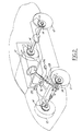
- FIG. 1 illustrates the various parameters with which a system according to this invention operates.
- Turn angle, ⁇ 1 is a measure of the steering angle at which the left front steered road wheel is positioned. This is a function of the steering wheel position as input by a vehicle operator.
- Longitudinal velocity, U is a measure of the forward velocity of the vehicle.
- Lateral velocity, V is a measure of the lateral velocity of the vehicle.
- Yaw rate, r is a measure of the rate of rotation of the vehicle about a vertical axis.
- Slip angle, ⁇ 1 is a measure of the angle between the steered angle of the road wheel and the direction of travel of the road wheel, d rw .
- Normal force is the force usually associated with the vehicle's static weight, which acts downwardly through the road wheel and tire; however, it may be defined to include dynamic changes due to pitch and roll.
- tire lateral force, F tire is a measure of the lateral tire force developed at the interface of the tire with the road.
- a vehicle equipped with a system for dynamically determining an operating state of a motor vehicle includes a plurality of road wheels, 12, in this case four in number.
- a control module, 16 receives signals from various sensors within the vehicle and operates various devices such as brake actuators 15.
- the principal sensors from which control module 16 receives information are speed sensors 14 through speed module 22, steering angle sensor 24, yaw rate sensor 26 and lateral acceleration sensor 28.
- one type suitable for use with a system according to the present invention comprises a speed module 22 for receiving input from speed sensors 14 located at each of the four wheels.
- the speed module derives a longitudinal vehicle speed signal by combining the signals from the speed sensors 14.
- One such type of speed signal module 22 is embodied in ABS brake control modules presently used in Ford Motor Company vehicles.
- the individual wheel speeds are ascertained using pulse generators disposed at each wheel in a conventional manner.
- FIGS. 2, 3 and 4 An example of a steering angle sensor suitable for use according to the present invention is shown in FIGS. 2, 3 and 4. Usage of the illustrated turn angle sensor is explained in U.S. Pat. No. 4,621,833, which is assigned to the assignee of the present invention, and which is hereby incorporated by reference.
- the sensor illustrated in FIGS. 3 and 4 co-operates with control module 16 to produce a first signal representing the turn angle, ⁇ sw , corresponding to the angle a steering wheel 32 is turned by the operator. From the steering angle ⁇ sw , the actual steered angles ⁇ 1 and ⁇ 2 for the left and right front steerable road wheels can be mathematically determined in accordance with a mechanical steering ratio for the vehicle.
- Steering angle sensor 24 includes means for measuring ⁇ sw from a centre position determined by the steering angle sensor in conjunction with control module 16.
- turn angle sensor 24 comprises shutter wheel 90, attached to steering shaft 30, which rotates in unison with the steering wheel as the steering wheel is turned by the operator of the vehicle.
- Shutter wheel 90 has a plurality of apertures 92, in this case 20 in number, which apertures serve to trigger the activity of detectors A and B as the shutter wheel is rotated with the steering system of the vehicle. Because there are 20 apertures contained within shutter wheel 90, the steering angle sensor provides a signal 80 times during one revolution of the steering wheel and as a result each of the 80 signals or steps indicates 4.5 degrees of rotation of the steering system. It should be recognised that higher resolution may be obtained by increasing the number of apertures.
- control module 16 The outputs of detectors A and B are fed into control module 16 and in this manner the control module is allowed to track the rotation by counting the number of 4.5 degree steps the system has rotated from a predetermined centre position.
- the illustrated steering angle sensor is exemplary of a class of devices which may be used for the purpose of determining the steering angle and for providing a signal representative of the steering angle to the control module.
- a rotary slide wire potentiometer or other known devices, for this purpose.
- a yaw rate sensor detects the rotational rate of the motor vehicle about a vertical axis and outputs a signal that is proportional to the vehicle rate of yaw in radians per second.
- One problem associated with some yaw rate sensors is electronic drift. This is a condition which, if not accounted for, would result in considerable accumulated error in the indicated yaw rate.
- An additional problem associated with the use of less expensive yaw rate sensors is referred to as DC offset. This condition causes a relatively constant error component in the output of the yaw rate sensor.
- a yaw rate sensor such as that available from Systron Donner/Inertial, 2700 Systron Drive, Concord, CA 94518, and specifically model AQRS-00075-204 has been determined to work advantageously in the present invention; however, drift and DC offset must be compensated for to provide maximum accuracy.
- Lateral acceleration sensors provide a signal that is proportional to the lateral acceleration of the motor vehicle.
- relatively low cost lateral acceleration sensors also suffer from drift and DC offset.
- a lateral acceleration sensor such as that available from Texas Instruments, 34 Forest Street, Attleboro, MA 02703, and specifically model EX3426-260 has been determined to work advantageously in the present invention.
- the problems of drift and DC offset must be accounted for to provide maximum accuracy.
- a processor means within control module 16 operates on data provided by speed module 22, steering angle sensor 24, yaw rate sensor 26 and lateral acceleration sensor 28. Data from the speed module, steering angle, yaw rate and lateral acceleration sensors are fed into a central processor unit (CPU) 56, by means of input/output circuits (I/O), 54.
- CPU central processor unit
- I/O input/output circuits
- the central processor and its associated peripheral equipment could be structured according to several known architectures.
- the processor is configured so that a control program is sequentially read for each-unit command from a read-only memory (ROM), 60, which stores preset control programs. Unit commands are executed by the central processor.
- the I/O device serves to connect the balance of the microprocessor with the other components of the system, such as the sensors and control devices.
- a random access memory (RAM), 58 stores data for use by the CPU.
- RAM random access memory
- a number of different microprocessors could be used to practice the present invention such as the Model 8096 made by the Intel Corporation, or other microprocessors known in the art.
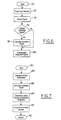
- the CPU processes data from the speed module, steering angle, yaw rate and lateral acceleration sensors according to the algorithms shown in FIGS. 6 and 7 to compensate yaw rate and lateral acceleration signals and to determine therefrom a lateral velocity signal for controlling the dynamics of the motor vehicle.
- control module 16 gives the order to read the output from the various sensors, which in the preferred embodiment provides the individual wheel and vehicle longitudinal speeds (L ws , R ws , U) from the speed module 22, steering angle ( ⁇ sw ), yaw rate (r meas ) and lateral acceleration (A lat meas ).
- a state predictor estimates a value expected for the measured operating state and generates a second signal corresponding to a predicted yaw rate, r pred .
- the control module makes a determination as to whether the motor vehicle is operating in a predetermined state for which reliable predictions may be made. With respect to predicting the yaw rate, it has been determined that the yaw rate prediction based on wheel speed difference is reliable for all times except when the ABS system is engaged to limit wheel slippage. When the ABS system is so engaged, an ABS event flag is set to "true", indicating that the predicted yaw rate should not be used. In this event, the control module advances to block 80. However, if the ABS event flag is "false", the control module advances to block 78 where a third signal is generated representing an erroneous component of the measured yaw rate signal. This signal may also be referred to as the yaw correction signal.
- a compensated lateral acceleration signal can be determined through the implementation of a similar algorithm.
- the first difference occurs at block 74 where the state predictor estimates a value expected for the measured operating state, and generates the second signal which in this case is the predicted lateral acceleration, A lat pred .
- the yaw rate is predicted according to the following relationship:
- the control module should predict lateral acceleration after determining the compensated yaw rate, r comp , to obtain improved accuracy in A lat pred .
- the control module makes a determination as to whether the motor vehicle is operating in a predetermined state for which reliable predictions may be made. With respect to predicting the lateral acceleration, it has been determined that the lateral acceleration predictions based on r comp should only be used when r comp is less than approximately 0.5 radians per second. In the event r comp is greater than 0.5 radians per second, the control module jumps ahead to block 80. However, if the r comp is less than 0.5 radians per second the control module advances to block 78 where a third signal is generated representing an erroneous component of the measured yaw rate signal. This signal may also be referred to as the lateral acceleration correction signal.
- the lateral acceleration correction signal is generated according to the following relationship: where W(s) is a transfer function having the form 1 ⁇ s+1 .
- the algorithm starts at start block 82, which could be entered after the yaw rate and lateral acceleration signals have been compensated.
- the control module proceeds to block 84 and calculates a variety of vehicle operating parameters necessary to sufficiently describe the operating state of the vehicle at the given instant in time for which the data was acquired.
- One such operating parameter includes the lateral force existing at each tire.
- the tire lateral force, F tire 1-4 can be determined according to the following relationship: where K tire represents a tire property giving lateral force for a given slip angle and normal force, ⁇ 1-4 represents the slip angle at each of the four respective tires and Fn 1-4 represents the normal force at each of the four respective tires.
- the normal force Fn 1-4 is initialised as a static design load, and in the preferred embodiment is dynamically updated in accordance with conventional vehicle dynamics equations derived for the specific suspension geometry to account for pitch and roll induced weight transfer. Additionally, it is contemplated that some type of load sensing apparatus could be used to directly determine the normal force at each of the four tires.
- the control module then advances to block 86.
- the control module generates an observer corrector signal that is proportional to the difference in the measured lateral acceleration signal, A lat meas , and a signal representing an estimate of the lateral tire forces, A tf .
- This corrector signal is generated according to the following relationship: where k obs represents an empirically determined observer gain developed in accordance with asymptotic observer theory.
- the control module advances to block 88, where the corrector signal is used to determine the estimate of the lateral velocity, V.
- the control module advances to block 90 where the lateral velocity can be used for controlling various dynamics of the motor vehicle through the controlled devices.
- the controlled devices 12 will thereafter be given commands by I/O device 54.
- the control module After giving a control command at block 90, the control module will return to start block 82 via return block 92 running the algorithms represented by FIGS. 6 and 7.
- the steering angle sensor will measure the angle of the steering wheel and the control module will determine the steered angles of the front wheels.
- the individual wheels speeds will be ascertained from an existing ABS module, from which the vehicle longitudinal speed can also be determined.
- the yaw rate sensor and lateral acceleration sensor will measure their respective data. This data represents the operating state of the motor vehicle for the instant in time at which the data was sampled.
- the control module will next go about determining the remaining data necessary to properly control the dynamics of the vehicle by controlling the various controlled devices with which the vehicle may be equipped.
- control module proceeds to compensate the measured yaw rate signal first, as it will be used in the determination of several variables to be used in the ultimate determination of the lateral velocity of the vehicle at that instant. As such, the control module proceeds to determine a prediction of the yaw rate. With this value, the control module next determines a yaw rate correction signal. The yaw rate correction signal is then used to determine the compensated yaw rate, which at this point is a very accurate representation of the actual vehicle yaw rate.
- control module would have simply used the yaw rate correction signal determined prior to ABS engagement.
- the control module then proceeds to determine the compensated lateral acceleration signal, using the compensated yaw rate signal. Much like the determination of the compensated yaw rate signal, the control module first predicts a lateral acceleration signal and generates a lateral acceleration correction signal therefrom. This lateral acceleration signal is then used to compensate the measured lateral acceleration signal, assuming that the compensated yaw rate is below a predetermined minimum. Presently, the best accuracy has been obtained using a value of 0.5 radians per second.
- the control module can then use this data to determine the remaining vehicle parameters necessary for the determination of the lateral velocity.
- the control module determines the lateral tire forces by determining the normal forces and the slip angles for each tire.
- the normal forces can be as simple as the static loading from ROM, or they can be estimated taking into account weight transfer due to pitch and roll. In the event of a suspension having force measuring means, the normal force may be read directly therefrom.
- the normal force and calculated slip angles for each tire can be used to provide an estimate of the lateral force being generated at the road/tire interface.
- the control module then numerically integrates the data to determine the lateral velocity of the vehicle for that instant in time.
- the resulting signal is used, in combination with the other signals to more accurately control the dynamics of the vehicle through the various controlled devices.
- the combination of yaw rate, lateral acceleration and lateral velocity would allow the ABS brake system to enhance vehicle stability during a turn.
- the control module could ascertain that the yaw rate, lateral acceleration and lateral velocity are not consistent with a drivers steering input, thereby requiring independent brake modulation to impart the appropriate yaw, lateral acceleration and lateral velocity for the given operator command.
- the control module may determine that throttle intervention would further enhance the stability of the motor vehicle.
- the control module may also adjust roll stiffness, and other suspension parameters to transfer weight to wheels which could enhance stability.
Landscapes
- Engineering & Computer Science (AREA)
- Mechanical Engineering (AREA)
- Automation & Control Theory (AREA)
- Transportation (AREA)
- Steering Control In Accordance With Driving Conditions (AREA)
- Regulating Braking Force (AREA)
- Vehicle Body Suspensions (AREA)
Applications Claiming Priority (2)
| Application Number | Priority Date | Filing Date | Title |
|---|---|---|---|
| US08/638,628 US5809434A (en) | 1996-04-26 | 1996-04-26 | Method and apparatus for dynamically determically determining an operating state of a motor vehicle |
| US638628 | 1996-04-26 |
Publications (2)
| Publication Number | Publication Date |
|---|---|
| EP0803386A1 true EP0803386A1 (fr) | 1997-10-29 |
| EP0803386B1 EP0803386B1 (fr) | 2001-08-22 |
Family
ID=24560805
Family Applications (1)
| Application Number | Title | Priority Date | Filing Date |
|---|---|---|---|
| EP97302282A Expired - Lifetime EP0803386B1 (fr) | 1996-04-26 | 1997-04-03 | Système et méthode pour la détermination dynamique de l'état opérationnel d'un véhicule automobile |
Country Status (4)
| Country | Link |
|---|---|
| US (1) | US5809434A (fr) |
| EP (1) | EP0803386B1 (fr) |
| CA (1) | CA2203326A1 (fr) |
| DE (1) | DE69706222T2 (fr) |
Cited By (3)
| Publication number | Priority date | Publication date | Assignee | Title |
|---|---|---|---|---|
| US6526342B1 (en) | 1998-10-16 | 2003-02-25 | Land Rover | Vehicle suspensions |
| EP1815350A2 (fr) * | 2004-09-20 | 2007-08-08 | Darrell Voss | Systemes ameliores pour vehicule et procede associe |
| CN107357296A (zh) * | 2017-08-18 | 2017-11-17 | 西安鸣士机电开发有限公司 | 一种育秧机自动纠偏系统、方法及育秧机 |
Families Citing this family (66)
| Publication number | Priority date | Publication date | Assignee | Title |
|---|---|---|---|---|
| EP0991543B1 (fr) * | 1997-07-01 | 2004-06-09 | Dynamotive, L.L.C. | Systeme de freinage anti-tonneau |
| US6560518B1 (en) * | 1998-11-06 | 2003-05-06 | Ford Motor Company | Algorithm for computing vehicle's steering ratio under dynamic maneuver |
| US6314329B1 (en) | 1998-11-06 | 2001-11-06 | Visteon Global Technologies, Inc. | Compensation algorithm for initializing yaw rate sensor's zero point offset |
| US6161905A (en) * | 1998-11-19 | 2000-12-19 | General Motors Corporation | Active brake control including estimation of yaw rate and slip angle |
| US6185485B1 (en) * | 1998-12-22 | 2001-02-06 | Ford Global Technologies, Inc | Relative vehicle platform having synchronized adaptive offset calibration for lateral accelerometer and steering angle sensor |
| JP3649036B2 (ja) * | 1999-03-26 | 2005-05-18 | 日産自動車株式会社 | ヨーレート推定装置 |
| US6332104B1 (en) | 1999-12-21 | 2001-12-18 | Ford Global Technologies, Inc. | Roll over detection for an automotive vehicle |
| US6324446B1 (en) | 1999-12-21 | 2001-11-27 | Ford Global Technologies, Inc. | Roll over stability control for an automotive vehicle |
| US6263261B1 (en) | 1999-12-21 | 2001-07-17 | Ford Global Technologies, Inc. | Roll over stability control for an automotive vehicle |
| US6834218B2 (en) | 2001-11-05 | 2004-12-21 | Ford Global Technologies, Llc | Roll over stability control for an automotive vehicle |
| US6353777B1 (en) | 2000-08-16 | 2002-03-05 | Ford Global Technologies, Inc. | Path correction for lane change analysis |
| US6356188B1 (en) | 2000-09-25 | 2002-03-12 | Ford Global Technologies, Inc. | Wheel lift identification for an automotive vehicle |
| US6904350B2 (en) | 2000-09-25 | 2005-06-07 | Ford Global Technologies, Llc | System for dynamically determining the wheel grounding and wheel lifting conditions and their applications in roll stability control |
| US7233236B2 (en) | 2000-09-25 | 2007-06-19 | Ford Global Technologies, Llc | Passive wheel lift identification for an automotive vehicle using operating input torque to wheel |
| US7132937B2 (en) | 2000-09-25 | 2006-11-07 | Ford Global Technologies, Llc | Wheel lift identification for an automotive vehicle using passive and active detection |
| US7109856B2 (en) | 2000-09-25 | 2006-09-19 | Ford Global Technologies, Llc | Wheel lifted and grounded identification for an automotive vehicle |
| US6397127B1 (en) | 2000-09-25 | 2002-05-28 | Ford Global Technologies, Inc. | Steering actuated wheel lift identification for an automotive vehicle |
| JP4187918B2 (ja) * | 2000-10-11 | 2008-11-26 | 富士重工業株式会社 | 車両挙動制御装置 |
| US6799092B2 (en) | 2001-02-21 | 2004-09-28 | Ford Global Technologies, Llc | Rollover stability control for an automotive vehicle using rear wheel steering and brake control |
| US6631317B2 (en) | 2001-10-01 | 2003-10-07 | Ford Global Technologies, Inc. | Attitude sensing system for an automotive vehicle |
| US6654674B2 (en) | 2001-11-21 | 2003-11-25 | Ford Global Technologies, Llc | Enhanced system for yaw stability control system to include roll stability control function |
| US6761243B2 (en) | 2001-12-31 | 2004-07-13 | Visteon Global Technologies, Inc. | Steering control with variable damper assistance and method implementing the same |
| US6618651B1 (en) | 2002-02-25 | 2003-09-09 | Visteon Global Technologies, Inc. | Estimating vehicle velocities using linear-parameter-varying and gain varying scheduling theories |
| US6556908B1 (en) | 2002-03-04 | 2003-04-29 | Ford Global Technologies, Inc. | Attitude sensing system for an automotive vehicle relative to the road |
| US6718248B2 (en) | 2002-06-19 | 2004-04-06 | Ford Global Technologies, Llc | System for detecting surface profile of a driving road |
| US6684140B2 (en) | 2002-06-19 | 2004-01-27 | Ford Global Technologies, Llc | System for sensing vehicle global and relative attitudes using suspension height sensors |
| US7079928B2 (en) | 2002-08-01 | 2006-07-18 | Ford Global Technologies, Llc | System and method for determining a wheel departure angle for a rollover control system with respect to road roll rate and loading misalignment |
| US7194351B2 (en) | 2002-08-01 | 2007-03-20 | Ford Global Technologies, Llc | System and method for determining a wheel departure angle for a rollover control system |
| US7085639B2 (en) | 2002-08-01 | 2006-08-01 | Ford Global Technologies, Llc | System and method for characterizing the road bank for vehicle roll stability control |
| US6941205B2 (en) | 2002-08-01 | 2005-09-06 | Ford Global Technologies, Llc. | System and method for deteching roll rate sensor fault |
| US7302331B2 (en) | 2002-08-01 | 2007-11-27 | Ford Global Technologies, Inc. | Wheel lift identification for an automotive vehicle |
| US7003389B2 (en) | 2002-08-01 | 2006-02-21 | Ford Global Technologies, Llc | System and method for characterizing vehicle body to road angle for vehicle roll stability control |
| US6963797B2 (en) | 2002-08-05 | 2005-11-08 | Ford Global Technologies, Llc | System and method for determining an amount of control for operating a rollover control system |
| US7430468B2 (en) | 2002-08-05 | 2008-09-30 | Ford Global Technologies, Llc | System and method for sensitizing the activation criteria of a rollover control system |
| US6961648B2 (en) | 2002-08-05 | 2005-11-01 | Ford Motor Company | System and method for desensitizing the activation criteria of a rollover control system |
| US7085642B2 (en) | 2002-08-05 | 2006-08-01 | Ford Global Technologies, Llc | Method and system for correcting sensor offsets |
| US6738699B2 (en) | 2002-08-26 | 2004-05-18 | Visteon Global Technologies, Inc. | Vehicle steering system control based on a model-matching strategy |
| JP4127062B2 (ja) * | 2003-01-22 | 2008-07-30 | トヨタ自動車株式会社 | 横加速度センサのドリフト量推定装置、横加速度センサの出力補正装置及び路面摩擦状態推定装置 |
| US20040153216A1 (en) * | 2003-01-30 | 2004-08-05 | Visteon Global Technologies, Inc. | Method for estimating a vehicle's velocity |
| US7653471B2 (en) | 2003-02-26 | 2010-01-26 | Ford Global Technologies, Llc | Active driven wheel lift identification for an automotive vehicle |
| US9162656B2 (en) | 2003-02-26 | 2015-10-20 | Ford Global Technologies, Llc | Active driven wheel lift identification for an automotive vehicle |
| US7136731B2 (en) | 2003-06-11 | 2006-11-14 | Ford Global Technologies, Llc | System for determining vehicular relative roll angle during a potential rollover event |
| EP1680290A4 (fr) * | 2003-10-17 | 2007-11-07 | Active Air Suspension Ltd | Commande de suspension de vehicule |
| US7031816B2 (en) * | 2004-03-23 | 2006-04-18 | Continental Teves, Inc. | Active rollover protection |
| US7831354B2 (en) * | 2004-03-23 | 2010-11-09 | Continental Teves, Inc. | Body state estimation of a vehicle |
| US7369927B2 (en) | 2004-04-02 | 2008-05-06 | Continental Teves, Inc. | Active rollover protection utilizing steering angle rate map |
| US7308350B2 (en) | 2004-05-20 | 2007-12-11 | Ford Global Technologies, Llc | Method and apparatus for determining adaptive brake gain parameters for use in a safety system of an automotive vehicle |
| US6901319B1 (en) * | 2004-07-06 | 2005-05-31 | Deere & Company | System and method for controlling a ground vehicle |
| US7640081B2 (en) | 2004-10-01 | 2009-12-29 | Ford Global Technologies, Llc | Roll stability control using four-wheel drive |
| US7715965B2 (en) | 2004-10-15 | 2010-05-11 | Ford Global Technologies | System and method for qualitatively determining vehicle loading conditions |
| US7668645B2 (en) | 2004-10-15 | 2010-02-23 | Ford Global Technologies | System and method for dynamically determining vehicle loading and vertical loading distance for use in a vehicle dynamic control system |
| US7239952B2 (en) * | 2004-12-08 | 2007-07-03 | Continental Teves, Inc. | Reduced order parameter identification for vehicle rollover control system |
| US7660654B2 (en) | 2004-12-13 | 2010-02-09 | Ford Global Technologies, Llc | System for dynamically determining vehicle rear/trunk loading for use in a vehicle control system |
| US7557697B2 (en) * | 2005-02-22 | 2009-07-07 | Continental Teves, Inc. | System to measure wheel liftoff |
| US7686404B2 (en) * | 2005-02-23 | 2010-03-30 | Continental Teves, Inc. | Electro-hydraulic braking system |
| US8165749B2 (en) * | 2005-03-31 | 2012-04-24 | Honda Motor Co., Ltd | Control system for adjustable damping force damper |
| US7590481B2 (en) | 2005-09-19 | 2009-09-15 | Ford Global Technologies, Llc | Integrated vehicle control system using dynamically determined vehicle conditions |
| US7600826B2 (en) | 2005-11-09 | 2009-10-13 | Ford Global Technologies, Llc | System for dynamically determining axle loadings of a moving vehicle using integrated sensing system and its application in vehicle dynamics controls |
| US8121758B2 (en) | 2005-11-09 | 2012-02-21 | Ford Global Technologies | System for determining torque and tire forces using integrated sensing system |
| US8392882B2 (en) * | 2006-11-30 | 2013-03-05 | Caterpillar Inc. | Engine state-based control of software functions |
| US8195357B2 (en) * | 2008-04-16 | 2012-06-05 | GM Global Technology Operations LLC | In-vehicle sensor-based calibration algorithm for yaw rate sensor calibration |
| US9157737B2 (en) * | 2008-06-11 | 2015-10-13 | Trimble Navigation Limited | Altimeter with calibration |
| US8566034B1 (en) | 2008-06-11 | 2013-10-22 | Trimble Navigation Limited | Inclinometer with calibration |
| US8150651B2 (en) * | 2008-06-11 | 2012-04-03 | Trimble Navigation Limited | Acceleration compensated inclinometer |
| US20100131141A1 (en) * | 2008-11-21 | 2010-05-27 | Gm Global Technology Operations, Inc. | Bank angle estimation via vehicle lateral velocity with force tables |
| US9371073B1 (en) | 2015-06-19 | 2016-06-21 | GM Global Technology Operations LLC | Real-time determination of tire normal forces |
Citations (15)
| Publication number | Priority date | Publication date | Assignee | Title |
|---|---|---|---|---|
| US4470124A (en) * | 1981-06-01 | 1984-09-04 | Honda Giken Kogyo Kabushiki Kaisha | Method of adjusting the zero-point of rate type sensor |
| US4927170A (en) * | 1988-03-08 | 1990-05-22 | Mitsubishi Denki Kabushiki Kaisha | Suspension control apparatus for an automotive vehicle |
| JPH02151569A (ja) * | 1988-11-30 | 1990-06-11 | Nissan Motor Co Ltd | 車両運動推定装置 |
| JPH02262416A (ja) * | 1989-03-31 | 1990-10-25 | Aisin Seiki Co Ltd | 車両用サスペンション制御装置 |
| DE4123234C1 (fr) * | 1991-07-13 | 1992-08-27 | Mercedes-Benz Aktiengesellschaft, 7000 Stuttgart, De | |
| JPH05616A (ja) * | 1990-08-10 | 1993-01-08 | Matsushita Electric Ind Co Ltd | サスペンシヨン制御装置と四輪操舵装置 |
| JPH05193322A (ja) * | 1992-01-14 | 1993-08-03 | Nippondenso Co Ltd | 車両のサスペンション制御装置 |
| DE4228893A1 (de) * | 1992-08-29 | 1994-03-03 | Bosch Gmbh Robert | System zur Beeinflussung der Fahrdynamik eines Kraftfahrzeugs |
| US5321616A (en) * | 1990-08-10 | 1994-06-14 | Matsushita Electric Industrial Co., Ltd. | Vehicle control apparatus |
| JPH06230123A (ja) * | 1993-01-29 | 1994-08-19 | Aisin Seiki Co Ltd | 車載用超音波計測装置 |
| JPH06288876A (ja) * | 1993-03-30 | 1994-10-18 | Toyota Motor Corp | 車両走行状態検出装置 |
| DE4340719A1 (de) * | 1993-11-30 | 1995-06-01 | Siemens Ag | Schaltungsanordnung zum Auswerten der Signale eines Giergeschwindigkeitssensors |
| EP0663333A1 (fr) * | 1994-01-14 | 1995-07-19 | Matsushita Electric Industrial Co., Ltd. | Dispositif de commande d'angle de direction |
| DE19502858C1 (de) * | 1995-01-30 | 1996-07-11 | Siemens Ag | Verfahren und Schaltungsanordnung zum Kompensieren der Signalfehler eines Giergeschwindigkeitssensors |
| JPH08216644A (ja) * | 1995-02-15 | 1996-08-27 | Unisia Jecs Corp | サスペンション制御信号作成方法 |
Family Cites Families (10)
| Publication number | Priority date | Publication date | Assignee | Title |
|---|---|---|---|---|
| JPH06104455B2 (ja) * | 1985-03-15 | 1994-12-21 | 日産自動車株式会社 | 車両運動状態推定装置 |
| US4882693A (en) * | 1987-12-28 | 1989-11-21 | Ford Motor Company | Automotive system for dynamically determining road adhesion |
| GB8909074D0 (en) * | 1989-04-21 | 1989-06-07 | Lotus Group Plc | Vehicle control system |
| US5123497A (en) * | 1990-12-20 | 1992-06-23 | Ford Motor Company | Automotive apparatus and method for dynamically determining centripetal force of a vehicle |
| DE4121954A1 (de) * | 1991-07-03 | 1993-01-07 | Bosch Gmbh Robert | Verfahren zur gewinnung der giergeschwindigkeit und/oder quergeschwindigkeit |
| GB9216547D0 (en) * | 1992-08-04 | 1992-09-16 | Lotus Car | A wheeled vehicle steering system |
| US5608631A (en) * | 1993-03-16 | 1997-03-04 | Mitsubishi Denki Kabushiki Kaisha | Apparatus and method for detecting acceleration of motor vehicle with high accuracy and anti-skid control apparatus using the same |
| JP3060923B2 (ja) * | 1995-11-24 | 2000-07-10 | トヨタ自動車株式会社 | 車両状態推定装置 |
| US5899952A (en) * | 1995-12-27 | 1999-05-04 | Toyota Jidosha Kabushiki Kaisha | Device for estimating slip angle of vehicle body through interrelation thereof with yaw rate |
| DE19615311B4 (de) * | 1996-04-18 | 2006-06-29 | Robert Bosch Gmbh | Verfahren und Vorrichtung zur Regelung einer die Fahrzeugbewegung repräsentierenden Bewegungsgröße |
-
1996
- 1996-04-26 US US08/638,628 patent/US5809434A/en not_active Expired - Fee Related
-
1997
- 1997-04-03 DE DE69706222T patent/DE69706222T2/de not_active Expired - Fee Related
- 1997-04-03 EP EP97302282A patent/EP0803386B1/fr not_active Expired - Lifetime
- 1997-04-22 CA CA002203326A patent/CA2203326A1/fr not_active Abandoned
Patent Citations (15)
| Publication number | Priority date | Publication date | Assignee | Title |
|---|---|---|---|---|
| US4470124A (en) * | 1981-06-01 | 1984-09-04 | Honda Giken Kogyo Kabushiki Kaisha | Method of adjusting the zero-point of rate type sensor |
| US4927170A (en) * | 1988-03-08 | 1990-05-22 | Mitsubishi Denki Kabushiki Kaisha | Suspension control apparatus for an automotive vehicle |
| JPH02151569A (ja) * | 1988-11-30 | 1990-06-11 | Nissan Motor Co Ltd | 車両運動推定装置 |
| JPH02262416A (ja) * | 1989-03-31 | 1990-10-25 | Aisin Seiki Co Ltd | 車両用サスペンション制御装置 |
| US5321616A (en) * | 1990-08-10 | 1994-06-14 | Matsushita Electric Industrial Co., Ltd. | Vehicle control apparatus |
| JPH05616A (ja) * | 1990-08-10 | 1993-01-08 | Matsushita Electric Ind Co Ltd | サスペンシヨン制御装置と四輪操舵装置 |
| DE4123234C1 (fr) * | 1991-07-13 | 1992-08-27 | Mercedes-Benz Aktiengesellschaft, 7000 Stuttgart, De | |
| JPH05193322A (ja) * | 1992-01-14 | 1993-08-03 | Nippondenso Co Ltd | 車両のサスペンション制御装置 |
| DE4228893A1 (de) * | 1992-08-29 | 1994-03-03 | Bosch Gmbh Robert | System zur Beeinflussung der Fahrdynamik eines Kraftfahrzeugs |
| JPH06230123A (ja) * | 1993-01-29 | 1994-08-19 | Aisin Seiki Co Ltd | 車載用超音波計測装置 |
| JPH06288876A (ja) * | 1993-03-30 | 1994-10-18 | Toyota Motor Corp | 車両走行状態検出装置 |
| DE4340719A1 (de) * | 1993-11-30 | 1995-06-01 | Siemens Ag | Schaltungsanordnung zum Auswerten der Signale eines Giergeschwindigkeitssensors |
| EP0663333A1 (fr) * | 1994-01-14 | 1995-07-19 | Matsushita Electric Industrial Co., Ltd. | Dispositif de commande d'angle de direction |
| DE19502858C1 (de) * | 1995-01-30 | 1996-07-11 | Siemens Ag | Verfahren und Schaltungsanordnung zum Kompensieren der Signalfehler eines Giergeschwindigkeitssensors |
| JPH08216644A (ja) * | 1995-02-15 | 1996-08-27 | Unisia Jecs Corp | サスペンション制御信号作成方法 |
Non-Patent Citations (7)
| Title |
|---|
| PATENT ABSTRACTS OF JAPAN vol. 014, no. 399 (M - 1017) 29 August 1990 (1990-08-29) * |
| PATENT ABSTRACTS OF JAPAN vol. 015, no. 010 (M - 1068) 10 January 1991 (1991-01-10) * |
| PATENT ABSTRACTS OF JAPAN vol. 017, no. 260 (M - 1414) 21 May 1993 (1993-05-21) * |
| PATENT ABSTRACTS OF JAPAN vol. 017, no. 623 (M - 1511) 17 November 1993 (1993-11-17) * |
| PATENT ABSTRACTS OF JAPAN vol. 018, no. 609 (P - 1828) 18 November 1994 (1994-11-18) * |
| PATENT ABSTRACTS OF JAPAN vol. 095, no. 001 28 February 1995 (1995-02-28) * |
| PATENT ABSTRACTS OF JAPAN vol. 096, no. 012 26 December 1996 (1996-12-26) * |
Cited By (5)
| Publication number | Priority date | Publication date | Assignee | Title |
|---|---|---|---|---|
| US6526342B1 (en) | 1998-10-16 | 2003-02-25 | Land Rover | Vehicle suspensions |
| EP1815350A2 (fr) * | 2004-09-20 | 2007-08-08 | Darrell Voss | Systemes ameliores pour vehicule et procede associe |
| EP1815350A4 (fr) * | 2004-09-20 | 2010-03-10 | Darrell Voss | Systemes ameliores pour vehicule et procede associe |
| CN107357296A (zh) * | 2017-08-18 | 2017-11-17 | 西安鸣士机电开发有限公司 | 一种育秧机自动纠偏系统、方法及育秧机 |
| CN107357296B (zh) * | 2017-08-18 | 2021-02-02 | 西安鸣士机电开发有限公司 | 一种育秧机自动纠偏系统、方法及育秧机 |
Also Published As
| Publication number | Publication date |
|---|---|
| EP0803386B1 (fr) | 2001-08-22 |
| DE69706222D1 (de) | 2001-09-27 |
| DE69706222T2 (de) | 2001-12-06 |
| CA2203326A1 (fr) | 1997-10-26 |
| US5809434A (en) | 1998-09-15 |
Similar Documents
| Publication | Publication Date | Title |
|---|---|---|
| US5742918A (en) | Method and apparatus for dynamically compensating a lateral acceleration of a motor vehicle | |
| US5809434A (en) | Method and apparatus for dynamically determically determining an operating state of a motor vehicle | |
| US5742919A (en) | Method and apparatus for dynamically determining a lateral velocity of a motor vehicle | |
| US6804584B2 (en) | Method for determining the roll angle of a vehicle using an estimation of road bank angle | |
| US6351694B1 (en) | Method for robust estimation of road bank angle | |
| EP0983919B1 (fr) | Procédé pour déterminer l'angle d'inclinaison d'un véhicule roulant | |
| US7222007B2 (en) | Attitude sensing system for an automotive vehicle relative to the road | |
| US6714851B2 (en) | Method for road grade/vehicle pitch estimation | |
| US6725140B2 (en) | Method and apparatus for determining lateral velocity of a motor vehicle in closed form for all road and driving conditions | |
| US8775048B2 (en) | Method and apparatus for determining a reference vehicle velocity and a rear wheel speed in a vehicle having three speed sensors | |
| US7184868B2 (en) | Vehicle dynamics behavior reproduction system | |
| US6904349B2 (en) | Method of estimating quantities that represent state of vehicle | |
| EP1013525B1 (fr) | Méthode et appareil pour déterminer la stabilité dynamique d'un véhicule automobile | |
| US7092808B2 (en) | Integrated sensing system for an automotive system | |
| US5446658A (en) | Method and apparatus for estimating incline and bank angles of a road surface | |
| US6862512B2 (en) | Method and system for controlling the performance of a motor vehicle | |
| US6745112B2 (en) | Method of estimating quantities that represent state of vehicle | |
| EP1386808B1 (fr) | Système et procédé caractérisant l'angle entre la carrosserie de véhicule et la route pour contrôle de roulis de véhicule | |
| JPH11304663A (ja) | 車両の重心高さの推定演算装置 | |
| KR19990071465A (ko) | 차량운동을나타내는운동량을조정하기위한방법및장치 | |
| KR19990082250A (ko) | 차량의 주행 거동을 표시하는 양을 결정하는방법 | |
| US5040115A (en) | System for monitoring vehicle slip angle | |
| US6915193B2 (en) | Method for determining a longitudinal vehicle velocity by compensating individual wheel speeds using pitch attitude | |
| US6304807B1 (en) | Method for determining the yaw velocity of a vehicle | |
| US20130261875A1 (en) | Control Module for a Vehicle System, the Vehicle System and a Vehicle Having this Vehicle System |
Legal Events
| Date | Code | Title | Description |
|---|---|---|---|
| PUAI | Public reference made under article 153(3) epc to a published international application that has entered the european phase |
Free format text: ORIGINAL CODE: 0009012 |
|
| AK | Designated contracting states |
Kind code of ref document: A1 Designated state(s): DE FR GB |
|
| 17P | Request for examination filed |
Effective date: 19980103 |
|
| 17Q | First examination report despatched |
Effective date: 20000215 |
|
| RTI1 | Title (correction) |
Free format text: SYTEEM AND METHOD FOR DYNAMICALLY DETERMINING AN OPERATING STATE OF A MOTOR VEHICLE |
|
| GRAG | Despatch of communication of intention to grant |
Free format text: ORIGINAL CODE: EPIDOS AGRA |
|
| RTI1 | Title (correction) |
Free format text: SYSTEM AND METHOD FOR DYNAMICALLY DETERMINING AN OPERATING STATE OF A MOTOR VEHICLE |
|
| GRAG | Despatch of communication of intention to grant |
Free format text: ORIGINAL CODE: EPIDOS AGRA |
|
| GRAH | Despatch of communication of intention to grant a patent |
Free format text: ORIGINAL CODE: EPIDOS IGRA |
|
| GRAH | Despatch of communication of intention to grant a patent |
Free format text: ORIGINAL CODE: EPIDOS IGRA |
|
| GRAA | (expected) grant |
Free format text: ORIGINAL CODE: 0009210 |
|
| AK | Designated contracting states |
Kind code of ref document: B1 Designated state(s): DE FR GB |
|
| REF | Corresponds to: |
Ref document number: 69706222 Country of ref document: DE Date of ref document: 20010927 |
|
| REG | Reference to a national code |
Ref country code: GB Ref legal event code: IF02 |
|
| ET | Fr: translation filed | ||
| PLBE | No opposition filed within time limit |
Free format text: ORIGINAL CODE: 0009261 |
|
| STAA | Information on the status of an ep patent application or granted ep patent |
Free format text: STATUS: NO OPPOSITION FILED WITHIN TIME LIMIT |
|
| 26N | No opposition filed | ||
| REG | Reference to a national code |
Ref country code: FR Ref legal event code: TP |
|
| REG | Reference to a national code |
Ref country code: FR Ref legal event code: CD Ref country code: FR Ref legal event code: CA |
|
| PGFP | Annual fee paid to national office [announced via postgrant information from national office to epo] |
Ref country code: GB Payment date: 20080317 Year of fee payment: 12 |
|
| PGFP | Annual fee paid to national office [announced via postgrant information from national office to epo] |
Ref country code: DE Payment date: 20080430 Year of fee payment: 12 |
|
| PGFP | Annual fee paid to national office [announced via postgrant information from national office to epo] |
Ref country code: FR Payment date: 20080403 Year of fee payment: 12 |
|
| GBPC | Gb: european patent ceased through non-payment of renewal fee |
Effective date: 20090403 |
|
| REG | Reference to a national code |
Ref country code: FR Ref legal event code: ST Effective date: 20091231 |
|
| PG25 | Lapsed in a contracting state [announced via postgrant information from national office to epo] |
Ref country code: DE Free format text: LAPSE BECAUSE OF NON-PAYMENT OF DUE FEES Effective date: 20091103 |
|
| PG25 | Lapsed in a contracting state [announced via postgrant information from national office to epo] |
Ref country code: GB Free format text: LAPSE BECAUSE OF NON-PAYMENT OF DUE FEES Effective date: 20090403 Ref country code: FR Free format text: LAPSE BECAUSE OF NON-PAYMENT OF DUE FEES Effective date: 20091222 |