EP0803333A2 - Outil pour forer un trou et insèrer un boulon d'ancrage,et boulon d'ancrage apte à être inséré par l'outil dans une maçonnerie poreuse - Google Patents
Outil pour forer un trou et insèrer un boulon d'ancrage,et boulon d'ancrage apte à être inséré par l'outil dans une maçonnerie poreuse Download PDFInfo
- Publication number
- EP0803333A2 EP0803333A2 EP96118579A EP96118579A EP0803333A2 EP 0803333 A2 EP0803333 A2 EP 0803333A2 EP 96118579 A EP96118579 A EP 96118579A EP 96118579 A EP96118579 A EP 96118579A EP 0803333 A2 EP0803333 A2 EP 0803333A2
- Authority
- EP
- European Patent Office
- Prior art keywords
- expansion
- anchor
- tool
- depth
- hole
- Prior art date
- Legal status (The legal status is an assumption and is not a legal conclusion. Google has not performed a legal analysis and makes no representation as to the accuracy of the status listed.)
- Granted
Links
Images

Classifications
-
- B—PERFORMING OPERATIONS; TRANSPORTING
- B25—HAND TOOLS; PORTABLE POWER-DRIVEN TOOLS; MANIPULATORS
- B25D—PERCUSSIVE TOOLS
- B25D17/00—Details of, or accessories for, portable power-driven percussive tools
- B25D17/005—Attachments or adapters placed between tool and hammer
-
- B—PERFORMING OPERATIONS; TRANSPORTING
- B25—HAND TOOLS; PORTABLE POWER-DRIVEN TOOLS; MANIPULATORS
- B25D—PERCUSSIVE TOOLS
- B25D17/00—Details of, or accessories for, portable power-driven percussive tools
- B25D17/02—Percussive tool bits
-
- F—MECHANICAL ENGINEERING; LIGHTING; HEATING; WEAPONS; BLASTING
- F16—ENGINEERING ELEMENTS AND UNITS; GENERAL MEASURES FOR PRODUCING AND MAINTAINING EFFECTIVE FUNCTIONING OF MACHINES OR INSTALLATIONS; THERMAL INSULATION IN GENERAL
- F16B—DEVICES FOR FASTENING OR SECURING CONSTRUCTIONAL ELEMENTS OR MACHINE PARTS TOGETHER, e.g. NAILS, BOLTS, CIRCLIPS, CLAMPS, CLIPS OR WEDGES; JOINTS OR JOINTING
- F16B13/00—Dowels or other devices fastened in walls or the like by inserting them in holes made therein for that purpose
- F16B13/04—Dowels or other devices fastened in walls or the like by inserting them in holes made therein for that purpose with parts gripping in the hole or behind the reverse side of the wall after inserting from the front
- F16B13/08—Dowels or other devices fastened in walls or the like by inserting them in holes made therein for that purpose with parts gripping in the hole or behind the reverse side of the wall after inserting from the front with separate or non-separate gripping parts moved into their final position in relation to the body of the device without further manual operation
- F16B13/0858—Dowels or other devices fastened in walls or the like by inserting them in holes made therein for that purpose with parts gripping in the hole or behind the reverse side of the wall after inserting from the front with separate or non-separate gripping parts moved into their final position in relation to the body of the device without further manual operation with an expansible sleeve or dowel body driven against a tapered or spherical expander plug
Definitions
- the invention relates to a tool for making a hole in porous masonry such as gas concrete and for setting an expansion anchor in the hole, and an expansion anchor that can be set with the tool.
- the invention has for its object to provide a tool of the type mentioned above so that it allows a hole of a defined depth to be easily punched and the expansion anchor to be set at a depth matched to the depth of the hole.
- the tool according to the invention has a mandrel for driving into the porous masonry. Compared to drilling a hole, hammering in a mandrel has the advantage that the masonry in the area of the hole is compacted and thus solidified, thereby giving the expansion anchor to be set better grip. Another advantage is that no drilling dust has to be removed from the hole.
- the tool has, according to the invention, a depth marking which indicates that the intended hole depth has been reached if, for example, it is flush with a surface of the masonry.
- the tool has a receptacle for the expansion anchor to be set.
- the receptacle is designed, for example, for attaching the expansion anchor.
- it fixes the expansion anchor in the axial direction on the tool at a defined distance from a second depth marking, which indicates that the expansion anchor has reached a set depth in the borehole, for example if it is flush with the surface of the masonry.
- the invention has the advantage that it is possible to produce the hole and set the expansion anchor with one tool.
- the invention has the advantage that the hole depth and the setting depth of the expansion anchor are coordinated.
- the expansion anchor driven in deeper than intended, which can lead to excessive expansion of the expansion anchor and, as a result, to crack formation in the expansion anchor. This would reduce the anchoring force.
- the expansion anchor can be destroyed.
- the invention avoids an insufficient setting depth of the expansion anchor, as a result of which the expansion anchor would be spread less than intended and its anchoring force in the masonry would be reduced.
- the first depth marking is designed as a depth stop, for example in the form of a collar on the tool.
- the mandrel of the tool can be hammered into the masonry until the depth stop lies against the surface of the masonry.
- the front end of the mandrel is preferably tapered like a nail. This reduces the driving resistance. Furthermore, the material of the masonry is pushed radially outwards when the mandrel is driven in, that is to say the masonry is compacted in the peripheral region of the hole and thus solidified. Furthermore, the tip guides the mandrel when driving it into the masonry.
- the expansion anchor according to the invention with the features of claim 4 has an anchor body with expansion tongues that protrude from its front end approximately in the longitudinal direction. Furthermore, the expansion anchor has an expansion body, for example in the form of a truncated cone, which protrudes over the expansion tongues before the expansion anchor is driven into the hole in the masonry.
- the expansion body comes into contact with the hole base and is thereby retained.
- the expansion tongues slide on the expansion body and are spread apart. The expansion tongues are driven diagonally outwards into the masonry through a perforated wall and in this way anchor the expansion anchor in a form-fitting manner in the masonry.
- the expansion body To connect the expansion body with the anchor body before driving into the hole in the masonry and to guide the expansion body in the axial direction when driving in the anchor, the expansion body has a shaft which projects between the expansion tongues before driving in. If the expansion body enters the hole between the expansion tongues when it is driven into the hole, the shaft reaches a longitudinally extending recess in the anchor body, which guides the shaft in the axial direction.
- the shaft and the recess need not have a round cross section, the shaft can, for example, also be flat in the form of a plate and the recess can be designed as a slot with a matching cross section.
- the anchor according to the invention has a cross-sectional constriction of its receptacle for the shaft of the expansion body.
- the shaft comes into the cross-sectional constriction and is clamped there when the expansion body comes between the expansion tongues and spreads them apart.
- the expansion body is non-positively fixed in the axial direction between the expansion tongues, which it spreads apart. This ensures the positive anchoring of the expansion anchor according to the invention in the masonry.
- the narrowing of the cross-section has the advantage that it only exerts a clamping force on the expansion body when the expansion body has already been displaced a little between the expansion tongues, as a result of which the force required to drive in the expansion anchor is reduced.
- Another advantage of the narrowing of the cross section is that it also forms a secure clamping connection when the anchor body is expanded when its expansion tongues are spread apart.
- the anchor body is produced as a rolled sheet metal part or as a bent sheet metal part, which has an indentation at several points on the circumference or an indentation produced by rolling to narrow the cross section.
- the expansion tongues are made by slots from a front end. In this way, the anchor body with the expansion tongues can be produced simply and quickly as a stamped and bent part.
- the anchor body of the expansion anchor has an internal thread at its rear end, into which a screw for fastening an object to the masonry is screwed.
- the screw protrudes a defined distance from the anchor body, in particular to the extent that it corresponds to the distance between the second depth marking and the receptacle for the expansion anchor on the tool according to the invention.
- a hole can be made as described above with the tool according to the invention.
- the screw protrudes from the anchor body by the distance from the receptacle for the expansion anchor to the second depth marking on the tool plus the thickness of the object to be fastened.
- the expansion anchor is inserted through a through hole in the object to be fastened and placed on the screw head by hammer blows as described above.
- the screw protruding from the anchor body by a defined amount ensures the intended setting depth of the expansion anchor. Finally, after setting, the screw only needs to be tightened.
- a second possibility is to produce the hole with the tool according to the invention through the object to be fastened to the masonry with the tool according to the invention. This reduces the hole depth in the masonry by the thickness of the object to be fastened. At the same time, the setting depth of the Expansion anchor reduced by the thickness of the object to be fastened if the screw protrudes from the anchor body in accordance with the distance from the receptacle for the expansion anchor from the second depth marking on the tool.
- the screw in the anchor body is preferably secured against unintentional twisting, for example by attaching a grain, using a drop of securing lacquer or the like.
- a deformable sleeve of defined length is placed on the screw between the head of the screw and the anchor body. This sleeve determines how far the screw protrudes from the anchor body. Their length corresponds to the distance of the receptacle for the expansion anchor from the second depth marking on the tool according to the invention or is longer by the thickness of an object to be attached to the masonry.
- the screw is tightened and the sleeve is compressed.
- the sleeve does not interfere with the tightening of the screw, it only defines the exact length by which the screw protrudes from the anchor body.
- sleeves of different lengths for attaching objects of different thicknesses to the masonry are identified by, for example, colored markings or the like, so that it is easy to see which expansion anchor is provided for a specific thickness of an object to be attached.
- the tool according to the invention shown in FIG. 1, generally designated 10, has the shape of a mandrel 12 and is designed for clamping in a quick-action drill chuck, not shown, with grooves 14 at its rear end.
- the mandrel 12 In its central region, the mandrel 12 has a collar 16, which is integral with it, as a depth stop. A front end 18 of the mandrel 12 is pointed like a nail.
- a cylindrical blind hole of defined depth can be produced in a porous masonry, for example in gas concrete, by driving in the mandrel 12, for example with a hammer, until the depth stop 16 comes into contact with a surface of the masonry.
- the tool 10 according to the invention is also suitable for driving into a porous masonry with a hammer drill or hammer drill known per se, using their hammer mechanisms, the rotary movement of the drill or hammer drill not interfering with the driving.
- a receptacle 20 for an expansion anchor 28 shown in FIGS. 2 and 3 is formed at the front end of the mandrel 12.
- the receptacle 20 has an annular step 22 on which the mandrel 12 tapers towards the front and on which it merges into a short cylindrical extension 24 which ends with the tip 18.
- the ring step 22 forms a stop for the expansion anchor 28, which fixes it in the axial direction on the mandrel 12 when it is placed in a hole made with the mandrel 12.
- the ring step 22 has a defined axial distance from a circumferential groove 26 which is arranged at a defined distance behind the ring step 22 on the mandrel 12.
- the ring step 22 of the mandrel 12 forms a complementary ring step near the bottom of a hole made with the tool 10 according to the invention.
- the ring step 22 has a defined distance in the axial direction from the depth stop 16, so that the complementary ring step of the hole produced is located at a precisely defined depth under a surface of masonry.
- the extension 24 of the receptacle 20 is provided for attaching the expansion anchor 28 and aligns it with the mandrel 12.
- the expansion anchor 28 according to the invention shown in FIGS. 2 and 3 comprises a hollow cylindrical anchor body 30, from which expansion tongues 32 project in the longitudinal direction.
- the anchor body 30 is made from a rectangular sheet metal part which is formed into a hollow cylinder and at the front end of which the expansion tongues 32 are formed by slits in the longitudinal direction. In its rear area, the anchor body 30 is provided with an internal thread 34 for attaching an object to the expansion anchor 28 after it has been set.
- the interior of the anchor body 30 forms recess 35 for receiving and guiding a shaft 38 of an expansion body 40.
- the shaft 38 of the expansion body 40 is received with a conical expansion region, which projects forward over the expansion tongues 32.
- the expansion body 40 can, for example, also be wedge-shaped with a tongue-shaped shaft with a rectangular cross section (not shown).
- the anchor body 30 has a cross-sectional constriction 42 in an area behind the end of the shaft 38 of the expansion body 40 when it is in front of the expansion tongues 32.
- the cross-sectional constriction 42 can be produced all around, for example by rolling, or at one or more points on the circumference by being pressed in.
- the expansion anchor 28 is placed on the receptacle 20 of the tool 10 and inserted and driven into the blind hole made with the tool 10.
- the expansion body 40 comes into contact with the ring step 46, which has formed the ring step 22 of the tool 10 near the base of the hole in the hole, the expansion body 40 is held back by this ring step 46.
- the expansion tongues 32 slide on the conical expansion body 40 and are spread apart obliquely by the latter.
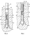
- the Spreading tongues 32 penetrate into the masonry 44 through a peripheral wall of the hole, as shown in FIG. 3.
- the expansion body 40 penetrates deeper into the hole, which can be seen by comparing FIGS. 2 and 3. However, this does not damage the anchoring of the expansion anchor 28 in the masonry 44.
- the expansion anchor 28 has reached its intended expansion position when the second depth marking 26 of the tool 10 is flush with a surface 48 of the masonry 44. This ensures that the expansion anchor 28 is anchored in the masonry 44 as intended.
- the shaft 38 of the expansion body 40 enters the cross-sectional constriction 42 of the anchor body 30, which forms a clamping connection with the shaft 38 and fixes the expansion body 40 in the anchor body 30, so that the expansion body 40 does not detach from the anchor body 30 and out the tongue 32 can move out.
- the cross-sectional constriction 42 forming the clamping connection reliably connects the expansion body 40 to the anchor body 30 when the anchor body 30 is widened by the expansion of its expansion tongues 32.
- the anchor body 28, as in the exemplary embodiment consists of a sheet metal formed into a hollow cylinder with a continuous longitudinal slot.
- the tool 10 can be pulled out and an object fastened to the masonry 44 by screwing a screw (not shown) into the internal thread 34.
- the axial distances from the ring step 22, the second depth marking 26 and the depth stop 16 on the mandrel 12 of the tool 10 are coordinated with one another in such a way that the expansion tongues 32 are spread out as intended when the expansion anchor 28 has been driven so far into a hole in the masonry 40 with the tool 10 is that its second depth mark 26 is flush with the surface 48 of the masonry 44 after the hole is driven in by the tool 10 has been made in the masonry 44 to the depth stop 16.
- the expansion anchor 28 is sunk a defined distance below the surface 48 of the masonry 44 so that it can be pulled by screwing in a screw when fastening an object in the direction of the surface 48 of the masonry 44 until it provides a firm hold.
- a screw 50 is screwed into the internal thread 34 of the expansion anchor 28 according to the invention.
- a deformable sleeve 54 made of plastic is pushed between the anchor body 30 and a head 52 of the screw 50.
- the length of the sleeve 54 corresponds to the distance of the ring step 22 from the second depth marking 26 on the tool 10.
- the screw 50 protrudes from the anchor body 30 to the extent that it corresponds to a sinking depth of the expansion anchor 28 below the surface 48 of the masonry 44 when the expansion anchor 28 is driven in with the tool 10 until its second depth marking 26 is flush with the surface 48 of the masonry 44 (see FIG. 3).
- the expansion anchor 28 according to the invention can be driven into the intended setting depth, for example by hammer blows on the head 52 of the screw 50, as with the tool 10.
- the expansion anchor 28 is placed in a hole which has been hammered into the masonry 44 through a wooden slat 56 with the tool 10 shown in FIG.
- the depth of the hole in the masonry 44 is therefore smaller by the thickness of the wooden slat 56 than when the hole is made with the tool 10 directly on the surface 48 of the masonry 44 without the wooden slat 56 being interposed.
- the expansion anchor 28 is inserted through the wooden slat 56 by hammer blows on the head 52 of the screw 50 in the same way as described with the tool 10 for FIGS. 2 and 3 into the hole in the masonry 44. Its setting depth in the masonry 44 is also reduced by the thickness of the wooden slat 56.
- the position of the expansion dowel 28 set in relation to the base of the hole is the same as when setting with the tool 10, ie the expansion tongues 32 of the expansion dowel 28 are spread out as intended and the expansion dowel 28 is anchored in the masonry 44.
- the anchor body 30 protrudes from the masonry 44 into the wooden slat 56, it is not sunk into the masonry.
- the reduced setting depth of the expansion anchor 28 is still sufficient to achieve the same holding values as when the expansion anchor 28 is fully sunk.
- the full expansion of the expansion tongues 32 is essential, as provided, in order to ensure the positive connection between expansion anchors 28 and 44.
- the screw 50 is only tightened in order to firmly attach the wooden slat 56 to the masonry 44.
- tightening the sleeve 54 is compressed, which does not interfere with the attachment of the wooden slat 56. Tightening the screw 50 takes place with a part of a full revolution or with a few revolutions, so it can be accomplished quickly.
- This embodiment of the expansion anchor 28 according to the invention has the advantage that an object such as the wooden slat 56 is positioned by pushing the expansion anchor 28 and inserting it into a hole in the masonry 44 on the masonry, the expansion anchor 28 is then placed on the head 52 of the screw 50 by hammer blows and the object 56 can be firmly attached to the masonry 44 by tightening the screw 50.
- the sleeve 54 can also have a length that corresponds to the distance between the ring step 22 and the second depth marking 26 on the tool 10 plus the thickness of the object 56 to be fastened.
- the expansion anchor 28 can be placed through the object 56 into a hole in the masonry 44, which has been produced by driving the tool 10 according to the invention into the masonry 44 until the depth stop 16 is placed on the surface 48 of the masonry 44.
- the sleeve 54 preferably has a specific color assigned to its length as a marking. This makes it easy to see which expansion plug 28 is suitable for an object 56 of a given thickness.
- the anchor body 30 can also have an external thread (not shown), onto which a nut is screwed in order to fasten an object.
- the expansion tongues 32 can be provided with a chamfer 58 in order to reduce the driving resistance of the expansion tongues and thus of the anchor body 30.
Landscapes
- Engineering & Computer Science (AREA)
- Mechanical Engineering (AREA)
- General Engineering & Computer Science (AREA)
- Dowels (AREA)
- Joining Of Building Structures In Genera (AREA)
- Processing Of Stones Or Stones Resemblance Materials (AREA)
- Retaining Walls (AREA)
Applications Claiming Priority (2)
| Application Number | Priority Date | Filing Date | Title |
|---|---|---|---|
| DE19612277A DE19612277A1 (de) | 1996-03-25 | 1996-03-28 | Lochschlag- und Ankersetzwerkzeug sowie mit dem Werkzeug setzbarer Anker für poröses Mauerwerk |
| DE19612277 | 1996-03-28 |
Publications (3)
| Publication Number | Publication Date |
|---|---|
| EP0803333A2 true EP0803333A2 (fr) | 1997-10-29 |
| EP0803333A3 EP0803333A3 (fr) | 1997-12-03 |
| EP0803333B1 EP0803333B1 (fr) | 2000-10-18 |
Family
ID=7789684
Family Applications (1)
| Application Number | Title | Priority Date | Filing Date |
|---|---|---|---|
| EP96118579A Expired - Lifetime EP0803333B1 (fr) | 1996-03-28 | 1996-11-20 | Outil pour percer un trou et insérer une cheville d'ancrage dans une maçonnerie poreuse |
Country Status (3)
| Country | Link |
|---|---|
| EP (1) | EP0803333B1 (fr) |
| AT (1) | ATE197009T1 (fr) |
| ES (1) | ES2152477T3 (fr) |
Family Cites Families (4)
| Publication number | Priority date | Publication date | Assignee | Title |
|---|---|---|---|---|
| DE8616598U1 (de) * | 1986-06-21 | 1987-04-30 | Drechsel, Rainer, 8500 Nürnberg | Vorsatzgerät zum Setzen von Schlagbolzen |
| DE3639838C2 (de) * | 1986-11-21 | 1995-07-13 | Hilti Ag | Treibdorn zum Verankern eines Dübels |
| EP0422377A1 (fr) * | 1989-10-10 | 1991-04-17 | fischerwerke Artur Fischer GmbH & Co. KG | Unité de montage avec boulon d'ancrage extensible et outil de montage |
| DE9002569U1 (de) * | 1990-03-06 | 1991-01-10 | Oettl, Reinhold, 7045 Nufringen | Dübel mit Setzwerkzeug |
-
1996
- 1996-11-20 EP EP96118579A patent/EP0803333B1/fr not_active Expired - Lifetime
- 1996-11-20 AT AT96118579T patent/ATE197009T1/de not_active IP Right Cessation
- 1996-11-20 ES ES96118579T patent/ES2152477T3/es not_active Expired - Lifetime
Non-Patent Citations (1)
| Title |
|---|
| None |
Also Published As
| Publication number | Publication date |
|---|---|
| EP0803333B1 (fr) | 2000-10-18 |
| ES2152477T3 (es) | 2001-02-01 |
| EP0803333A3 (fr) | 1997-12-03 |
| ATE197009T1 (de) | 2000-11-15 |
Similar Documents
| Publication | Publication Date | Title |
|---|---|---|
| DE2607338C2 (de) | Schlagdübel mit Spreizhülse und Spreizelement | |
| DE69301369T2 (de) | Betonanker | |
| DE2005467C3 (de) | Rohrförmige Dübelhülse aus Kunststoff | |
| DE3321623C2 (de) | Isolierplattendübel aus Kunststoff | |
| EP0375606A1 (fr) | Dispositif d'attache | |
| DE3429585A1 (de) | Aus einem kunststoffspreizduebel und einer befestigungsschraube bestehender befestigungssatz | |
| EP0724085A1 (fr) | Ancre de fixation à contre-dépouille avec engagement de forme | |
| DE3524284C2 (de) | Befestigungsvorrichtung | |
| DE19520130A1 (de) | Formschlüssig setzbarer Hinterschnitt-Anker | |
| EP0883755A1 (fr) | Cheville a percussion | |
| DE1450992A1 (de) | Duebel zur Befestigung von Gegenstaenden in Baustoffen | |
| DE3502607A1 (de) | Anker, insbesondere lastabhaengiger duebel | |
| EP0262444A1 (fr) | Dispositif d'ancrage, notamment cheville | |
| DE3533220A1 (de) | Spreizduebel | |
| DE2758091A1 (de) | Formschluessig setzbarer duebel | |
| DE19536786A1 (de) | Befestigungselement mit Spreizelement | |
| WO2004106754A1 (fr) | Ancre extensible en metal et son outil de mise en place | |
| DE19612277A1 (de) | Lochschlag- und Ankersetzwerkzeug sowie mit dem Werkzeug setzbarer Anker für poröses Mauerwerk | |
| WO1985003332A1 (fr) | Cheville de fermeture de moule pour du beton | |
| EP0803333A2 (fr) | Outil pour forer un trou et insèrer un boulon d'ancrage,et boulon d'ancrage apte à être inséré par l'outil dans une maçonnerie poreuse | |
| DE4020402A1 (de) | Einschlaganker | |
| EP0737817B1 (fr) | Dispositif de fixation avec élément d'expansion | |
| EP0290654A1 (fr) | Cheville à expansion pour l'ancrage à engagement positif dans un trou de forage | |
| DE3042463A1 (de) | Befestigungssatz, bestehend aus einem elastischen spreizduebel, sowie aus einem zur befestigung durch einschlagen vorgesehenen spreizelement | |
| DE4423234A1 (de) | Befestigungselement |
Legal Events
| Date | Code | Title | Description |
|---|---|---|---|
| PUAI | Public reference made under article 153(3) epc to a published international application that has entered the european phase |
Free format text: ORIGINAL CODE: 0009012 |
|
| PUAL | Search report despatched |
Free format text: ORIGINAL CODE: 0009013 |
|
| AK | Designated contracting states |
Kind code of ref document: A2 Designated state(s): AT BE CH DE DK ES FR GB IT LI NL PT |
|
| AK | Designated contracting states |
Kind code of ref document: A3 Designated state(s): AT BE CH DE DK ES FR GB IT LI NL PT |
|
| 17P | Request for examination filed |
Effective date: 19980418 |
|
| 17Q | First examination report despatched |
Effective date: 19990423 |
|
| RTI1 | Title (correction) |
Free format text: TOOL FOR MAKING A HOLE AND FOR INSERTING AN ANCHOR IN A POROUS MASONRY |
|
| GRAG | Despatch of communication of intention to grant |
Free format text: ORIGINAL CODE: EPIDOS AGRA |
|
| 17Q | First examination report despatched |
Effective date: 19990423 |
|
| GRAG | Despatch of communication of intention to grant |
Free format text: ORIGINAL CODE: EPIDOS AGRA |
|
| GRAH | Despatch of communication of intention to grant a patent |
Free format text: ORIGINAL CODE: EPIDOS IGRA |
|
| GRAH | Despatch of communication of intention to grant a patent |
Free format text: ORIGINAL CODE: EPIDOS IGRA |
|
| GRAA | (expected) grant |
Free format text: ORIGINAL CODE: 0009210 |
|
| PGFP | Annual fee paid to national office [announced via postgrant information from national office to epo] |
Ref country code: FR Payment date: 20000922 Year of fee payment: 5 |
|
| AK | Designated contracting states |
Kind code of ref document: B1 Designated state(s): AT BE CH DE DK ES FR GB IT LI NL PT |
|
| REF | Corresponds to: |
Ref document number: 197009 Country of ref document: AT Date of ref document: 20001115 Kind code of ref document: T |
|
| REG | Reference to a national code |
Ref country code: CH Ref legal event code: EP |
|
| PGFP | Annual fee paid to national office [announced via postgrant information from national office to epo] |
Ref country code: GB Payment date: 20001115 Year of fee payment: 5 |
|
| REF | Corresponds to: |
Ref document number: 59606027 Country of ref document: DE Date of ref document: 20001123 |
|
| PGFP | Annual fee paid to national office [announced via postgrant information from national office to epo] |
Ref country code: ES Payment date: 20001124 Year of fee payment: 5 |
|
| PGFP | Annual fee paid to national office [announced via postgrant information from national office to epo] |
Ref country code: AT Payment date: 20001127 Year of fee payment: 5 |
|
| PG25 | Lapsed in a contracting state [announced via postgrant information from national office to epo] |
Ref country code: LI Free format text: LAPSE BECAUSE OF NON-PAYMENT OF DUE FEES Effective date: 20001130 Ref country code: CH Free format text: LAPSE BECAUSE OF NON-PAYMENT OF DUE FEES Effective date: 20001130 Ref country code: BE Free format text: LAPSE BECAUSE OF NON-PAYMENT OF DUE FEES Effective date: 20001130 |
|
| PGFP | Annual fee paid to national office [announced via postgrant information from national office to epo] |
Ref country code: NL Payment date: 20001130 Year of fee payment: 5 |
|
| GBT | Gb: translation of ep patent filed (gb section 77(6)(a)/1977) |
Effective date: 20001130 |
|
| ITF | It: translation for a ep patent filed | ||
| PG25 | Lapsed in a contracting state [announced via postgrant information from national office to epo] |
Ref country code: PT Free format text: LAPSE BECAUSE OF FAILURE TO SUBMIT A TRANSLATION OF THE DESCRIPTION OR TO PAY THE FEE WITHIN THE PRESCRIBED TIME-LIMIT Effective date: 20010118 Ref country code: DK Free format text: LAPSE BECAUSE OF FAILURE TO SUBMIT A TRANSLATION OF THE DESCRIPTION OR TO PAY THE FEE WITHIN THE PRESCRIBED TIME-LIMIT Effective date: 20010118 |
|
| REG | Reference to a national code |
Ref country code: ES Ref legal event code: FG2A Ref document number: 2152477 Country of ref document: ES Kind code of ref document: T3 |
|
| ET | Fr: translation filed | ||
| BERE | Be: lapsed |
Owner name: FISCHERWERKE ARTUR FISCHER G.M.B.H. & CO. K.G. Effective date: 20001130 |
|
| REG | Reference to a national code |
Ref country code: CH Ref legal event code: PL |
|
| PLBE | No opposition filed within time limit |
Free format text: ORIGINAL CODE: 0009261 |
|
| STAA | Information on the status of an ep patent application or granted ep patent |
Free format text: STATUS: NO OPPOSITION FILED WITHIN TIME LIMIT |
|
| 26N | No opposition filed | ||
| PG25 | Lapsed in a contracting state [announced via postgrant information from national office to epo] |
Ref country code: GB Free format text: LAPSE BECAUSE OF NON-PAYMENT OF DUE FEES Effective date: 20011120 Ref country code: AT Free format text: LAPSE BECAUSE OF NON-PAYMENT OF DUE FEES Effective date: 20011120 |
|
| PG25 | Lapsed in a contracting state [announced via postgrant information from national office to epo] |
Ref country code: ES Free format text: LAPSE BECAUSE OF NON-PAYMENT OF DUE FEES Effective date: 20011121 |
|
| REG | Reference to a national code |
Ref country code: GB Ref legal event code: IF02 |
|
| PG25 | Lapsed in a contracting state [announced via postgrant information from national office to epo] |
Ref country code: NL Free format text: LAPSE BECAUSE OF NON-PAYMENT OF DUE FEES Effective date: 20020601 |
|
| GBPC | Gb: european patent ceased through non-payment of renewal fee |
Effective date: 20011120 |
|
| PG25 | Lapsed in a contracting state [announced via postgrant information from national office to epo] |
Ref country code: FR Free format text: LAPSE BECAUSE OF NON-PAYMENT OF DUE FEES Effective date: 20020730 |
|
| NLV4 | Nl: lapsed or anulled due to non-payment of the annual fee |
Effective date: 20020601 |
|
| REG | Reference to a national code |
Ref country code: FR Ref legal event code: ST |
|
| PGFP | Annual fee paid to national office [announced via postgrant information from national office to epo] |
Ref country code: DE Payment date: 20020903 Year of fee payment: 7 |
|
| REG | Reference to a national code |
Ref country code: FR Ref legal event code: ST |
|
| REG | Reference to a national code |
Ref country code: ES Ref legal event code: FD2A Effective date: 20021213 |
|
| PG25 | Lapsed in a contracting state [announced via postgrant information from national office to epo] |
Ref country code: DE Free format text: LAPSE BECAUSE OF NON-PAYMENT OF DUE FEES Effective date: 20040602 |
|
| PG25 | Lapsed in a contracting state [announced via postgrant information from national office to epo] |
Ref country code: IT Free format text: LAPSE BECAUSE OF NON-PAYMENT OF DUE FEES;WARNING: LAPSES OF ITALIAN PATENTS WITH EFFECTIVE DATE BEFORE 2007 MAY HAVE OCCURRED AT ANY TIME BEFORE 2007. THE CORRECT EFFECTIVE DATE MAY BE DIFFERENT FROM THE ONE RECORDED. Effective date: 20051120 |