EP0802833B1 - Vorrichtung und verfahren zum beschichten von garn - Google Patents
Vorrichtung und verfahren zum beschichten von garn Download PDFInfo
- Publication number
- EP0802833B1 EP0802833B1 EP95922884A EP95922884A EP0802833B1 EP 0802833 B1 EP0802833 B1 EP 0802833B1 EP 95922884 A EP95922884 A EP 95922884A EP 95922884 A EP95922884 A EP 95922884A EP 0802833 B1 EP0802833 B1 EP 0802833B1
- Authority
- EP
- European Patent Office
- Prior art keywords
- yarn
- container
- applicator
- coating material
- coating
- Prior art date
- Legal status (The legal status is an assumption and is not a legal conclusion. Google has not performed a legal analysis and makes no representation as to the accuracy of the status listed.)
- Expired - Lifetime
Links
- 238000000576 coating method Methods 0.000 title claims description 80
- 239000011248 coating agent Substances 0.000 title claims description 77
- 238000000034 method Methods 0.000 title claims description 13
- 239000000463 material Substances 0.000 claims description 44
- 238000011144 upstream manufacturing Methods 0.000 claims description 19
- 238000003860 storage Methods 0.000 claims description 12
- 230000009471 action Effects 0.000 claims description 10
- 239000007788 liquid Substances 0.000 claims description 9
- 238000006073 displacement reaction Methods 0.000 claims description 8
- 238000004891 communication Methods 0.000 claims description 5
- 230000008859 change Effects 0.000 claims description 4
- 239000000975 dye Substances 0.000 description 25
- 238000004043 dyeing Methods 0.000 description 25
- 241000628997 Flos Species 0.000 description 13
- 238000004519 manufacturing process Methods 0.000 description 4
- 235000013305 food Nutrition 0.000 description 3
- 239000002245 particle Substances 0.000 description 3
- 229920000642 polymer Polymers 0.000 description 3
- 238000000429 assembly Methods 0.000 description 2
- 230000000712 assembly Effects 0.000 description 2
- 230000001680 brushing effect Effects 0.000 description 2
- 238000004140 cleaning Methods 0.000 description 2
- 208000002925 dental caries Diseases 0.000 description 2
- 230000014759 maintenance of location Effects 0.000 description 2
- 239000000047 product Substances 0.000 description 2
- 230000000717 retained effect Effects 0.000 description 2
- 239000000126 substance Substances 0.000 description 2
- 238000009970 yarn dyeing Methods 0.000 description 2
- 229910001369 Brass Inorganic materials 0.000 description 1
- 208000018035 Dental disease Diseases 0.000 description 1
- 208000014151 Stomatognathic disease Diseases 0.000 description 1
- 238000010521 absorption reaction Methods 0.000 description 1
- 230000001580 bacterial effect Effects 0.000 description 1
- 239000010951 brass Substances 0.000 description 1
- 239000000919 ceramic Substances 0.000 description 1
- 230000001419 dependent effect Effects 0.000 description 1
- 235000004879 dioscorea Nutrition 0.000 description 1
- 208000007565 gingivitis Diseases 0.000 description 1
- 238000012986 modification Methods 0.000 description 1
- 230000004048 modification Effects 0.000 description 1
- 238000012544 monitoring process Methods 0.000 description 1
- 235000019645 odor Nutrition 0.000 description 1
- 230000003287 optical effect Effects 0.000 description 1
- 230000035515 penetration Effects 0.000 description 1
- 230000002093 peripheral effect Effects 0.000 description 1
- 230000007505 plaque formation Effects 0.000 description 1
- 230000008569 process Effects 0.000 description 1
- 238000005086 pumping Methods 0.000 description 1
- 238000002791 soaking Methods 0.000 description 1
- 239000007787 solid Substances 0.000 description 1
- 229910001220 stainless steel Inorganic materials 0.000 description 1
- 239000010935 stainless steel Substances 0.000 description 1
- 239000013589 supplement Substances 0.000 description 1
- 239000001993 wax Substances 0.000 description 1
Images


Classifications
-
- A—HUMAN NECESSITIES
- A61—MEDICAL OR VETERINARY SCIENCE; HYGIENE
- A61C—DENTISTRY; APPARATUS OR METHODS FOR ORAL OR DENTAL HYGIENE
- A61C15/00—Devices for cleaning between the teeth
- A61C15/04—Dental floss; Floss holders
- A61C15/041—Dental floss
-
- D—TEXTILES; PAPER
- D06—TREATMENT OF TEXTILES OR THE LIKE; LAUNDERING; FLEXIBLE MATERIALS NOT OTHERWISE PROVIDED FOR
- D06B—TREATING TEXTILE MATERIALS USING LIQUIDS, GASES OR VAPOURS
- D06B1/00—Applying liquids, gases or vapours onto textile materials to effect treatment, e.g. washing, dyeing, bleaching, sizing or impregnating
- D06B1/08—Applying liquids, gases or vapours onto textile materials to effect treatment, e.g. washing, dyeing, bleaching, sizing or impregnating from outlets being in, or almost in, contact with the textile material
-
- D—TEXTILES; PAPER
- D06—TREATMENT OF TEXTILES OR THE LIKE; LAUNDERING; FLEXIBLE MATERIALS NOT OTHERWISE PROVIDED FOR
- D06B—TREATING TEXTILE MATERIALS USING LIQUIDS, GASES OR VAPOURS
- D06B11/00—Treatment of selected parts of textile materials, e.g. partial dyeing
- D06B11/002—Treatment of selected parts of textile materials, e.g. partial dyeing of moving yarns
- D06B11/0026—Treatment of selected parts of textile materials, e.g. partial dyeing of moving yarns by spaced contacts with a member carrying a single treating material
-
- D—TEXTILES; PAPER
- D06—TREATMENT OF TEXTILES OR THE LIKE; LAUNDERING; FLEXIBLE MATERIALS NOT OTHERWISE PROVIDED FOR
- D06B—TREATING TEXTILE MATERIALS USING LIQUIDS, GASES OR VAPOURS
- D06B23/00—Component parts, details, or accessories of apparatus or machines, specially adapted for the treating of textile materials, not restricted to a particular kind of apparatus, provided for in groups D06B1/00 - D06B21/00
- D06B23/24—Means for regulating the amount of treating material picked up by the textile material during its treatment
Definitions
- the invention relates to an assembly for dyeing and/or coating selected portions of a yarn during the manufacture of dental floss yarn.
- it relates to an assembly and a method for dyeing and/or polymer coating selected portions of a yarn as the yarn is traveling at a high speed.
- the arrangement is particularly suitable for providing a dye and/or polymer coating to selected portions of a dental floss yarn.
- Tooth decay and dental disease can be caused by bacterial action resulting from the formation of plaque about the teeth and/or the entrapment of food particles between the teeth and interstices therebetween.
- the removal of plaque and entrapped food particles reduces the incidence of caries, gingivitis, and mouth odors as well as generally improving oral hygiene.
- Conventional brushing has been found to be inadequate for removing all entrapped food particles and plaque.
- dental flosses and tapes have been recommended.
- the term "dental floss”, as used herein, is defined to include both dental flosses, dental tapes and any similar article.
- dental flosses combining a thin "floss" portion and a thickened “brush” portion, together with a threader have been developed.
- the brush portion when drawn between tooth surfaces, has been found to provide an improved cleaning action which removes materials left by the floss portion, when used alone.
- the combination provides a substantially superior cleaning action.
- Such a device is described in U.S. Patent 4,008,727, for example.
- the complexity of this product requires that each floss segment be individually manufactured and that the product be packaged as bundles of the individual, separate floss articles.
- a continuous yarn having brush segments separated by thinner segments is disclosed in U.S. Patents 4,008,727 and 4,142,538.
- a problem arising in the manufacturing process of continuous floss brushes involves the application of coatings to the yarn.
- a variety of assemblies and methods are known for providing a yarn with a coating at spaced locations.
- a roller receives a coating from a supply, and provides a coating to the yarn as the yarn passes thereover in contact with the roller.
- the roller can be formed with only a partial section of a cylinder, such that only intermittent portions of the yarn contact the roller as the roller rotates.
- such an arrangement has been unsatisfactory in providing an adequate coating to the yarn, particularly in high speed manufacturing assemblies, for example, in which the yarn is traveling at over 100 meters/min., possibly even as high as 160 meters/min.
- GB-A- 2 079 189 discloses a coating applicator for applying a coating material to a yarn comprising a container with an open-ended slot having a base and an open end for receiving a yarn being defined by a pair of spaced apart sides extending from the base , the container having an upstream face being inclined inwardly towards the open end , and a downstream face.
- a coating applicator for applying a coating to a yarn, comprising a container, having at least one open-ended slot, each slot having a base and an open end for receiving a section of yarn, and said at least one slot (22) being defined by a pair of spaced apart, substantially parallel sides extending from the base and spaced sufficiently closely to each other to support a predetermined amount of a coating material by capillary action, wherein the container (12) has an upstream and a downstream face with at least the upstream face of the container (12) being inclined inwardly towards the open end.
- the slot may narrow from the upstream face to the downstream face.
- the open-ended slot may have a width sufficient to accommodate the thickness of the yarn, and the applicator further including a drive means for moving the length of yarn past the container, and displacement means for displacing at least a portion of the yarn toward the container to bring a section of the yarn into contact with the coating material.
- the displacement means may comprise a cam on a rotatable wheel, the cam having a cam surface positioned relative to the yarn such that, upon rotation of the wheel, the yarn is urged into contact with the coating material by the cam surface engaging the yarn, and when the cam surface is not in contact with the yarn, the yarn is not in contact with the coating material.
- the cam may be removably mounted on the wheel to permit replacement with differently sized or differently shaped cams.
- the applicator may include a guide means defining a guide slot located upstream of the container for aligning the yarn with the slot of the container.
- the guide means may have an inclined upstream face.
- the container typically defines a plurality of open-ended slots, each dimensioned to receive a section of yarn and to support a predetermined amount of the coating material.
- the guide means will then typically define a corresponding number of slots.
- the applicator may include a storage reservoir having an inlet, and an outlet in liquid communication with the container.
- the assembly may also include a pump means for pumping coating material to the storage reservoir, and a pump motor connected to the pump means for driving the pump means.
- the applicator may further include a supply controller means for controlling the pump means to replenish the storage reservoir at the same rate as that at which the coating material is removed from the container by the yarn.
- the supply controller means may be operable to control the pump motor.
- the applicator may also include a main supply reservoir in liquid communication with the inlet of the storage reservoir.
- the applicator may include a speed controller means for controlling the rotational speed of the wheel in proportion to the speed at which the length of yarn is moved past the container by the drive means.
- the speed at which the length of yarn is run past the container is determined and the displacement frequency at which the yarn is displaced into contact with the coating material, controlled, the frequency being controlled to change in proportion to the change in speed of the yarn.
- the coating material in the container may be replenished at the same rate as that at which it is removed from the container by the length of yarn.
- a coating material in the container may be replenished in proportion to the speed at which the length of yarn is run past the container.
- a plurality of yarn lengths may be run past the container simultaneously.
- coating will be used to refer to a variety of coating substances, e.g. dyes, polymer solutions, scented and unscented waxes and any other coating substance which may be applied to a yarn irrespective of its degree of penetration into the yarn.
- coating substances e.g. dyes, polymer solutions, scented and unscented waxes and any other coating substance which may be applied to a yarn irrespective of its degree of penetration into the yarn.
- the term "container” will be used to refer to any vessel or medium capable of supporting a liquid. This would, for example, also include a pad capable of soaking up and retaining a liquid.
- a plan view and side view of the yarn dyeing applicator of the present invention are respectively shown.
- a coating is applied to maintain the selected portions at a reduced diameter, and also to provide a dyed section to demarcate individual lengths.
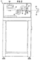
- the yarn dyeing applicator 10 includes a dyeing head or container 12, which provides dye at intermittent or spaced locations along a continuous length of yarn 13 as the yarn 13 travels in a direction indicated by arrow A.
- a dyeing head or container 12 Upstream of the dyeing head 12 is a cam roller 14 which is suitably driven by a drive means indicated generally by reference numeral 20.
- a deflection roller 16 is provided to assist in guiding the yarn 13, and to urge the yarn 13 against the cam roller 14.
- the apparatus is preferably utilized for simultaneous dyeing of a plurality of yarns 13, with the plurality of yarns 13 extending in the direction of arrow A, however a single yarn 13 could be dyed if desired.
- Fig. 2 it will become apparent that the yarns 13 pass over the deflection roller 16, and under the cam roller 14. At least one cam 15 is provided at a peripheral portion of the cam roller 14, such that as the roller 14 rotates, the yarns 13 will be deflected each time the cam 15 passes about the lowermost portion of the path of revolution of the cam 15, with the cam 15 contacting the yarns 13 and deflecting the yarns 13 downwardly. As the yarns 13 are deflected downwardly, they are coated or dyed by the dyeing head 12.
- the drive means 20 (Fig. 1) drives the cam roller 14 at a speed dependent upon the yarn travel speed, as well as the desired spacing between dyed portions. This is controlled by means of a magnetic sensor and controller arrangement as is described in greater detail below.
- the lengths of the dyed portions are determined by the configuration of the cam 15. For example, in the floss/brush context, it is desirable to provide selectively dyed portions having a length of approximately 3 inches, with 18 inches of the floss/brush disposed between respective dyed portions.
- the yarn 13 is driven by feed rollers (schematically indicated at 19) which also serve to control the tension of the yarn 13 downstream of the rollers 19.
- the drive means can include a separate motor, or a shaft extending from a common drive means which operates other components in a floss manufacturing system.
- the yarn tension during feeding is held at a predetermined level to control absorption of the dye.
- the tension typically is such as to maintain the yarn 13 at a reduced diameter.
- the tension must be below the tensile strength of the yarn 13 when deflected by the cam roller 14, such that the yarn 13 does not break during the dyeing operation.
- a guide means 18 is provided between the cam roller 14 and the dyeing head 12, such that the plurality of yarns 13 are properly positioned with respect to the dyeing head 12 as will become readily apparent hereinafter.
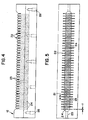
- Fig. 4 shows a front view of the dyeing head 12, in which a plurality of slots or grooves 22 are provided for a corresponding number of yarns 13 which are to be dyed simultaneously.
- 40 slots are provided, thereby allowing for the simultaneous selective dyeing of 40 yarns.
- the upper open ends of the slots or grooves 22 are defined by inclined surfaces 23 which support the yarns.
- the inclined surfaces 23 insure that any splices or other irregularities in the yarns 13 do not interrupt the process, e.g. by catching in the slots 22 and thereby breaking the yarn 13. In the event of an irregularity the inclined surfaces 23 will urge the yarn 13 upwardly to accommodate the irregularity.
- a plurality of bolt holes 26 are provided for mounting the dyeing head 12 by means of mounting bolts (not shown). By loosening the mounting bolts, and manipulating an adjustment screw 27 (Fig. 2) the height of the head 12 may be adjusted to increase or decrease the height of the head 12 relative to the yarn 13.
- Each slot 22 includes a liquid supply conduit 24 which supplies the dye upwardly into the slots 22, such that the slots 22 are constantly supplied with the dye.
- the supply conduits 24 are alternatingly staggered, thereby allowing the supply conduits 24 to be formed of a sufficient size constantly to flood the slots 22, while increasing the structural integrity of the dyeing head 12.
- the supply conduits 24 are formed with a diameter of 0.13 to 0.30 cm (0.05 to 0.12 inches), preferably 0.18 to 0.23 cm (0.07 to 0.09 inches), depending on the viscosity of the dye or coating material.
- the slots 22 may be formed of a sufficiently small width 21 (e.g.
- a pump may be controlled to supply the appropriate amount of dye to replenish the slots 22 at the same rate as that at which the dye is removed from the slots 22 by the yarns 13.
- a dye/coating can be provided for selected portions of yams by utilizing grooves which maintain the dye by capillary action.
- Capillary action depends upon two factors including: (1) the cohesion of the liquid molecules; and (2) the adhesion of the molecules to the surface of a solid, in this case the material of the dyeing head.
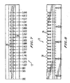
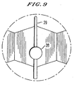
- the actual width of the grooves can vary as coatings or liquids to be applied to the yarn 13 vary, or if different materials for forming the dyeing head 12 are selected. Brass and stainless steel have, for instance, been found to work well as materials for the head 12. It will be appreciated that the positioning of the conduits 28 may take a variety of configurations. In one embodiment, illustrated in Figs. 7 to 9, found to work particularly well, the conduits 28 are spaced along a common straight line running slightly to one side of the longitudinal axis of the head 12, closer to its upstream end. This provides for a very uniform coating for all the yarns.
- conduits 28 have a diameter of 0.18 cm (0.07 inches) and the grooves 29 tapered from 0.045 cm (0.018 inches) at their upstream ends to 0.028-0.030 cm (0.011-0.012 inches) at their downstream ends. This tapered shape provides for better retention of the coating material.
- the supply conduits 24 are in flow communication with a dye storage reservoir 30, such that the supply conduits 24 supply the dye upwardly from the storage reservoir 30 to the slots 22.
- a ceramic piston pump 31 (Fig. 1) replenishes the reservoir 30 by continuously supplying dye from a main supply reservoir 32 to the reservoir 30 via a primary supply conduit (not shown).
- the primary supply conduit feeds the dye into the reservoir 30 by means of an inlet (not shown) provided in a lower wall of the reservoir 30.
- the conduits 24 are thus constantly supplied with dye and act as temporary storage reservoirs for supplying dye to the slots 22.
- the dye level in the conduits accordingly fluctuates as dye is continuously supplied from the reservoir 30 and is intermittently removed by the yarn 13.
- the upstream and downstream faces 33 of the dyeing head 12 are inclined, resulting in the hexagonal appearance of the open ends of the slots 22 when seen in plan view (Fig. 5).
- the inclined configuration serves to urge the yarn 13 upwardly in the event of an irregularity in the yarn 13, thus causing the yarn 13 to ride higher on the inclined surfaces 23 as was described above.
- the guide means 18 (disposed adjacent the dyeing head 12 as shown in Fig. 2) includes a comb-like structure, with a plurality of guide slots 34 corresponding to the number of slots provided in the dyeing head 12.
- the guide slots 34 have a width 35 which typically is larger than the width 21 of the slots 22 or the maximum width of the slots 29, such that the yarns can be guided by the guide slots 34, without rubbing excessively against the guide slots 34, and to accommodate small irregularities in the yarn.
- the yarns are thus suitably positioned with respect to the slots 22, 29 by the guide slots 34 of the comb-like structure, and by the inclined surfaces 23 of the dyeing head 12.
- a suitable width 35 of the guide slots 34 is for example 0.08 cm (.03 inches).
- the height 36 of the guide slots 34 is sufficient such that the yarns 13 are retained in the guide slots 34 irrespective of whether or not they are deflected by the cam 15.
- Mounting apertures 37 are provided such that the guide means 18 can be mounted directly on the dyeing head 12.
- the guide means 18 is shaped to be mounted closely adjacent to the dyeing head 12.
- the guide means 18 has an inclined upstream face 38 to allow the yarn to ride up on the guide means 18 in the event of an oversized irregularity in the yarn 13 being encountered.
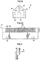
- the roller 14 includes a pair of end plates 40 secured to opposite ends of a roller cylinder having a surface 42.
- the roller 14 is maintained by a plurality of bolts 44. Three bolts 44 were found to be adequate in practice.
- the cam 15 in the form of a rod is secured to the end plates 40, by means of suitable fasteners. In the embodiment illustrated, spigot-like ends of the cam 15 are received in apertures in the plates 40 and retained by means of retention clips 45.
- the drive means 20 is controlled by a magnetic sensor and controller arrangement.
- a sensor (not shown) detects the yarn speed.
- a second magnetic sensor 54 monitors the rotational speed of the cam drive gear 56.
- the magnetic signal from the sensor 54 is converted into a 4-20 mA output signal which is, in turn, shaped by a programmable controller 58 (Figs. 2 and 3) and used to control the rotational speed of the cam roller 14.
- the pump 50 is controlled in a manner described below.
- the 4-20 mA output signal is sent to a stepper motor controller 60 (Fig. 3). This controls the speed of a stepper motor (not shown) which drives the pump 31.
- a digitally adjustable slope multiplier adjustable to 0.1% of full scale, allows adjustment of the stepper motor speed.
- the piston stroke and consequently the displacement of the piston may be adjusted.
- the amount of dye supplied by the pump 31 and the spacing between dyed portions can be controlled in sympathy with and as a function of the yarn speed.
- the replenishment of the dye in the slots can instead be related to the depletion of the dye from the slots by the yarns 13 by monitoring the level of the dye in the slots, for example by using an optical sensor.
- the signals from the sensor are then fed to a microprocessor to control the stepper motor speed.
- the cam 15 may be replaced with a suitably shaped cam.
- the length of application is fine-tuned by adjusting the height of the head 12 by loosening the mounting bolts and manipulating the adjustment screw 27 (Fig. 2).
Landscapes
- Engineering & Computer Science (AREA)
- Textile Engineering (AREA)
- Health & Medical Sciences (AREA)
- Epidemiology (AREA)
- Materials Engineering (AREA)
- Dentistry (AREA)
- Chemical & Material Sciences (AREA)
- Life Sciences & Earth Sciences (AREA)
- Animal Behavior & Ethology (AREA)
- General Health & Medical Sciences (AREA)
- Public Health (AREA)
- Veterinary Medicine (AREA)
- Treatment Of Fiber Materials (AREA)
Claims (17)
- Auftrag-Appliziereinrichtung(10) zum Auftragen einer Beschichtungsmasse auf Garn (13), aufweisend einen Behälter (12) mit mindestens einem offenen Schlitz (22), wobei jeder Schlitz (22) eine Unterseite und ein offenes Ende zur Aufnahme eines Garnabschnittes (13) hat und dieser mindestens eine Schlitz (22) durch ein Paar beabstandete, weitgehend parallele Seiten begrenzt ist, die sich von der Unterseite erstrecken und ausreichend dicht beieinander sind, um eine vorbestimmte Menge einer Beschichtungsmasse durch Kapillarwirkung zu tragen, wobei der Behälter (12) eine in Stromrichtung aufwärts gerichtete und eine in Stromrichtung abwärts gerichtete Fläche hat, wobei mindestens die in Stromrichtung abwärts gerichtete Fläche des Behälters (12) nach innen zum offenen Ende hin geneigt ist.
- Auftrag-Appliziereinrichtung (10) nach Anspruch 1, bei welcher der Schlitz (22) von der in Stromrichtung aufwärts gerichteten Fläche zu der in Stromrichtung abwärts gerichteten Fläche schmaler wird.
- Auftrag-Appliziereinrichtung (10) nach Anspruch 1 oder 2, bei welcher der Schlitz (22) mit dem offenen Ende eine ausreichende Breite (21) hat, um die Dicke des Garns (13) aufzunehmen, wobei in die Appliziereinrichtung (10) ferner eine Antriebsvorrichtung (20) einbezogen ist, um die Länge des Garns (13) hinter den Behälter (12) zu fördern, sowie eine Vorrichtung zum Auslenken, um mindestens einen Abschnitt des Garns (13) in Richtung auf den Behälter (12) zu lenken, um einen Abschnitt des Garns (13) mit der Beschichtungsmasse in Kontakt zu bringen.
- Auftrag-Appliziereinrichtung (10) nach Anspruch 3, bei welcher die Vorrichtung zum Auslenken eine Nocke (15) auf einem rotationsfähigen Rad (14) aufweist, wobei die Nocke (15) eine Nockenoberfläche hat, die im Bezug auf das Garn (13) derart angeordnet ist, dass bei Rotation des Rads (14) das Garn (13) in Kontakt mit der Beschichtungsmasse über die Nockenoberfläche gebracht wird, die in das Garn (13) eingreift und, wobei, wenn die Nockenoberfläche nicht in Kontakt mit dem Garn (13) ist, das Garn sich nicht im Kontakt mit der Beschichtungsmasse befindet.
- Auftrag-Appliziereinrichtung (10) nach Anspruch 4, bei welcher die Nocke (15) auf dem Rad (14) abnehmbar angebracht ist.
- Auftrag-Appliziereinrichtung (10) nach Anspruch 4 oder 5, bei welcher in die Appliziereinrichtung (10) ein Drehzahlregler (54,58) einbezogen ist, um die Drehzahl des Rads (14) proportional zur Geschwindigkeit zu regeln, mit der die Länge des Garns (13) mit Hilfe der Antriebvorrichtung (20) hinter den Behälter (12) gefördert wird.
- Auftrag-Appliziereinrichtung (10) nach Anspruch nach einem der vorgenannten Ansprüche, bei welcher in die Appliziereinrichtung (10) ferner eine Führungsvorrichtung (18) einbezogen ist, die einen Führungsschlitz (34) festlegt, der dem Behälter (12) nachgeschaltet ist, um das Garn (13) mit dem Schlitz (22) des Behälters (12) auszurichten.
- Auftrag-Appliziereinrichtung (10) nach Anspruch Anspruch 7, bei welcher die Führungsvorrichtung (18) eine in Stromrichtung aufwärts geneigte Fläche (38) hat.
- Auftrag-Appliziereinrichtung (10) nach einem der vorgenannten Ansprüche, bei welcher die Behältervorrichtung (12) eine Vielzahl von Schlitzen mit offenem Ende (22) begrenzt, die jeweils so bemessen sind, dass sie einen Abschnitt des Garns (13) aufnehmen und eine Vorrichtung der Menge der Beschichtungsmasse tragen.
- Auftrag-Appliziereinrichtung (10) nach einem der vorgenannten Ansprüche, wobei in die Appliziereinrichtung (10) ein Vorratsbehälter (30) einbezogen ist, der über einen Einlass und einen Auslass in Flüssigkeit-kommunizierender Verbindung mit dem Behälter (12) verfügt.
- Auftrag-Appliziereinrichtung (10) nach Anspruch 10, wobei in die Appliziereinrichtung (10) eine Pumpenvorrichtung (31) einbezogen ist, die mit dem Vorratsbehälter (30) verbunden ist, um den Vorratsbehälter (30) zur Beschichtungsmasse zuzuführen, sowie ein Pumpenmotor, der mit der Pumpenvorrichtung (31) verbunden ist, um die Pumpenvorrichtung (31) anzutreiben.
- Auftrag-Appliziereinrichtung (10) nach Anspruch 11, wobei in die Appliziereinrichtung (10) ein Zufuhrregler zum Regeln der Pumpenvorrichtung (31) einbezogen ist, um den Vorratsbehälter (38) mit der gleichen Geschwindigkeit nachzufüllen, mit der die Beschichtungsmasse aus dem Behälter (12) durch das Garn (13) entnommen wird.
- Auftrag-Appliziereinrichtung (10) nach einem der Ansprüche 10 bis 12, wobei in die Appliziereinrichtung (10) ein Hauptversorgungsbehälter (32) in Flüssigkeit-kommunizierender Verbindung mit dem Einlass des Vorratsbehälters (30) verbunden ist.
- Verfahren zum Aufbringen einer Beschichtungsmasse auf mindestens einer Länge von Garn an intermittierenden Stellen entlang der Länge des Garns, welches Verfahren umfasst: die Garnlänge hinter einen Behälter laufen lassen, der eine Menge der Beschichtungsmasse enthält, und intermittierend mindestens einen Teil der Garnlänge in Richtung auf den Behälter auslenken, wobei jede Auslenkung einen Abschnitt des Garns in Kontakt mit der Beschichtungsmasse bringt, um intermittierend beschichtete Abschnitte zu erzeugen; wobei der Behälter mindestens einen Schlitz mit offenem Ende aufweist, jeder Schlitz eine Unterseite und ein offenes Ende zum Aufnehmen eines Garnabschnittes aufweist und der mindestens eine Schlitz (22) durch ein Paar beabstandete, weitgehend paralleler Seiten begrenzt ist, die sich von der Unterseite erstrecken und ausreichend eng beieinander sind, um eine vorbestimmte Menge einer Beschichtungsmasse durch Kapillarwirkung zu tragen, wobei der Behälter eine in Stromrichtung aufwärts gerichtete und eine in Stromrichtung abwärts gerichtete Fläche hat, wobei mindestens die Stromrichtung abwärts gerichtete Fläche des Behälters nach innen zum Offenen Ende hin geneigt ist; und wobei in das Verfahren ferner das Regeln der Spannung des Gamabschnittes einbezogen ist, der in Kontakt mit der Beschichtungsmasse ausgelenkt ist, während sich der Garnabschnitt mit der Beschichtungsmasse in Kontakt befindet; Bestimmen der Geschwindigkeit, mit der die Länge des Garns hinter den Behälter gefördert wird, und Regeln der Frequenz des Auslenkens, in der das Garn mit der Beschichtungsmasse ausgelenkt wird, wobei die Frequenz so geregelt wird, dass sie sich proportional mit der Änderung der Geschwindigkeit des Garns ändert.
- Verfahren nach Anspruch 14, worin das Auffüllen der Beschichtungsmasse in dem Behälter mit der gleichen Geschwindigkeit einbezogen ist, wie diese aus dem Behälter durch die Länge des Garns entnommen wird.
- Verfahren nach Anspruch 14, worin das Auffüllen der Beschichtungsmasse in den Behälter proportional zur Geschwindigkeit einbezogen ist, mit der die Länge des Garns hinter den Behälter gefördert wird.
- Verfahren nach Anspruch 16, bei welchem eine Vielzahl von Garnlängen gleichzeitig hinter den Behälter gefördert wird.
Applications Claiming Priority (3)
| Application Number | Priority Date | Filing Date | Title |
|---|---|---|---|
| US08/249,516 US5501734A (en) | 1992-02-06 | 1994-05-26 | Yarn coating assembly and applicator |
| US249516 | 1994-05-26 | ||
| PCT/US1995/006567 WO1995032808A1 (en) | 1994-05-26 | 1995-05-23 | Yarn coating assembly and method |
Publications (3)
| Publication Number | Publication Date |
|---|---|
| EP0802833A1 EP0802833A1 (de) | 1997-10-29 |
| EP0802833A4 EP0802833A4 (de) | 1999-05-12 |
| EP0802833B1 true EP0802833B1 (de) | 2003-04-09 |
Family
ID=22943800
Family Applications (1)
| Application Number | Title | Priority Date | Filing Date |
|---|---|---|---|
| EP95922884A Expired - Lifetime EP0802833B1 (de) | 1994-05-26 | 1995-05-23 | Vorrichtung und verfahren zum beschichten von garn |
Country Status (8)
| Country | Link |
|---|---|
| US (1) | US5501734A (de) |
| EP (1) | EP0802833B1 (de) |
| AU (1) | AU700824B2 (de) |
| BR (1) | BR9507763A (de) |
| CA (1) | CA2190733A1 (de) |
| DE (1) | DE69530324T2 (de) |
| WO (1) | WO1995032808A1 (de) |
| ZA (1) | ZA954131B (de) |
Families Citing this family (20)
| Publication number | Priority date | Publication date | Assignee | Title |
|---|---|---|---|---|
| DE4418144A1 (de) * | 1994-05-25 | 1995-11-30 | Akzo Nobel Nv | Vorrichtung zum Beaufschlagen einer Fadenschar mit Flüssigkeit |
| US5679158A (en) * | 1996-03-19 | 1997-10-21 | Basf Corporation | Finish nozzle and application assembly for a synthetic filament spinning apparatus |
| FR2748756B1 (fr) * | 1996-05-20 | 1998-07-17 | Superba Sa | Tete d'enduction de teinture par depot de bain sur fils en mouvement |
| US5755243A (en) * | 1996-06-27 | 1998-05-26 | Gillette Canada, Inc. | Dental floss with thermoplastic coating |
| US6067928A (en) * | 1997-10-02 | 2000-05-30 | Basf Corporation | Filament guide assembly especially useful in combination with filament finish applicators |
| US6436484B1 (en) | 1997-12-09 | 2002-08-20 | Coats American, Inc. | Processes for coating sewing thread |
| MXPA01011325A (es) * | 1999-05-07 | 2002-06-04 | Designetics | Estacion automatizada de aplicacion de material primordial. |
| US6254921B1 (en) * | 1999-12-08 | 2001-07-03 | Surmodics, Inc. | Coating process and apparatus |
| US6737113B2 (en) * | 2001-01-10 | 2004-05-18 | 3M Innovative Properties Company | Method for improving the uniformity of a wet coating on a substrate using pick-and-place devices |
| US6814807B1 (en) | 2001-09-19 | 2004-11-09 | Georgia Tech Research Corp. | Apparatus for single-end slashing |
| EP1484439A1 (de) * | 2003-06-06 | 2004-12-08 | Picanol N.V. | Verfahren und Vorrichtung zum Auftragen von mehreren Substanzen auf ein Garn |
| US20090035574A1 (en) * | 2007-07-31 | 2009-02-05 | Peter Gable | Fiber Coating System |
| US20100028527A1 (en) * | 2008-07-31 | 2010-02-04 | Harold Ochs | Process for Coating Dental Tape |
| US20100024722A1 (en) * | 2008-07-31 | 2010-02-04 | Harold Ochs | Apparatus for Coating Dental Tape |
| US8316865B2 (en) | 2008-07-31 | 2012-11-27 | Mcneil-Ppc, Inc. | Process for winding dental tape |
| US20100024721A1 (en) * | 2008-07-31 | 2010-02-04 | Harold Ochs | Apparatus for Coating Dental Tape |
| WO2010065946A2 (en) | 2008-12-06 | 2010-06-10 | 3Ip, Pllc | Improved heat transfer between tracer and pipe |
| MX350644B (es) * | 2010-02-08 | 2017-09-05 | The Procter & Gamble Company * | Hilo dental recubierto de variabilidad reducida. |
| CN111593520B (zh) * | 2020-03-26 | 2022-09-02 | 南通隆彩纺织科技有限公司 | 一种用于花色纱的段染设备 |
| US12188729B2 (en) * | 2020-10-08 | 2025-01-07 | Controls Southeast, Inc. | Adjustable heat transfer element |
Family Cites Families (71)
| Publication number | Priority date | Publication date | Assignee | Title |
|---|---|---|---|---|
| US174619A (en) * | 1876-03-14 | Improvement in tooth-picks | ||
| US290678A (en) * | 1883-12-25 | gourdiat | ||
| US660943A (en) * | 1900-03-13 | 1900-10-30 | Hermann Bauermeister | Method of preparing dental remedies. |
| DE560937C (de) * | 1931-08-19 | 1932-10-08 | Algemeene Kunstzijde Unie N V | Verfahren und Vorrichtung zum Impraegnieren von laufenden Textilfaeden, insbesondere zum Schlichten oder OElen von Kunstseide |
| US2325129A (en) * | 1941-11-01 | 1943-07-27 | Du Pont | Yarn finishing |
| US2667443A (en) * | 1949-05-14 | 1954-01-26 | Johnson & Johnson | Dental floss |
| US2700636A (en) * | 1949-05-14 | 1955-01-25 | Johnson & Johnson | Gum-impregnated dental floss |
| US2748781A (en) * | 1953-08-24 | 1956-06-05 | Collat Edgar | Means for dental hygiene |
| BE648050A (de) * | 1963-05-17 | |||
| US3492131A (en) * | 1966-04-18 | 1970-01-27 | Searle & Co | Peptide sweetening agents |
| US3434189A (en) * | 1966-08-02 | 1969-03-25 | Klinger Mfg Co Ltd | Method of continuously dyeing and stretching undrawn yarn |
| US3800046A (en) * | 1967-04-17 | 1974-03-26 | Searle & Co | Artificially sweetened consumable products |
| US3507250A (en) * | 1967-11-22 | 1970-04-21 | Monsanto Co | Liquid applicator |
| US3615671A (en) * | 1968-04-19 | 1971-10-26 | Gen Foods Corp | Dry food products in spun filaments and method of making same |
| CH504900A (de) * | 1969-09-11 | 1971-03-31 | Rieter Ag Maschf | Vorrichtung zum Behandeln eines Fadens mit Flüssigkeit |
| US3642491A (en) * | 1970-01-12 | 1972-02-15 | Searle & Co | Artificially sweetened consumable products |
| US3699979A (en) * | 1971-04-08 | 1972-10-24 | Indiana University Foundation | Impregnated article for cleaning the interproximal surfaces of the teeth |
| US3906757A (en) * | 1971-06-14 | 1975-09-23 | Unitika Ltd | Apparatus for continuous dyeing of yarns |
| US3896824A (en) * | 1971-08-27 | 1975-07-29 | Thomas F Thornton | Teeth cleaning |
| NL7212888A (de) * | 1971-09-29 | 1973-04-02 | ||
| US3771536A (en) * | 1972-05-08 | 1973-11-13 | W Dragan | Dental floss and method of making same |
| US3830246A (en) * | 1972-05-26 | 1974-08-20 | B Gillings | Fluoride impregnated dental floss |
| US3838702A (en) * | 1972-10-03 | 1974-10-01 | Standard Oil Co | Dental floss |
| US3837351A (en) * | 1973-02-15 | 1974-09-24 | T Thornton | Interdental tooth cleaner and method for making same |
| US3897795A (en) * | 1973-07-30 | 1975-08-05 | Centrix Inc | Dental floss and method of making same |
| GB1449190A (en) * | 1973-12-15 | 1976-09-15 | Bsg Designs | Colouration of a substrate |
| US3923003A (en) * | 1974-05-06 | 1975-12-02 | Southwire Co | Production of flooded multistrand cable |
| US3991704A (en) * | 1974-07-18 | 1976-11-16 | Loctite Corporation | Coating apparatus |
| US3939261A (en) * | 1974-08-30 | 1976-02-17 | Colgate-Palmolive Company | Flavored dentifrice |
| US3943949A (en) * | 1974-11-26 | 1976-03-16 | Johnson & Johnson | Flavored dental articles |
| US4029113A (en) * | 1975-02-20 | 1977-06-14 | William Cecil Guyton | Waxed dental textile material and method of preparing and using the same |
| US4013435A (en) * | 1975-03-12 | 1977-03-22 | Owens-Corning Fiberglas Corporation | Production of organic fibers with inorganic cores |
| US4008727A (en) * | 1975-05-19 | 1977-02-22 | Thornton Thomas F | Interproximal space tooth cleaner |
| US3972214A (en) * | 1975-06-02 | 1976-08-03 | Bleckmann & Co. | Machine for manufacturing wire coils |
| US4047271A (en) * | 1976-01-02 | 1977-09-13 | Interdye Technology Corporation | Method for space dyeing yarn |
| US4033365A (en) * | 1976-01-23 | 1977-07-05 | Johnson & Johnson | Flavored dental articles |
| US4073260A (en) * | 1976-04-19 | 1978-02-14 | British Steel Corporation | Apparatus for removing cross welds from metal tubes and marking the same |
| DE2635341A1 (de) * | 1976-08-03 | 1978-02-09 | Berliner Maschinenbau Ag | Vorrichtung zum benetzen und texturieren von einem oder mehreren, aus einer mehrzahl von synthetischen filamenten gebildeten garnen |
| CA1087712A (en) * | 1976-11-01 | 1980-10-14 | Northern Telecom Limited | Control for wire coating line |
| US4142538A (en) * | 1977-01-17 | 1979-03-06 | Thornton Thomas F | Different stiffness continuous length teeth cleaner |
| US4158976A (en) * | 1977-10-13 | 1979-06-26 | Meyer, Roth & Pastor Maschinenfabrik Gmbh | Discharge device for a wire cutter |
| US4153961A (en) * | 1977-11-18 | 1979-05-15 | Cleveland J B | Method and apparatus for randomly dyeing textile yarns in a continuous system |
| US4291017A (en) * | 1979-11-19 | 1981-09-22 | Dental Concepts, Inc. | Method for limiting adherence of plaque and dental composition therefor |
| GB2079189B (en) * | 1980-07-09 | 1984-01-11 | Heberlein & Co Ag | Moistening textile yarns |
| US4397164A (en) * | 1980-09-15 | 1983-08-09 | E. I. Du Pont De Nemours And Company | Apparatus for applying finish to a yarn |
| US4350311A (en) * | 1980-11-17 | 1982-09-21 | Pokhodnya Igor K | Wire coiling machine |
| IT8149758A0 (it) * | 1981-11-23 | 1981-11-23 | Romualdo Minozzi | Filo interdentale ad azione antisettica et/aut antiplacca batterica ed anticarie |
| US4414990A (en) * | 1982-04-02 | 1983-11-15 | Johnson & Johnson Products, Inc. | Fluoridated dental articles |
| US4638823A (en) * | 1983-03-14 | 1987-01-27 | Newman Michael G | Fluoride-coated dental floss |
| US4548219A (en) * | 1983-03-14 | 1985-10-22 | Newman Michael G | Fluoride-coated dental floss |
| US4789858A (en) * | 1984-06-12 | 1988-12-06 | Taliq Corporation | Multifunction switch incorporating NCAP liquid crystal |
| US4627975A (en) * | 1984-12-21 | 1986-12-09 | Ici Americas Inc. | Dental floss dentifrice formulation and method of treating teeth, mouth and throat therewith to reduce plaque accumulation and irritation |
| US4605573A (en) * | 1985-02-11 | 1986-08-12 | Celanese Corporation | Methods and apparatus for applying a finish liquid to a bundle of filmentary material |
| US4952392A (en) * | 1986-03-17 | 1990-08-28 | Peri-Oral Dental Products, Inc. | Use of periwinkle in oral hygiene |
| JPH0684230B2 (ja) * | 1986-04-28 | 1994-10-26 | 日機電装株式会社 | 定尺位置決め装置 |
| CH672445A5 (de) * | 1987-02-27 | 1989-11-30 | Hratch Boyadjian | |
| US4738866A (en) * | 1987-03-20 | 1988-04-19 | Burlington Industries, Inc. | Apparatus and method for determining whether an adequate amount of sizing has been applied to yarn ends |
| US4817643A (en) * | 1987-07-30 | 1989-04-04 | Olson Mary Lou C | Chinese finger cuff dental floss |
| US4891960A (en) * | 1988-01-26 | 1990-01-09 | E. I. Du Pont De Nemours And Company | Yarn finish applicator |
| US4986288A (en) * | 1988-03-23 | 1991-01-22 | Colgate-Palmolive Company | Dental floss and picks |
| US5033488A (en) * | 1988-03-29 | 1991-07-23 | Colgate-Palmolive Co. | Dental floss |
| US4908153A (en) * | 1988-05-06 | 1990-03-13 | Service Tool Die & Mfg. Company | Transport apparatus for electrocoating machines |
| GB8819873D0 (en) * | 1988-08-22 | 1988-09-21 | Westone Prod Ltd | Dental floss & tape |
| JPH0663171B2 (ja) * | 1988-09-06 | 1994-08-17 | 吉田工業株式会社 | 長尺被染物の色替え連続染色方法 |
| US4911927A (en) * | 1988-11-14 | 1990-03-27 | Hill Ira D | Method and apparatus for adding chemotherapeutic agents to dental floss |
| US4926661A (en) * | 1989-03-15 | 1990-05-22 | E. I. Du Pont De Nemours And Company | Yarn finish applicator |
| US5063948A (en) * | 1990-04-11 | 1991-11-12 | Lloyd O H Perry | Bristled dental floss |
| US4974615A (en) * | 1989-07-26 | 1990-12-04 | Doundoulakis George J | Elastic filament for oral hygiene |
| US5072691A (en) * | 1989-10-30 | 1991-12-17 | Strandberg Jr Charles F | Apparatus for monitoring size encapsulation of yarn on a slasher |
| US4998978A (en) * | 1990-01-10 | 1991-03-12 | Varum Shirley B | Tooth cleaning strip |
| US5181401A (en) * | 1991-01-08 | 1993-01-26 | Basf Corporation | Yarn coating applicator |
-
1994
- 1994-05-26 US US08/249,516 patent/US5501734A/en not_active Expired - Lifetime
-
1995
- 1995-05-19 ZA ZA954131A patent/ZA954131B/xx unknown
- 1995-05-23 EP EP95922884A patent/EP0802833B1/de not_active Expired - Lifetime
- 1995-05-23 WO PCT/US1995/006567 patent/WO1995032808A1/en not_active Ceased
- 1995-05-23 DE DE69530324T patent/DE69530324T2/de not_active Expired - Lifetime
- 1995-05-23 AU AU27620/95A patent/AU700824B2/en not_active Ceased
- 1995-05-23 CA CA002190733A patent/CA2190733A1/en not_active Abandoned
- 1995-05-23 BR BR9507763A patent/BR9507763A/pt not_active IP Right Cessation
Also Published As
| Publication number | Publication date |
|---|---|
| ZA954131B (en) | 1996-01-19 |
| EP0802833A4 (de) | 1999-05-12 |
| US5501734A (en) | 1996-03-26 |
| AU700824B2 (en) | 1999-01-14 |
| BR9507763A (pt) | 1997-09-02 |
| AU2762095A (en) | 1995-12-21 |
| CA2190733A1 (en) | 1995-12-07 |
| WO1995032808A1 (en) | 1995-12-07 |
| EP0802833A1 (de) | 1997-10-29 |
| DE69530324D1 (de) | 2003-05-15 |
| DE69530324T2 (de) | 2004-02-12 |
Similar Documents
| Publication | Publication Date | Title |
|---|---|---|
| EP0802833B1 (de) | Vorrichtung und verfahren zum beschichten von garn | |
| US5368893A (en) | Method and apparatus for coating a material web, especially a paper web or cardboard web | |
| RU2108956C1 (ru) | Устройство и способ нанесения клея на сердечник для намотки рулонного материала | |
| US4167914A (en) | Rotating rod, rotating press roll nip coating apparatus | |
| JP2901661B2 (ja) | 移動するウエブを塗布する装置 | |
| EP0802773B1 (de) | Methode und anordnung zum bauchen von zahnseide | |
| CN116133971A (zh) | 卷绕机 | |
| US5858090A (en) | Apparatus for the application of a liquid or pasty medium onto a moving material web, in particular of paper or board | |
| SE501564C2 (sv) | Bestrykningsanordning för en eller tvåsidig bestrykning av en löpande bana | |
| EP0796662B1 (de) | Verfahren und Vorrichtung zur Beschichtung eines flüssigen Materials auf einem beweglichen Substrat | |
| US7056384B2 (en) | Strip brush bowling lane dressing application mechanism | |
| EP2149632B1 (de) | Verfahren zum Beschichten eines Zahnbandes | |
| WO1995012031A1 (en) | Method of minimizing skip coating on a paper web | |
| JPH10216600A (ja) | 特に紙またはボール紙からなる、走行する材料ウェブに、液体状またはペースト状媒体を直接的または間接的に塗布する装置 | |
| US3877414A (en) | Apparatus for coating wire filament with liquid | |
| EP1127667B1 (de) | Vorrichtung zum Glasieren von keramischen Fliesen | |
| EP0026922B1 (de) | Vorrichtung zum Auftragen von Flüssigkeit auf Textilgarne | |
| US4051651A (en) | Method and apparatus for wetting thread in a double twist twisting spindle | |
| CA2347783A1 (en) | Battery cell coating apparatus and method | |
| CA2198264A1 (en) | Method and device for coating strips of material, in particular paper orcardboard | |
| US4068502A (en) | Apparatus for multicolor dyeing of textile yarns | |
| EP2149631B1 (de) | Vorrichtung und Verfahren zum Beschichten eines Zahnbandes | |
| US5074776A (en) | Paper-coating | |
| EP0185711A1 (de) | Regelbare auftragung einer flüssigkeit auf ein garn | |
| US5052334A (en) | Coating applicator for moving fibers |
Legal Events
| Date | Code | Title | Description |
|---|---|---|---|
| PUAI | Public reference made under article 153(3) epc to a published international application that has entered the european phase |
Free format text: ORIGINAL CODE: 0009012 |
|
| 17P | Request for examination filed |
Effective date: 19961223 |
|
| AK | Designated contracting states |
Kind code of ref document: A1 Designated state(s): DE GB IE |
|
| A4 | Supplementary search report drawn up and despatched |
Effective date: 19990331 |
|
| AK | Designated contracting states |
Kind code of ref document: A4 Designated state(s): DE GB IE |
|
| 17Q | First examination report despatched |
Effective date: 20000515 |
|
| GRAH | Despatch of communication of intention to grant a patent |
Free format text: ORIGINAL CODE: EPIDOS IGRA |
|
| GRAH | Despatch of communication of intention to grant a patent |
Free format text: ORIGINAL CODE: EPIDOS IGRA |
|
| GRAA | (expected) grant |
Free format text: ORIGINAL CODE: 0009210 |
|
| RAP1 | Party data changed (applicant data changed or rights of an application transferred) |
Owner name: THE GILLETTE COMPANY |
|
| AK | Designated contracting states |
Designated state(s): DE GB IE |
|
| REG | Reference to a national code |
Ref country code: GB Ref legal event code: FG4D |
|
| REG | Reference to a national code |
Ref country code: IE Ref legal event code: FG4D |
|
| PLBE | No opposition filed within time limit |
Free format text: ORIGINAL CODE: 0009261 |
|
| STAA | Information on the status of an ep patent application or granted ep patent |
Free format text: STATUS: NO OPPOSITION FILED WITHIN TIME LIMIT |
|
| 26N | No opposition filed |
Effective date: 20040112 |
|
| PGFP | Annual fee paid to national office [announced via postgrant information from national office to epo] |
Ref country code: IE Payment date: 20110427 Year of fee payment: 17 |
|
| PGFP | Annual fee paid to national office [announced via postgrant information from national office to epo] |
Ref country code: GB Payment date: 20110421 Year of fee payment: 17 |
|
| PGFP | Annual fee paid to national office [announced via postgrant information from national office to epo] |
Ref country code: DE Payment date: 20110531 Year of fee payment: 17 |
|
| GBPC | Gb: european patent ceased through non-payment of renewal fee |
Effective date: 20120523 |
|
| REG | Reference to a national code |
Ref country code: IE Ref legal event code: MM4A |
|
| REG | Reference to a national code |
Ref country code: DE Ref legal event code: R119 Ref document number: 69530324 Country of ref document: DE Effective date: 20121201 |
|
| PG25 | Lapsed in a contracting state [announced via postgrant information from national office to epo] |
Ref country code: IE Free format text: LAPSE BECAUSE OF NON-PAYMENT OF DUE FEES Effective date: 20120523 Ref country code: GB Free format text: LAPSE BECAUSE OF NON-PAYMENT OF DUE FEES Effective date: 20120523 |
|
| PG25 | Lapsed in a contracting state [announced via postgrant information from national office to epo] |
Ref country code: DE Free format text: LAPSE BECAUSE OF NON-PAYMENT OF DUE FEES Effective date: 20121201 |