EP0802827B1 - Zerstäubungsdüse - Google Patents
Zerstäubungsdüse Download PDFInfo
- Publication number
- EP0802827B1 EP0802827B1 EP96901030A EP96901030A EP0802827B1 EP 0802827 B1 EP0802827 B1 EP 0802827B1 EP 96901030 A EP96901030 A EP 96901030A EP 96901030 A EP96901030 A EP 96901030A EP 0802827 B1 EP0802827 B1 EP 0802827B1
- Authority
- EP
- European Patent Office
- Prior art keywords
- nozzle
- atomizer
- core
- spray
- spray nozzle
- Prior art date
- Legal status (The legal status is an assumption and is not a legal conclusion. Google has not performed a legal analysis and makes no representation as to the accuracy of the status listed.)
- Expired - Lifetime
Links
- 239000007921 spray Substances 0.000 title claims description 50
- 239000012530 fluid Substances 0.000 claims description 26
- 239000000463 material Substances 0.000 claims description 8
- 230000035515 penetration Effects 0.000 claims description 4
- 230000002441 reversible effect Effects 0.000 claims description 4
- 238000007789 sealing Methods 0.000 claims description 4
- 230000002093 peripheral effect Effects 0.000 claims description 2
- 238000000926 separation method Methods 0.000 claims 1
- 238000005507 spraying Methods 0.000 description 5
- 238000000465 moulding Methods 0.000 description 4
- 230000001133 acceleration Effects 0.000 description 3
- 230000015572 biosynthetic process Effects 0.000 description 3
- 230000000295 complement effect Effects 0.000 description 3
- 229930040373 Paraformaldehyde Natural products 0.000 description 2
- 239000011324 bead Substances 0.000 description 2
- 239000000470 constituent Substances 0.000 description 2
- 238000009792 diffusion process Methods 0.000 description 2
- 239000006185 dispersion Substances 0.000 description 2
- -1 polyoxymethylene Polymers 0.000 description 2
- 229920006324 polyoxymethylene Polymers 0.000 description 2
- 239000004698 Polyethylene Substances 0.000 description 1
- 230000004308 accommodation Effects 0.000 description 1
- 238000004891 communication Methods 0.000 description 1
- 230000000994 depressogenic effect Effects 0.000 description 1
- 230000000694 effects Effects 0.000 description 1
- 230000036244 malformation Effects 0.000 description 1
- 238000000034 method Methods 0.000 description 1
- 238000005192 partition Methods 0.000 description 1
- 239000002304 perfume Substances 0.000 description 1
- 229920000573 polyethylene Polymers 0.000 description 1
- 230000003068 static effect Effects 0.000 description 1
Images

Classifications
-
- B—PERFORMING OPERATIONS; TRANSPORTING
- B65—CONVEYING; PACKING; STORING; HANDLING THIN OR FILAMENTARY MATERIAL
- B65D—CONTAINERS FOR STORAGE OR TRANSPORT OF ARTICLES OR MATERIALS, e.g. BAGS, BARRELS, BOTTLES, BOXES, CANS, CARTONS, CRATES, DRUMS, JARS, TANKS, HOPPERS, FORWARDING CONTAINERS; ACCESSORIES, CLOSURES, OR FITTINGS THEREFOR; PACKAGING ELEMENTS; PACKAGES
- B65D83/00—Containers or packages with special means for dispensing contents
- B65D83/14—Containers for dispensing liquid or semi-liquid contents by internal gaseous pressure, i.e. aerosol containers comprising propellant
- B65D83/16—Actuating means
- B65D83/20—Actuator caps
-
- B—PERFORMING OPERATIONS; TRANSPORTING
- B05—SPRAYING OR ATOMISING IN GENERAL; APPLYING FLUENT MATERIALS TO SURFACES, IN GENERAL
- B05B—SPRAYING APPARATUS; ATOMISING APPARATUS; NOZZLES
- B05B1/00—Nozzles, spray heads or other outlets, with or without auxiliary devices such as valves, heating means
- B05B1/34—Nozzles, spray heads or other outlets, with or without auxiliary devices such as valves, heating means designed to influence the nature of flow of the liquid or other fluent material, e.g. to produce swirl
- B05B1/3405—Nozzles, spray heads or other outlets, with or without auxiliary devices such as valves, heating means designed to influence the nature of flow of the liquid or other fluent material, e.g. to produce swirl to produce swirl
- B05B1/341—Nozzles, spray heads or other outlets, with or without auxiliary devices such as valves, heating means designed to influence the nature of flow of the liquid or other fluent material, e.g. to produce swirl to produce swirl before discharging the liquid or other fluent material, e.g. in a swirl chamber upstream the spray outlet
- B05B1/3421—Nozzles, spray heads or other outlets, with or without auxiliary devices such as valves, heating means designed to influence the nature of flow of the liquid or other fluent material, e.g. to produce swirl to produce swirl before discharging the liquid or other fluent material, e.g. in a swirl chamber upstream the spray outlet with channels emerging substantially tangentially in the swirl chamber
- B05B1/3431—Nozzles, spray heads or other outlets, with or without auxiliary devices such as valves, heating means designed to influence the nature of flow of the liquid or other fluent material, e.g. to produce swirl to produce swirl before discharging the liquid or other fluent material, e.g. in a swirl chamber upstream the spray outlet with channels emerging substantially tangentially in the swirl chamber the channels being formed at the interface of cooperating elements, e.g. by means of grooves
- B05B1/3436—Nozzles, spray heads or other outlets, with or without auxiliary devices such as valves, heating means designed to influence the nature of flow of the liquid or other fluent material, e.g. to produce swirl to produce swirl before discharging the liquid or other fluent material, e.g. in a swirl chamber upstream the spray outlet with channels emerging substantially tangentially in the swirl chamber the channels being formed at the interface of cooperating elements, e.g. by means of grooves the interface being a plane perpendicular to the outlet axis
Definitions
- the present invention relates to a spray nozzle intended to be mounted on a outlet channel of a fluid dispenser device for dividing said product fluid in fine droplets.
- Certain fluid products such as perfumes for example are preferably distributed in vaporized or sprayed form to increase the dispersion of the product and avoid too localized application.
- a spray mounted on the outlet channel of the dispensing device which in general is a pump or valve.
- the spray nozzles are most often integrated into the push button of the pump or valve, in which case they move vertically when the device. They can also be integral with a part of the device which remains static upon actuation.
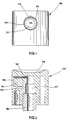
- FIG. 1 is a front view of the nozzle, then that the nozzle has been removed to reveal the interior of the nozzle.
- the push button 100 is in the form of a small cylinder closed at its upper end by a curved ergonomic surface 118 adapted to the application of a finger.
- the cylinder is made with a cylindrical housing 110 which is partially filled by a core 111 of shape cylindrical which extends horizontally to the center of the housing 110.
- An annular space 114 is thus created between the cylindrical internal wall of the housing 110 and the core 111.
- a window 112 communicates the annular space 114 with an internal channel 117, as can be see Figures 2 and 3.
- the internal channel 117 receives the end of a hollow rod actuation 103.
- the core 111 has a smooth front surface 119.
- a nozzle 102 is fitted with force on the core 111, as visible in FIG. 3.
- the nozzle 102 is presented under the shape of a small bucket whose bottom is pierced with an orifice 121, called spray.
- the sprinkler therefore comprises a bottom and an annular skirt 122 which is forcibly engaged in the annular space 114 (fig. 1).
- the internal wall of the skirt is made with three channels supply 113 distributed angularly and extending over the entire height of the skirt 122.
- the skirt does not come into contact with the bottom of the annular space 114 so that there is a annular passage 115 which communicates the window with the supply channels 113 (fig. 3).
- the bottom of the nozzle 102 has a structured internal wall 129 in which are formed three swirl channels 125 and a swirl 124 centered on the spray orifice 121 (fig. 4).
- the canals of swirl and the swirl chamber are completed by the waterproof application of the internal surface 129 of the nozzle against the smooth front surface 119 of the core. Canals are thus isolated from each other.
- the three channels of swirl 125 are each in communication with one of the three supply channels 113. The fluid distributed by the pump or the valve therefore flows through the rod hollow 103, the internal channel 117, the window 112, the annular passage 115, the three channels feed, the three swirl channels, the swirl chamber and the spray orifice.
- the height of the nozzle is directly related to the height of the nozzle, and therefore its structure.
- the present invention aims to reduce the height of the nozzle, which allows reduce the total height of the dispensing device.
- this problem is solved by providing advantageously that the swirl channels communicate with the outlet channel of the spraying device via several supply conduits symmetrical, to each of the swirl channels corresponding to a conduit feed, so that all of the swirl channels are supplied with product fluid evenly. This ensures that the fluid flow path is identical for each of the swirl channels.
- a reduction in height is possible, while ensuring a perfectly balanced supply of the swirl channels.
- a reduced size nozzle is produced, having in addition an improved dynamic behavior.
- the contact surface of the fluid on the nozzle is also reduced.
- the nozzle no longer needs to be fitted with as great a force as in the prior art.
- the nozzle must resist a pressure of 30.10 5 Pa, while for a nozzle according to the invention, a pressure of 12 to 15.10 5 Pa is sufficient. It is therefore simpler to hang a nozzle according to the invention, since the attachment means do not need to withstand high pressures.
- the spraying of the fluid product is obtained thanks to the vortex which is created in the swirl chamber, due to the fact that the swirl channels open out in the room non-radially.
- the fluid product therefore undergoes a movement vortex in the chamber which generates centrifugal acceleration before exiting at through the spray hole which is perfectly centered on the vortex eye.
- the product emitted fluid is then distributed in the atmosphere with a conical dispersion.
- the spray orifice is perfectly centered on the eye of the vortex, otherwise the fluid would be distributed with large droplets, because it is in the eye of the vortex that the acceleration is strongest.
- the nozzle must therefore be molded with great precision, so that the swirl chamber is exactly centered on the spray hole.
- the swirl channels must also be very precisely molded, as well as the feed channels. The sprinkler therefore constitutes a high precision part.
- the nozzle fitting on the core must also be performed with great precision.
- said swirl channels and at least part of the swirl chamber are formed in a front wall of the core, the nozzle having an inner wall in tight contact with said front wall of the core to isolate the channels from swirling from each other.
- the nozzle forms part of the chamber swirling.
- the swirl chamber therefore consists of two parts, one formed in the front wall of the core and the other in the nozzle.
- the part formed in the nozzle corresponds to that where the eye of the vortex is formed.
- the nozzle has a symmetry with respect to a plane extending perpendicular to the axis passing through the spray orifice, so that the nozzle has two identical faces thus making it reversible.
- the nozzle then simply presents itself in the form of an oblong patch pierced with a central hole formed between two recesses symmetrical cylinders which define the two parts of the swirl chamber.
- the nozzle does not include an annular skirt as is the case in the prior art. he therefore follows a considerable simplification of the nozzle which offers advantages to different levels.
- the nozzle is reversible due to its symmetry, which simplifies the orientation of the nozzle when it is mounted on the core.
- the sprinkler requires less of material due to its small size and the absence of an annular skirt.
- it is easier to mold with a mold in two identical parts.
- the chamber parts symmetrical with the centered spray hole are easier to achieve because the spindle required for molding is shorter, which increases its accuracy. So we can mold a nozzle according to the invention with great precision using a more spindle easy to manipulate.
- the nozzle is received hermetically in a housing containing the supply conduits and the core, said nozzle being provided on its periphery of contact with said housing of a sealing bead which bites into the constituent material said accommodation.
- the sprinkler is therefore forcibly engaged in the housing and is held there by a sort of harpoon effect.
- said nozzle has a peripheral penetration chamfer to facilitate mounting of said nozzle in said housing. During assembly, the nozzle does not need to be brought in perfectly centered towards the housing. If not, the penetration chamfers will refocus automatically the nozzle on its housing.
- the output channel of the spray has a crenellated free end which communicates with the conduits nozzle supply.
- the nozzle can be an integral part of a push button mounted on a rod hollow actuator defining the outlet channel.
- the push button is designated in this example by the numeric reference 1. It is intended to be fitted on an outlet channel such as a rod hollow actuation 3 of a fluid dispenser device such as a pump or a valve.
- the spray nozzle produced according to an embodiment of the invention is integrated into push-button 1, as is customary.
- the spray nozzle which will now be described in detail can just as easily be integrated in another element of a spraying device incorporating an outlet channel.
- the invention relates to the very structure of the nozzle and not to its arrangement with respect to the distribution device.
- the embodiment chosen to illustrate the invention puts however the spray nozzle used in a generally shaped push button classic.
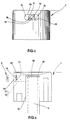
- Push button 1 is in the form of a small hollow cylinder closed at its upper end by a surface 18 adapted to receive pressure exerted by a finger for example.
- the push button 1 comprises on its cylindrical part an oblong housing 10 in which is received a nozzle of corresponding shape.
- Figures 5 and 6 show the push button with the nozzle removed to reveal the inside of the oblong housing 10.
- This contains a core 11 which partially fills said housing 10 and two conduits 12 and 13 so-called power supplies which sink into the push button on either side of the core extending parallel in a horizontal plane, when the surface 18 is directed towards the top, as shown in Figures 5 and 6. While conventionally, the core is surrounded by an annular passage (see 114, fig.
- the core no longer constitutes a protruding lug surrounded by an annular space, but is directly connected by its parts higher and lower than the constituent mass of the push button 1, as visible on the Figures 5 and 6.
- the core no longer projects freely towards the front, but literally part of the push button.
- the nucleus constitutes a partition wall for the two supply conduits 12, 13.
- the core 11 extends radially inward of the push button and ends just before it opens into the internal channel 17 in which the actuating rod 3 is mounted.
- the latter has an open upper end 30 which is produced with a notch whose tips are in abutment against the upper wall of the internal channel which defines also a part of the pushing surface 18. Thanks to this notch, the fluid product can flow out of the actuating rod 3 without the need to provide a any means at the top wall of the internal channel 17 to prevent the open upper end 30 of the rod 3 is not in tight contact with the wall upper of the internal channel 17, which would prevent the flow of the fluid product. We win thus in height since the actuating rod 3 penetrates as much as possible into the push button 1.
- the two supply ducts 12, 13 of the invention have much higher sections. Also, like the conduits supply connect the internal channel 17 without performing a throttling, there is no pressure drop at this level, whereas in a conventional nozzle of the prior art, the window 112 (fig. 1) was a cause of a large pressure drop just before the canals supply 113.
- the swirl channels can be supplied with fluid optimally without creating a pressure drop before their Entrance.
- the core 11 has a front end wall 19 which is slightly depressed in the housing 10 of about 1 millimeter.
- This wall 19 is not flat, but incorporates, a swirl chamber part 14 and two swirl channels 15 and 16 which open with one of their ends in the swirl chamber 14 of non-radial way and with the other of their ends respectively in each of supply ducts, as seen in Figure 5. While it is normally usual to mold the chamber and the swirl channels in the nozzle, according to the present invention, these are molded into the front wall of the core 11.
- the pin used in the mold adapted to mold such a nozzle is of a relatively simple design.
- this pin comprises two branches corresponding to the supply conduits 12 and 13 connected together by a bridge in which the negative of the chamber and channels of swirling is machined, for example by electro-erosion.
- the branches of the brooch extend into the internal channel 17 which is formed by another cylindrical pin the upper end of which is inserted between the two branches of the core pin.
- the core has a substantially trapezoidal shape to favor internal channel pin engagement and disengagement in and out respectively branches of the core pin.
- the branches of the core spindle engage in the internal channel 17.
- the part of the nozzle spraying which is an integral part of the push button is therefore very simple to carry out with only two extremely simple pins.
- the swirl channels being given that they each communicate with a supply duct, are perfectly symmetrical with respect to the swirl chamber and will therefore be supplied with fluid identically. This is a particularly advantageous characteristic, because it ensures perfect vortex formation in the vortex chamber.
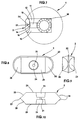
- the nozzle 2 corresponding to the shape of the housing 10 in which it is received, is oblong, in this case wider than high. As an example, the nozzle presents a width of about 3 millimeters for a height of about 1 millimeter. These magnitudes cannot be limiting. Compared to a conventional nozzle of the prior art, there is a gain almost 2 millimeters in height which affects the height of push button 1.
- the nozzle is in the form of an oblong grain pierced with a central orifice 21, called spray.
- the spray orifice is formed between two symmetrical recesses substantially cylindrical which it communicates and which each define a part of swirl chamber 24 complementary to the chamber part 14 formed in the core 11.
- the nozzle is symmetrical by with respect to a vertical plane perpendicular to the axis passing through the center of the orifice spraying and in which is contained the longitudinal axis of the nozzle.
- This plan therefore passes between the two parts of the swirl chamber 24, and thus makes the nozzle reversible, which explains the duplication of the complementary part 24 of the swirl. Only one of the complementary parts of room 24 will fulfill the function for which it is intended, the other then serving only as exhaust nozzle.
- This reversibility of the nozzle eliminates an operation prior orientation of the nozzle before mounting on the push button. This allows to eliminate a baffle in the bowl used for the orientation of the nozzle in the chain mounting.
- the technique preferably used is force engagement with material interference.
- the nozzle is provided on its outer oblong periphery of a sealing bead 22 which gives the nozzle a oversizing in relation to the housing 10.
- a material harder than that of the push button for example POM (polyoxymethylene) for the sprinkler and polyethylene for the push button
- cord 22 will bite into the internal wall of the housing by deformation of material.
- the nozzle is formed with penetration chamfers which allow to automatically center the nozzle on its housing.
- the nozzle is in contact by one of its faces 29, incorporating a part of swirl chamber 24, with the front wall 19 of the core incorporating the chamber 14 and the channels 15, 16.
- the contact between the face 29 and the front wall 19 is sealed, so that the swirl channels are isolated from each other others between the complete swirl chamber 14, 24 and the respective conduits supply 12, 13.
- the front wall 19 of the core extends vertically when the nozzle is straight outfit.
- the nozzle would be fitted obliquely, so that the spray would be sprayed with an angle of diffusion from the horizontal.
- the fluid tank must remain oriented vertically, while the product jet spray must be directed upwards with a predetermined diffusion angle.
- the swirl chamber which is traditionally formed only in the nozzle consists here of two parts respectively formed one in the core and the other in the sprinkler. This division into two parts does not cause any complications in terms of vortex formation in the vortex chamber, as it has been noticed that the eye of the vortex always forms in the center of the spray orifice, provided that the part of sprinkler chamber is well centered. In other words, the eye of the vortex is formed in the orifice even if the two chamber parts are not perfectly aligned. The precision during molding must therefore be carried on the nozzle. Now it is much easier to mold a flat nozzle (without annular skirt 122; fig. 3) which is moreover perfectly symmetrical.
- the necessary mold only consists of two identical parts each incorporating a spindle for forming the swirl chamber parts 24 and the spray orifice.
- the two pins required are extremely short and it is known that the precision of molding is all the greater the shorter the pins. Therefore, increased molding accuracy is achieved without using more pins precise.
- the nozzle is easily moldable with a minimum of material, using a very simple in two parts. It is also easy to mount on the push button due to its reversibility and the decrease in pressure on it.
Landscapes
- Chemical & Material Sciences (AREA)
- Dispersion Chemistry (AREA)
- Engineering & Computer Science (AREA)
- Mechanical Engineering (AREA)
- Nozzles (AREA)
Claims (11)
- Zerstäubungsdüse, die dazu dient, auf dem Ausgangskanal (3) eine Abgabevorrichtung für ein Fluid montiert zu werden, um dieses Fluid in feine Tröpfchen aufzuteilen, wobei die Düse einen Kern (11) und einen Zerstäuber (2) umfaßt, die hermetisch in einer Ausnehmung der Düse aufgenommen sind, wobei der Kern und der Zerstäuber gemeinsam folgendes definieren:dadurch gekennzeichnet, daß der Zerstäuber (2) und seine Ausnehmung eine längliche Form besitzen, deren große Längsachse sich in einer horizontalen Ebene erstreckt, wenn die Düse auf dem Ausgangskanal der Abgabevorrichtung montiert ist.eine Verwirbelungskammer (14, 24), die mit dem Außenbereich vermittels einer Zerstäuberöffnung (21) in Verbindung steht, die in dem Zerstäuber (2) ausgebildet ist, undmehrere Verwirbelungskanäle (15, 16), die in die Verwirbelungskammer (14, 24) in nicht radialer Weise münden,
- Zerstäubungsdüse nach Anspruch 1, bei der die Verwirbelungskanäle (15, 16) mit dem Ausgangskanal (3) der Zerstäubungsvorrichtung vermittels mehrerer symmetrischer Versorgungsleitungen (12, 13) in Verbindung stehen, wobei jeweils einer der Verwirbelungskanäle (15, 16) einer Versorgungsleitung (12, 13) entspricht, derart, daß alle Verwirbelungskanäle (15, 16) mit dem Fluid in gleicher Weise versorgt werden.
- Zerstäubungsdüse nach Anspruch 2, bei der zwei Versorgungsleitungen (12, 13) vorhanden sind und sich auf beiden Seiten des Kerns (11) in einer horizontalen Ebene erstrecken.
- Zerstäubungsdüse nach einem der Ansprüche 1 bis 3, dadurch gekennzeichnet, daß die Verwirbelungskanäle (15, 16) und wenigstens ein Teil (14) der Verwirbelungskammer in einer vorderen Wand (19) des Kerns (11) ausgebildet sind, wobei der Zerstäuber (2) eine Innenwand (29) besitzt, die in dichtem Kontakt mit der Vorderwand (19) des Kerns (11) steht, um die Verwirbelungskanäle (15, 16) voneinander zu isolieren.
- Zerstäubungsdüse nach einem der vorhergehenden Ansprüche, bei der der Zerstäuber (2) einen Teil (24) der Verwirbelungskammer bildet.
- Zerstäubungsdüse nach einem der vorhergehenden Ansprüche, bei der der Zerstäuber (2) bezüglich einer Ebene, die sich senkrecht zur Achse erstreckt, die durch die Zerstäubungsöffnung (21) verläuft, derart symmetrisch ausgebildet ist, daß der Zerstäuber zwei identische Flächen (29) aufweist, wodurch er umkehrbar ist.
- Zerstäubungsdüse nach einem der vorhergehenden Ansprüche, bei der der Zerstäuber (2) in hermetischer Weise in einer Ausnehmung (10) aufgenommen ist, welche die Versorgungsleitungen (12, 13) und den Kern (11) enthält, wobei der Zerstäuber (2) an seinem Berührungsumfang mit der Ausnehmung (10) mit einem Dichtrand versehen ist, der in das die Ausnehmung (10) bildende Material einschneidet.
- Zerstäubungsdüse nach Anspruch 7, bei der der Zerstäuber (2) eine umfangsmäßige Eindring-Abschrägung (28) aufweist, um die Montage des Zerstäubers (2) in der Ausnehmung (10) zu erleichtern.
- Zerstäubungsdüse nach einem der vorhergehenden Ansprüche, bei der der Ausgangskanal (3) der Zerstäubungsvorrichtung ein freies, mit Zacken versehenes Ende (30) besitzt, das mit den Versorgungsleitungen (12, 13) der Düse in Verbindung steht.
- Zerstäubungsdüse nach einem der vorhergehenden Ansprüche, bei der die Düse einen integralen Teil eines Drückers (1) bildet, der auf einer hohlen Betätigungsstange montiert ist, die den Ausgangskanal (3) definiert.
- Zerstäubungsdüse nach einem der vorhergehenden Ansprüche, bei der der Kern (11) eine Trennwand für die Versorgungsleitungen (12, 13) bildet.
Applications Claiming Priority (3)
| Application Number | Priority Date | Filing Date | Title |
|---|---|---|---|
| FR9500258 | 1995-01-11 | ||
| FR9500258A FR2729091B1 (fr) | 1995-01-11 | 1995-01-11 | Buse de pulverisation |
| PCT/FR1996/000028 WO1996021512A1 (fr) | 1995-01-11 | 1996-01-09 | Buse de pulverisation |
Publications (2)
| Publication Number | Publication Date |
|---|---|
| EP0802827A1 EP0802827A1 (de) | 1997-10-29 |
| EP0802827B1 true EP0802827B1 (de) | 1998-08-12 |
Family
ID=9475029
Family Applications (1)
| Application Number | Title | Priority Date | Filing Date |
|---|---|---|---|
| EP96901030A Expired - Lifetime EP0802827B1 (de) | 1995-01-11 | 1996-01-09 | Zerstäubungsdüse |
Country Status (6)
| Country | Link |
|---|---|
| US (1) | US5931386A (de) |
| EP (1) | EP0802827B1 (de) |
| DE (1) | DE69600521T2 (de) |
| ES (1) | ES2122780T3 (de) |
| FR (1) | FR2729091B1 (de) |
| WO (1) | WO1996021512A1 (de) |
Cited By (28)
| Publication number | Priority date | Publication date | Assignee | Title |
|---|---|---|---|---|
| USD492192S1 (en) | 2001-10-23 | 2004-06-29 | Medical Instill Technologies, Inc. | Dispenser |
| US6761286B2 (en) | 2000-10-23 | 2004-07-13 | Medical Instill Technologies, Inc. | Fluid dispenser having a housing and flexible inner bladder |
| USD495946S1 (en) | 2001-10-23 | 2004-09-14 | Medical Instill Technologies, Inc. | Dispenser |
| USD507680S1 (en) | 2004-01-27 | 2005-07-19 | Medical Instill Technologies, Inc. | Cosmetic applicator |
| USD507752S1 (en) | 2002-10-21 | 2005-07-26 | Medical Instill Technologies, Inc. | Dispenser |
| USD511975S1 (en) | 2004-09-27 | 2005-11-29 | Medical Instill Technologies, Inc. | Dispensing container |
| USD512646S1 (en) | 2004-01-27 | 2005-12-13 | Medical Instill Technologies, Inc. | Dispenser of a container |
| USD512647S1 (en) | 2004-01-27 | 2005-12-13 | Medical Instill Technologies, Inc. | Dispenser of a container |
| US6997219B2 (en) | 2003-05-12 | 2006-02-14 | Medical Instill Technologies, Inc. | Dispenser and apparatus and method for filling a dispenser |
| USD516251S1 (en) | 2003-09-29 | 2006-02-28 | Medical Instill Technologies, Inc. | Cosmetic applicator |
| USD516721S1 (en) | 2003-01-28 | 2006-03-07 | Medical Instill Technologies, Inc. | Dispenser |
| USD521639S1 (en) | 2003-11-14 | 2006-05-23 | Medical Instill Technologies, Inc. | Ophthalmic delivery device |
| USD521638S1 (en) | 2003-11-14 | 2006-05-23 | Medical Instill Technologies, Inc. | Ophthalmic delivery device |
| USD536138S1 (en) | 2004-01-27 | 2007-01-30 | Medical Instill, Technologies, Inc. | Cosmetic applicator |
| US7226231B2 (en) | 2003-07-17 | 2007-06-05 | Medical Instill Technologies, Inc. | Piston-type dispenser with one-way valve for storing and dispensing metered amounts of substances |
| USD548889S1 (en) | 2003-09-29 | 2007-08-14 | Medical Instill Technologies, Inc. | Cosmetic applicator |
| US7264142B2 (en) | 2004-01-27 | 2007-09-04 | Medical Instill Technologies, Inc. | Dispenser having variable-volume storage chamber and depressible one-way valve assembly for dispensing creams and other substances |
| USD552798S1 (en) | 2004-01-27 | 2007-10-09 | Medical Instill Technologies, Inc. | Cosmetic applicator |
| US7331944B2 (en) | 2000-10-23 | 2008-02-19 | Medical Instill Technologies, Inc. | Ophthalmic dispenser and associated method |
| USD570052S1 (en) | 2003-09-29 | 2008-05-27 | Medical Instill Technologies, Inc. | Cosmetic applicator |
| USD571224S1 (en) | 2004-09-27 | 2008-06-17 | Medical Instill Technologies, Inc. | Dispensing container |
| US7568509B2 (en) | 2003-04-28 | 2009-08-04 | Medical Instill Technologies, Inc. | Container with valve assembly, and apparatus and method for filling |
| US7810677B2 (en) | 2004-12-04 | 2010-10-12 | Medical Instill Technologies, Inc. | One-way valve and apparatus and method of using the valve |
| US7850051B2 (en) | 2004-12-04 | 2010-12-14 | Medical Instill Technologies, Inc. | Apparatus having one-way valve |
| US8348104B2 (en) | 2006-09-08 | 2013-01-08 | Medical Instill Technologies, Inc. | Apparatus for dispensing fluids |
| US8376189B2 (en) | 2010-05-07 | 2013-02-19 | Alps Llc | Dispensing machine valve and method |
| WO2013049867A1 (de) | 2011-10-05 | 2013-04-11 | Kurt Himmelfreundpointner | Verfahren und eine vorrichtung für die beeinflussung des geruches, welcher von schachtöffnungen von untertage verlaufenden abwasserkanälen ausgeht |
| US8672195B2 (en) | 2002-08-13 | 2014-03-18 | Medical Instill Technologies, Inc. | Device with chamber and first and second valves in communication therewith, and related method |
Families Citing this family (16)
| Publication number | Priority date | Publication date | Assignee | Title |
|---|---|---|---|---|
| FR2773851B1 (fr) * | 1998-01-20 | 2000-03-24 | Sagem | Injecteur de carburant pour moteur a combustion interne |
| IL133226A (en) * | 1999-11-30 | 2004-08-31 | Mamtirim Dan | Vortex liquid-atomizer |
| US6302101B1 (en) | 1999-12-14 | 2001-10-16 | Daniel Py | System and method for application of medicament into the nasal passage |
| US6685109B2 (en) * | 2001-09-24 | 2004-02-03 | Daniel Py | System and method for a two piece spray nozzle |
| US7798185B2 (en) | 2005-08-01 | 2010-09-21 | Medical Instill Technologies, Inc. | Dispenser and method for storing and dispensing sterile food product |
| US20050098177A1 (en) * | 2003-11-12 | 2005-05-12 | Sajed Haj-Yahya | Exhalation valve assembly |
| FR2885820B1 (fr) * | 2005-05-18 | 2007-06-22 | Rexam Dispensing Systems Sas | Buse a chambre tourbillonnaire |
| GB0515592D0 (en) | 2005-07-28 | 2005-09-07 | Glaxo Group Ltd | Nozzle for a nasal inhaler |
| USD543606S1 (en) * | 2005-11-07 | 2007-05-29 | Northern Tool & Equipment Company, Inc. | Broadcast spray nozzle |
| FR2902675B1 (fr) * | 2006-06-21 | 2008-09-12 | Lvmh Rech | Buse de distribution de produit de fluide et dispositif de distribution de produit de fluide comprenant une telle buse |
| GB2480856A (en) * | 2010-06-03 | 2011-12-07 | Norwich Pharma Technologies Ltd | A swirl imparting spray nozzle on a single-use dispensing canister |
| FR2961189B1 (fr) * | 2010-06-14 | 2013-02-22 | Valois Sas | Tete de distribution de produit fluide. |
| FR2971768B1 (fr) | 2011-02-18 | 2013-03-22 | Valois Sas | Tete de distribution de produit fluide. |
| US9981799B2 (en) | 2011-08-09 | 2018-05-29 | S.C. Johnson & Son, Inc. | Dispensing system |
| US8967436B2 (en) | 2011-08-09 | 2015-03-03 | S.C. Johnson & Son, Inc. | Dispensing system |
| DE102016114456A1 (de) * | 2016-08-04 | 2018-02-08 | Rpc Bramlage Gmbh | Fingerspraypumpe sowie Düsenkopf für eine Sprühpumpe |
Family Cites Families (11)
| Publication number | Priority date | Publication date | Assignee | Title |
|---|---|---|---|---|
| US3840157A (en) * | 1972-10-16 | 1974-10-08 | J Hellenkamp | Hand operated sprayer |
| US4036439A (en) * | 1975-09-24 | 1977-07-19 | Newman-Green, Inc. | Spray head for nebulization of fluids |
| US3990639A (en) * | 1976-01-19 | 1976-11-09 | Laauwe Robert H | Aerosol valve actuator |
| US4260110A (en) * | 1977-02-18 | 1981-04-07 | Winfried Werding | Spray nozzle, devices containing the same and apparatus for making such devices |
| US4182496A (en) * | 1977-12-16 | 1980-01-08 | Ethyl Products Company | Actuator button for fluid dispenser |
| FR2443879A1 (fr) * | 1978-12-13 | 1980-07-11 | Aerosol Inventions Dev | Dispositif a effet tourbillonnaire pour la pulverisation de liquides sous pression |
| DE3314020A1 (de) * | 1983-04-18 | 1984-10-18 | Hörauf & Kohler KG, 8900 Augsburg | Handbetaetigter fluessigkeitszerstaeuber |
| DE3443640A1 (de) * | 1984-11-29 | 1986-06-05 | Karlheinz 8902 Neusäß Kläger | Zerstaeuberduese eines fluessigkeitszerstaeubers |
| US5540389A (en) * | 1994-08-24 | 1996-07-30 | Aptar Group, Inc. | Terminal orifice system |
| US5711488A (en) * | 1995-10-13 | 1998-01-27 | The Procter & Gamble Company | High pressure swirl atomizer |
| US5738282A (en) * | 1996-03-20 | 1998-04-14 | Calmar Inc. | Pump sprayer nozzle for producing a solid spray pattern |
-
1995
- 1995-01-11 FR FR9500258A patent/FR2729091B1/fr not_active Expired - Fee Related
-
1996
- 1996-01-09 ES ES96901030T patent/ES2122780T3/es not_active Expired - Lifetime
- 1996-01-09 WO PCT/FR1996/000028 patent/WO1996021512A1/fr not_active Ceased
- 1996-01-09 DE DE69600521T patent/DE69600521T2/de not_active Expired - Lifetime
- 1996-01-09 EP EP96901030A patent/EP0802827B1/de not_active Expired - Lifetime
- 1996-01-09 US US08/860,202 patent/US5931386A/en not_active Expired - Fee Related
Cited By (58)
| Publication number | Priority date | Publication date | Assignee | Title |
|---|---|---|---|---|
| US7000806B2 (en) | 2000-10-23 | 2006-02-21 | Medical Instill Technologies, Inc. | Fluid dispenser having a housing and flexible inner bladder |
| US6761286B2 (en) | 2000-10-23 | 2004-07-13 | Medical Instill Technologies, Inc. | Fluid dispenser having a housing and flexible inner bladder |
| US9725228B2 (en) | 2000-10-23 | 2017-08-08 | Dr. Py Institute Llc | Fluid dispenser having a one-way valve, pump, variable-volume storage chamber, and a needle penetrable and laser resealable portion |
| US7331944B2 (en) | 2000-10-23 | 2008-02-19 | Medical Instill Technologies, Inc. | Ophthalmic dispenser and associated method |
| US8240521B2 (en) | 2000-10-23 | 2012-08-14 | Medical Instill Technologies, Inc. | Fluid dispenser having a one-way valve, pump, variable-volume storage chamber, and a needle penetrable and laser resealable portion |
| US8757436B2 (en) | 2000-10-23 | 2014-06-24 | Medical Instill Technologies, Inc. | Method for dispensing ophthalmic fluid |
| USD495946S1 (en) | 2001-10-23 | 2004-09-14 | Medical Instill Technologies, Inc. | Dispenser |
| USD503345S1 (en) | 2001-10-23 | 2005-03-29 | Medical Instill Technologies, Inc. | Pump for a dispenser |
| USD492192S1 (en) | 2001-10-23 | 2004-06-29 | Medical Instill Technologies, Inc. | Dispenser |
| US8672195B2 (en) | 2002-08-13 | 2014-03-18 | Medical Instill Technologies, Inc. | Device with chamber and first and second valves in communication therewith, and related method |
| US9408455B2 (en) | 2002-08-13 | 2016-08-09 | MedInstill Development, LLC | Container and valve assembly for storing and dispensing substances, and related method |
| USD507752S1 (en) | 2002-10-21 | 2005-07-26 | Medical Instill Technologies, Inc. | Dispenser |
| USD516721S1 (en) | 2003-01-28 | 2006-03-07 | Medical Instill Technologies, Inc. | Dispenser |
| US8272411B2 (en) | 2003-04-28 | 2012-09-25 | Medical Instill Technologies, Inc. | Lyophilization method and device |
| US7568509B2 (en) | 2003-04-28 | 2009-08-04 | Medical Instill Technologies, Inc. | Container with valve assembly, and apparatus and method for filling |
| US6997219B2 (en) | 2003-05-12 | 2006-02-14 | Medical Instill Technologies, Inc. | Dispenser and apparatus and method for filling a dispenser |
| US7328729B2 (en) | 2003-05-12 | 2008-02-12 | Medical Instill Technologies, Inc. | Dispenser and apparatus and method for filling a dispenser |
| US7861750B2 (en) | 2003-05-12 | 2011-01-04 | Medical Instill Technologies, Inc. | Dispenser and apparatus and method of filling a dispenser |
| US8240934B2 (en) | 2003-07-17 | 2012-08-14 | Medical Instill Technologies, Inc. | Dispenser with one-way valve for storing and dispensing substances |
| US7226231B2 (en) | 2003-07-17 | 2007-06-05 | Medical Instill Technologies, Inc. | Piston-type dispenser with one-way valve for storing and dispensing metered amounts of substances |
| US9440773B2 (en) | 2003-07-17 | 2016-09-13 | Medinstill Development Llc | Device with one-way valve |
| US7651291B2 (en) | 2003-07-17 | 2010-01-26 | Medical Instill Technologies, Inc. | Dispenser with one-way valve for storing and dispensing metered amounts of substances |
| USD516251S1 (en) | 2003-09-29 | 2006-02-28 | Medical Instill Technologies, Inc. | Cosmetic applicator |
| USD530862S1 (en) | 2003-09-29 | 2006-10-24 | Medical Instill Technologies, Inc. | Cosmetic applicator |
| USD570052S1 (en) | 2003-09-29 | 2008-05-27 | Medical Instill Technologies, Inc. | Cosmetic applicator |
| USD548889S1 (en) | 2003-09-29 | 2007-08-14 | Medical Instill Technologies, Inc. | Cosmetic applicator |
| USD521639S1 (en) | 2003-11-14 | 2006-05-23 | Medical Instill Technologies, Inc. | Ophthalmic delivery device |
| USD555791S1 (en) | 2003-11-14 | 2007-11-20 | Medical Instill Technologies, Inc. | Ophthalmic delivery device |
| USD555784S1 (en) | 2003-11-14 | 2007-11-20 | Medical Instill Technologies, Inc. | Ophthalmic delivery device |
| USD521638S1 (en) | 2003-11-14 | 2006-05-23 | Medical Instill Technologies, Inc. | Ophthalmic delivery device |
| USD586904S1 (en) | 2003-11-14 | 2009-02-17 | Medical Instill Technologies, Inc. | Ophthalmic delivery device |
| USD587377S1 (en) | 2003-11-14 | 2009-02-24 | Medical Instill Technologies, Inc. | Ophthalmic delivery device |
| USD536138S1 (en) | 2004-01-27 | 2007-01-30 | Medical Instill, Technologies, Inc. | Cosmetic applicator |
| USD577605S1 (en) | 2004-01-27 | 2008-09-30 | Medical Instill Technologies, Inc. | Tubular container |
| USD573034S1 (en) | 2004-01-27 | 2008-07-15 | Medical Instill Technologies, Inc. | Dispensing container |
| USD512646S1 (en) | 2004-01-27 | 2005-12-13 | Medical Instill Technologies, Inc. | Dispenser of a container |
| US7644842B2 (en) | 2004-01-27 | 2010-01-12 | Medical Instill Technologies, Inc. | Dispenser having variable-volume storage chamber and depressible one-way valve assembly for dispensing creams and other substances |
| USD555508S1 (en) | 2004-01-27 | 2007-11-20 | Medical Instill Technologies, Inc. | Dispenser of a container |
| USD507680S1 (en) | 2004-01-27 | 2005-07-19 | Medical Instill Technologies, Inc. | Cosmetic applicator |
| USD512647S1 (en) | 2004-01-27 | 2005-12-13 | Medical Instill Technologies, Inc. | Dispenser of a container |
| USD523179S1 (en) | 2004-01-27 | 2006-06-13 | Medical Instill Technologies, Inc. | Cosmetic applicator |
| US7264142B2 (en) | 2004-01-27 | 2007-09-04 | Medical Instill Technologies, Inc. | Dispenser having variable-volume storage chamber and depressible one-way valve assembly for dispensing creams and other substances |
| USD554525S1 (en) | 2004-01-27 | 2007-11-06 | Medical Instill Technologies, Inc. | Dispensing container |
| USD554524S1 (en) | 2004-01-27 | 2007-11-06 | Medical Instill Technologies, Inc. | Dispensing container |
| USD552798S1 (en) | 2004-01-27 | 2007-10-09 | Medical Instill Technologies, Inc. | Cosmetic applicator |
| USD511975S1 (en) | 2004-09-27 | 2005-11-29 | Medical Instill Technologies, Inc. | Dispensing container |
| USD571224S1 (en) | 2004-09-27 | 2008-06-17 | Medical Instill Technologies, Inc. | Dispensing container |
| US7850051B2 (en) | 2004-12-04 | 2010-12-14 | Medical Instill Technologies, Inc. | Apparatus having one-way valve |
| US8602259B2 (en) | 2004-12-04 | 2013-12-10 | Medical Instill Technologies, Inc. | One-way valve and apparatus and method of using the valve |
| US8104644B2 (en) | 2004-12-04 | 2012-01-31 | Medical Instill Technologies, Inc. | One-way valve and apparatus and method of using the valve |
| US7810677B2 (en) | 2004-12-04 | 2010-10-12 | Medical Instill Technologies, Inc. | One-way valve and apparatus and method of using the valve |
| US8550308B2 (en) | 2006-09-08 | 2013-10-08 | Medical Instill Technologies, Inc. | Apparatus for dispensing fluids |
| US8356733B2 (en) | 2006-09-08 | 2013-01-22 | Medical Instill Technologies, Inc. | Method for dispensing fluids |
| US8348104B2 (en) | 2006-09-08 | 2013-01-08 | Medical Instill Technologies, Inc. | Apparatus for dispensing fluids |
| US8376189B2 (en) | 2010-05-07 | 2013-02-19 | Alps Llc | Dispensing machine valve and method |
| US8910833B2 (en) | 2010-05-07 | 2014-12-16 | Alps, Llc | Dispensing machine valve and method |
| US9423041B2 (en) | 2010-05-07 | 2016-08-23 | Alps Llc | Dispensing machine valve and method |
| WO2013049867A1 (de) | 2011-10-05 | 2013-04-11 | Kurt Himmelfreundpointner | Verfahren und eine vorrichtung für die beeinflussung des geruches, welcher von schachtöffnungen von untertage verlaufenden abwasserkanälen ausgeht |
Also Published As
| Publication number | Publication date |
|---|---|
| WO1996021512A1 (fr) | 1996-07-18 |
| DE69600521D1 (de) | 1998-09-17 |
| ES2122780T3 (es) | 1998-12-16 |
| FR2729091A1 (fr) | 1996-07-12 |
| DE69600521T2 (de) | 1999-05-06 |
| US5931386A (en) | 1999-08-03 |
| EP0802827A1 (de) | 1997-10-29 |
| FR2729091B1 (fr) | 1997-05-30 |
Similar Documents
| Publication | Publication Date | Title |
|---|---|---|
| EP0802827B1 (de) | Zerstäubungsdüse | |
| EP2475463B1 (de) | Vorrichtung zur ausgabe einer flüssigkeit | |
| EP1697670B1 (de) | Fluidproduktsprühkopf und diesen sprühkopf umfassende abgabepumpe | |
| EP3231516B1 (de) | Spritzdüse, insbesondere für ein system zur verteilung eines unter druck stehenden produkts, das mit einem druckknopf ausgestattet ist, und verteilungssystem, das eine solche düse umfasst | |
| EP0705143A1 (de) | Sprühdüse und zerstauber mit einer solchen düse | |
| EP0437131A1 (de) | Vordruck-Handpumpe zum zerstäuben einer Flüssigkeit, insbesondere eines Parfüms | |
| EP2258484B1 (de) | Druckknopf für eine Vorrichtung zur Abgabe einer unter Druck Flüssigkeit | |
| EP2606980B1 (de) | Druckknopf für ein Verteilungssystem eines unter Druck stehenden Produkts | |
| EP1054820A1 (de) | Pumpen-ausgabekopf oder ventil-ausgabekopf | |
| EP2119508B1 (de) | Druckknopf mit konvergierenden Verteilungskanälen | |
| FR3130652A1 (fr) | Tête de pulvérisation | |
| WO2004013017A1 (fr) | Dispositif de pulverisation de produit fluide | |
| EP2233211B1 (de) | Druckknopf für einen spender zum Spenden von flüssigkeiten unter Druck | |
| EP1677916B1 (de) | Spritzkopf für flüssiges produkt | |
| EP2590753A1 (de) | Sprühkopf für eine vorrichtung zur ausgabe eines flüssigprodukts | |
| EP1670699B1 (de) | Sprühkopf für fliessfähige medien und verfahren zum herstellen eines derartigen kopfes | |
| EP2353726B1 (de) | Druckknopf für ein Verteilungssystem eines unter Druck stehenden Produkts | |
| EP3615224B1 (de) | Kopfteil für die ausgabe eines flüssigprodukts | |
| EP1230031B1 (de) | Pumpe mit schneller hin- und herbewegung | |
| FR3083724A1 (fr) | Dispositif de distribution d'une pluralite de produits cosmetiques | |
| FR2881722A1 (fr) | Tete de distribution de produit fluide. | |
| FR2851483A1 (fr) | Tete de distribution | |
| FR2855159A1 (fr) | Tete de distribution montee ou faisant partie d'un organe de distribution de produit fluide | |
| FR2857340A1 (fr) | Organe de distribution de produit fluide et distributeur comprenant un tel organe |
Legal Events
| Date | Code | Title | Description |
|---|---|---|---|
| PUAI | Public reference made under article 153(3) epc to a published international application that has entered the european phase |
Free format text: ORIGINAL CODE: 0009012 |
|
| 17P | Request for examination filed |
Effective date: 19970808 |
|
| AK | Designated contracting states |
Kind code of ref document: A1 Designated state(s): DE ES FR GB IT |
|
| GRAG | Despatch of communication of intention to grant |
Free format text: ORIGINAL CODE: EPIDOS AGRA |
|
| GRAG | Despatch of communication of intention to grant |
Free format text: ORIGINAL CODE: EPIDOS AGRA |
|
| GRAH | Despatch of communication of intention to grant a patent |
Free format text: ORIGINAL CODE: EPIDOS IGRA |
|
| 17Q | First examination report despatched |
Effective date: 19980128 |
|
| GRAH | Despatch of communication of intention to grant a patent |
Free format text: ORIGINAL CODE: EPIDOS IGRA |
|
| GRAA | (expected) grant |
Free format text: ORIGINAL CODE: 0009210 |
|
| AK | Designated contracting states |
Kind code of ref document: B1 Designated state(s): DE ES FR GB IT |
|
| REF | Corresponds to: |
Ref document number: 69600521 Country of ref document: DE Date of ref document: 19980917 |
|
| GBT | Gb: translation of ep patent filed (gb section 77(6)(a)/1977) |
Effective date: 19981006 |
|
| REG | Reference to a national code |
Ref country code: ES Ref legal event code: FG2A Ref document number: 2122780 Country of ref document: ES Kind code of ref document: T3 |
|
| PLBE | No opposition filed within time limit |
Free format text: ORIGINAL CODE: 0009261 |
|
| STAA | Information on the status of an ep patent application or granted ep patent |
Free format text: STATUS: NO OPPOSITION FILED WITHIN TIME LIMIT |
|
| 26N | No opposition filed | ||
| REG | Reference to a national code |
Ref country code: GB Ref legal event code: IF02 |
|
| REG | Reference to a national code |
Ref country code: FR Ref legal event code: CD Owner name: APTAR FRANCE SAS, FR Effective date: 20130104 |
|
| REG | Reference to a national code |
Ref country code: DE Ref legal event code: R082 Ref document number: 69600521 Country of ref document: DE Representative=s name: BITTNER & PARTNER, DE |
|
| REG | Reference to a national code |
Ref country code: DE Ref legal event code: R082 Ref document number: 69600521 Country of ref document: DE Representative=s name: STAUDT IP LAW, DE Effective date: 20130802 Ref country code: DE Ref legal event code: R082 Ref document number: 69600521 Country of ref document: DE Representative=s name: BITTNER & PARTNER RECHTS- UND PATENTANWAELTE, DE Effective date: 20130802 Ref country code: DE Ref legal event code: R082 Ref document number: 69600521 Country of ref document: DE Representative=s name: BITTNER & PARTNER, DE Effective date: 20130802 Ref country code: DE Ref legal event code: R081 Ref document number: 69600521 Country of ref document: DE Owner name: APTAR FRANCE SAS, FR Free format text: FORMER OWNER: VALOIS S.A., LE NEUBOURG, FR Effective date: 20130802 |
|
| REG | Reference to a national code |
Ref country code: ES Ref legal event code: PC2A Owner name: APTAR FRANCE S.A.S. Effective date: 20141029 |
|
| REG | Reference to a national code |
Ref country code: ES Ref legal event code: PC2A Owner name: APTAR FRANCE SAS Effective date: 20141121 |
|
| REG | Reference to a national code |
Ref country code: FR Ref legal event code: PLFP Year of fee payment: 20 |
|
| PGFP | Annual fee paid to national office [announced via postgrant information from national office to epo] |
Ref country code: IT Payment date: 20150115 Year of fee payment: 20 Ref country code: DE Payment date: 20150109 Year of fee payment: 20 Ref country code: ES Payment date: 20150126 Year of fee payment: 20 |
|
| PGFP | Annual fee paid to national office [announced via postgrant information from national office to epo] |
Ref country code: GB Payment date: 20150114 Year of fee payment: 20 Ref country code: FR Payment date: 20150128 Year of fee payment: 20 |
|
| REG | Reference to a national code |
Ref country code: DE Ref legal event code: R082 Ref document number: 69600521 Country of ref document: DE Representative=s name: STAUDT IP LAW, DE |
|
| REG | Reference to a national code |
Ref country code: DE Ref legal event code: R071 Ref document number: 69600521 Country of ref document: DE |
|
| REG | Reference to a national code |
Ref country code: GB Ref legal event code: PE20 Expiry date: 20160108 |
|
| REG | Reference to a national code |
Ref country code: ES Ref legal event code: FD2A Effective date: 20160426 |
|
| PG25 | Lapsed in a contracting state [announced via postgrant information from national office to epo] |
Ref country code: GB Free format text: LAPSE BECAUSE OF EXPIRATION OF PROTECTION Effective date: 20160108 |
|
| PG25 | Lapsed in a contracting state [announced via postgrant information from national office to epo] |
Ref country code: ES Free format text: LAPSE BECAUSE OF EXPIRATION OF PROTECTION Effective date: 20160110 |