EP0802811B1 - Injektionsvorrichtung - Google Patents
Injektionsvorrichtung Download PDFInfo
- Publication number
- EP0802811B1 EP0802811B1 EP95935794A EP95935794A EP0802811B1 EP 0802811 B1 EP0802811 B1 EP 0802811B1 EP 95935794 A EP95935794 A EP 95935794A EP 95935794 A EP95935794 A EP 95935794A EP 0802811 B1 EP0802811 B1 EP 0802811B1
- Authority
- EP
- European Patent Office
- Prior art keywords
- drive member
- transmission
- injection device
- plunger
- sleeve
- Prior art date
- Legal status (The legal status is an assumption and is not a legal conclusion. Google has not performed a legal analysis and makes no representation as to the accuracy of the status listed.)
- Expired - Lifetime
Links
- 238000002347 injection Methods 0.000 title claims abstract description 45
- 239000007924 injection Substances 0.000 title claims abstract description 45
- 230000005540 biological transmission Effects 0.000 claims description 44
- 239000007788 liquid Substances 0.000 claims description 26
- 230000006835 compression Effects 0.000 claims description 7
- 238000007906 compression Methods 0.000 claims description 7
- 239000003708 ampul Substances 0.000 claims description 6
- 238000006073 displacement reaction Methods 0.000 claims description 6
- 230000003287 optical effect Effects 0.000 claims description 2
- 238000004519 manufacturing process Methods 0.000 abstract description 5
- 230000007704 transition Effects 0.000 description 3
- 239000011324 bead Substances 0.000 description 1
- 230000001419 dependent effect Effects 0.000 description 1
- 238000011161 development Methods 0.000 description 1
- 230000018109 developmental process Effects 0.000 description 1
- 239000003814 drug Substances 0.000 description 1
- 229940079593 drug Drugs 0.000 description 1
- 230000000694 effects Effects 0.000 description 1
- 239000012530 fluid Substances 0.000 description 1
- 238000000034 method Methods 0.000 description 1
- 238000003825 pressing Methods 0.000 description 1
- 239000000243 solution Substances 0.000 description 1
- 239000007921 spray Substances 0.000 description 1
- 238000003860 storage Methods 0.000 description 1
Images

Classifications
-
- A—HUMAN NECESSITIES
- A61—MEDICAL OR VETERINARY SCIENCE; HYGIENE
- A61M—DEVICES FOR INTRODUCING MEDIA INTO, OR ONTO, THE BODY; DEVICES FOR TRANSDUCING BODY MEDIA OR FOR TAKING MEDIA FROM THE BODY; DEVICES FOR PRODUCING OR ENDING SLEEP OR STUPOR
- A61M5/00—Devices for bringing media into the body in a subcutaneous, intra-vascular or intramuscular way; Accessories therefor, e.g. filling or cleaning devices, arm-rests
- A61M5/178—Syringes
- A61M5/31—Details
- A61M5/315—Pistons; Piston-rods; Guiding, blocking or restricting the movement of the rod or piston; Appliances on the rod for facilitating dosing ; Dosing mechanisms
- A61M5/31565—Administration mechanisms, i.e. constructional features, modes of administering a dose
- A61M5/3159—Dose expelling manners
- A61M5/31593—Multi-dose, i.e. individually set dose repeatedly administered from the same medicament reservoir
-
- A—HUMAN NECESSITIES
- A61—MEDICAL OR VETERINARY SCIENCE; HYGIENE
- A61M—DEVICES FOR INTRODUCING MEDIA INTO, OR ONTO, THE BODY; DEVICES FOR TRANSDUCING BODY MEDIA OR FOR TAKING MEDIA FROM THE BODY; DEVICES FOR PRODUCING OR ENDING SLEEP OR STUPOR
- A61M5/00—Devices for bringing media into the body in a subcutaneous, intra-vascular or intramuscular way; Accessories therefor, e.g. filling or cleaning devices, arm-rests
- A61M5/178—Syringes
- A61M5/31—Details
- A61M5/315—Pistons; Piston-rods; Guiding, blocking or restricting the movement of the rod or piston; Appliances on the rod for facilitating dosing ; Dosing mechanisms
- A61M5/31533—Dosing mechanisms, i.e. setting a dose
- A61M5/31545—Setting modes for dosing
- A61M5/31548—Mechanically operated dose setting member
- A61M5/3155—Mechanically operated dose setting member by rotational movement of dose setting member, e.g. during setting or filling of a syringe
- A61M5/31553—Mechanically operated dose setting member by rotational movement of dose setting member, e.g. during setting or filling of a syringe without axial movement of dose setting member
-
- A—HUMAN NECESSITIES
- A61—MEDICAL OR VETERINARY SCIENCE; HYGIENE
- A61M—DEVICES FOR INTRODUCING MEDIA INTO, OR ONTO, THE BODY; DEVICES FOR TRANSDUCING BODY MEDIA OR FOR TAKING MEDIA FROM THE BODY; DEVICES FOR PRODUCING OR ENDING SLEEP OR STUPOR
- A61M5/00—Devices for bringing media into the body in a subcutaneous, intra-vascular or intramuscular way; Accessories therefor, e.g. filling or cleaning devices, arm-rests
- A61M5/178—Syringes
- A61M5/31—Details
- A61M5/315—Pistons; Piston-rods; Guiding, blocking or restricting the movement of the rod or piston; Appliances on the rod for facilitating dosing ; Dosing mechanisms
- A61M5/31533—Dosing mechanisms, i.e. setting a dose
- A61M5/31545—Setting modes for dosing
- A61M5/31548—Mechanically operated dose setting member
- A61M5/31556—Accuracy improving means
-
- A—HUMAN NECESSITIES
- A61—MEDICAL OR VETERINARY SCIENCE; HYGIENE
- A61M—DEVICES FOR INTRODUCING MEDIA INTO, OR ONTO, THE BODY; DEVICES FOR TRANSDUCING BODY MEDIA OR FOR TAKING MEDIA FROM THE BODY; DEVICES FOR PRODUCING OR ENDING SLEEP OR STUPOR
- A61M5/00—Devices for bringing media into the body in a subcutaneous, intra-vascular or intramuscular way; Accessories therefor, e.g. filling or cleaning devices, arm-rests
- A61M5/178—Syringes
- A61M5/31—Details
- A61M5/315—Pistons; Piston-rods; Guiding, blocking or restricting the movement of the rod or piston; Appliances on the rod for facilitating dosing ; Dosing mechanisms
- A61M5/31565—Administration mechanisms, i.e. constructional features, modes of administering a dose
- A61M5/31566—Means improving security or handling thereof
- A61M5/31571—Means preventing accidental administration
-
- A—HUMAN NECESSITIES
- A61—MEDICAL OR VETERINARY SCIENCE; HYGIENE
- A61M—DEVICES FOR INTRODUCING MEDIA INTO, OR ONTO, THE BODY; DEVICES FOR TRANSDUCING BODY MEDIA OR FOR TAKING MEDIA FROM THE BODY; DEVICES FOR PRODUCING OR ENDING SLEEP OR STUPOR
- A61M5/00—Devices for bringing media into the body in a subcutaneous, intra-vascular or intramuscular way; Accessories therefor, e.g. filling or cleaning devices, arm-rests
- A61M5/178—Syringes
- A61M5/31—Details
- A61M5/315—Pistons; Piston-rods; Guiding, blocking or restricting the movement of the rod or piston; Appliances on the rod for facilitating dosing ; Dosing mechanisms
- A61M5/31565—Administration mechanisms, i.e. constructional features, modes of administering a dose
- A61M5/31576—Constructional features or modes of drive mechanisms for piston rods
- A61M5/31578—Constructional features or modes of drive mechanisms for piston rods based on axial translation, i.e. components directly operatively associated and axially moved with plunger rod
- A61M5/3158—Constructional features or modes of drive mechanisms for piston rods based on axial translation, i.e. components directly operatively associated and axially moved with plunger rod performed by axially moving actuator operated by user, e.g. an injection button
-
- A—HUMAN NECESSITIES
- A61—MEDICAL OR VETERINARY SCIENCE; HYGIENE
- A61M—DEVICES FOR INTRODUCING MEDIA INTO, OR ONTO, THE BODY; DEVICES FOR TRANSDUCING BODY MEDIA OR FOR TAKING MEDIA FROM THE BODY; DEVICES FOR PRODUCING OR ENDING SLEEP OR STUPOR
- A61M5/00—Devices for bringing media into the body in a subcutaneous, intra-vascular or intramuscular way; Accessories therefor, e.g. filling or cleaning devices, arm-rests
- A61M5/178—Syringes
- A61M5/24—Ampoule syringes, i.e. syringes with needle for use in combination with replaceable ampoules or carpules, e.g. automatic
-
- A—HUMAN NECESSITIES
- A61—MEDICAL OR VETERINARY SCIENCE; HYGIENE
- A61M—DEVICES FOR INTRODUCING MEDIA INTO, OR ONTO, THE BODY; DEVICES FOR TRANSDUCING BODY MEDIA OR FOR TAKING MEDIA FROM THE BODY; DEVICES FOR PRODUCING OR ENDING SLEEP OR STUPOR
- A61M5/00—Devices for bringing media into the body in a subcutaneous, intra-vascular or intramuscular way; Accessories therefor, e.g. filling or cleaning devices, arm-rests
- A61M5/178—Syringes
- A61M5/31—Details
- A61M5/315—Pistons; Piston-rods; Guiding, blocking or restricting the movement of the rod or piston; Appliances on the rod for facilitating dosing ; Dosing mechanisms
- A61M5/31533—Dosing mechanisms, i.e. setting a dose
- A61M5/31535—Means improving security or handling thereof, e.g. blocking means, means preventing insufficient dosing, means allowing correction of overset dose
-
- A—HUMAN NECESSITIES
- A61—MEDICAL OR VETERINARY SCIENCE; HYGIENE
- A61M—DEVICES FOR INTRODUCING MEDIA INTO, OR ONTO, THE BODY; DEVICES FOR TRANSDUCING BODY MEDIA OR FOR TAKING MEDIA FROM THE BODY; DEVICES FOR PRODUCING OR ENDING SLEEP OR STUPOR
- A61M5/00—Devices for bringing media into the body in a subcutaneous, intra-vascular or intramuscular way; Accessories therefor, e.g. filling or cleaning devices, arm-rests
- A61M5/178—Syringes
- A61M5/31—Details
- A61M5/315—Pistons; Piston-rods; Guiding, blocking or restricting the movement of the rod or piston; Appliances on the rod for facilitating dosing ; Dosing mechanisms
- A61M5/31533—Dosing mechanisms, i.e. setting a dose
- A61M5/31545—Setting modes for dosing
- A61M5/31548—Mechanically operated dose setting member
- A61M5/31561—Mechanically operated dose setting member using freely adjustable volume steps
Definitions
- the invention relates to a device for repeated injection of doses of a liquid drug according to the preamble of claim 1.
- the gear is not locked in all three positions, so that it is during storage or transportation of the injection device Can be subject to influences that change the Amount of liquid in the carpule or even to enter Air can lead into the carpule. It also owns many components, some of which are not easy to manufacture are.
- the invention has for its object a To create injection device in at least one Position, which is then considered the end position, automatically can be locked.
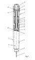
- the injection device shown in Figures 1 to 3 has a carpule part 1 and a gear 2, which in are easy to assemble and separate, for example with a thread or a bayonet catch.
- the carpule part 2 contains a liquid container 3, in called the "carpule" 3, the one with the one to be injected Liquid is filled, a cartridge holder 4, a piston 5, which always rests on the liquid and which when injected displaced liquid to be injected, a needle holder 6 and a needle 7 from which the liquid to be injected emerges.
- the gear 2 After the end of each injection, the gear 2 is in each case in a locked end position (Fig. 1), it can in the end position (Fig. 1) also stored and transported become.
- this end position (Fig. 1) is the drive member 12, 13 compared to the gear sleeve 8 so far in the Advance direction in the direction of the piston 5, that the lock 16, 17, 20, 21 between the gear sleeve 8 and the drive member 12, 13 engages and this against Secures rotation and longitudinal displacement.
- the lock 16, 17, 20, 21 consists for example of a locking ring 16 comprising the drive member 12, 13 and an associated cam 20. This sits in the Gear case 8 and engages, pressed by a spring 17, in the end position (Fig. 1) in the drive member 12, 13. The The cam can only come out of the groove 21 by pressing against the spring 17 be released on the locking ring 16. Is the Lock 16, 17, 20, 21 released, so is the drive member 12, 13 rotatable and displaceable again and is by the Compression spring 14 automatically in the later described Rest position (Fig. 2) shifted.
- a lock that has comparable properties, but can also apply to others To be built wisely.
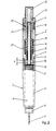
- the gearbox 2 To carry out a new injection, the gearbox 2 first brought into a rest position (Fig. 2). In this is the drive member 12, 13 against the feed direction of the Piston 5 pushed as far away from this as possible by what Compression spring 14 happens, the distance H up to one pushes second stop 19 on the transmission sleeve 8.
- the second Stop 19 is, for example, an annular bead on the Inner jacket surface of the gear sleeve 8.
- the gear element 11 is still in the direction of the piston 5 at the first stop 18 of the transmission sleeve 8. The transition from the end position (Fig. 1) in the rest position (Fig.
- the transmission 2 is brought into an intermediate position (FIG. 3), by which the amount of liquid to be injected during the next injection is predetermined.
- the gearbox is in the end position (Fig. 1) brought.
- the injection process runs from.
- the drive member 12, 13 by the path length H in the The direction of advance of the piston 5 is advanced.
- the drive link 12, 13 takes the distance X from the first when advancing Stop 18 on the gear sleeve 8 standing gear element 11 forward with.
- the gear element 11 takes that only longitudinally displaceable output member 9, 10 over the path length X With.
- the cartridge 3 After consumption of all the liquid the cartridge 3 will in the rest position (Fig. 2) of the carpule part 1 of the Transmission 2 separated. Then by turning the Drive member 12,13 in the opposite direction of rotation as in the transition from the rest position (Fig. 2) to the intermediate position (Fig. 3) the output member 9, 10 are reset until the Flange 10 on a through the piston 5 facing End of the transmission sleeve 8 formed deflection 23 strikes.
- new cartridges 3 are so filled that the piston 5 when installed in the Injection device through the flange 10 a little is pushed forward and some liquid from the needle 7 exit. This ensures that even at the first Injection with the new carpule 3 no air is injected.
- Injection devices according to the invention can be known Wise electrical, optical or acoustic devices have, with which the set path length X can be displayed. This can be a ratchet, for example, between the Drive member 9, 10 and the transmission sleeve 8 acts.
- the injection device according to the invention has a Lock 16, 17, 20, 21, which prevents in the End position (Fig. 1) also with unwanted operations can be made to her. This means that they are with attached carpule 3 stored and transported more reliably can be considered as the prior art devices. In addition, their structure is less and partially in Components that can be produced in a simple manner are required than for this, so that it requires less manufacturing costs.
Landscapes
- Health & Medical Sciences (AREA)
- Vascular Medicine (AREA)
- Engineering & Computer Science (AREA)
- Anesthesiology (AREA)
- Biomedical Technology (AREA)
- Heart & Thoracic Surgery (AREA)
- Hematology (AREA)
- Life Sciences & Earth Sciences (AREA)
- Animal Behavior & Ethology (AREA)
- General Health & Medical Sciences (AREA)
- Public Health (AREA)
- Veterinary Medicine (AREA)
- Infusion, Injection, And Reservoir Apparatuses (AREA)
- Chemical Or Physical Treatment Of Fibers (AREA)
- Polarising Elements (AREA)
- Injection Moulding Of Plastics Or The Like (AREA)
Description
- ein aus einem Führungsknopf und eine fest mit ihm verbundene Mitnehmerhülse bestehendes Antriebsglied, das drehbar und in der Vorschubrichtung des Kolbens hin- und herverschieblich in der Getriebehülse angebracht ist,
- ein in der Vorschubrichtung des Kolbens verschiebbares, aus einer Gewindestange und einem Flansch bestehendes Abtriebsglied, das von dem Antriebsglied bei Längsverschiebungen streckenweise mitnehmbar ist,
- ein Getriebeelement, das an der Gewindestange schraubbar gelagert ist, und
- eine Druckfeder, die zwischen dem Getriebeelement und der Mitnehmerhülse wirkt.
- eine Ruhestellung, in der das Antriebsglied weitmöglichst vom Kolben entfernt ist und das Getriebeelement nahe am Kolben liegt,
- eine Zwischenstellung, in der das Antriebsglied in seiner Stellung bleibt, bei der jedoch das Getriebeelement in einer von der zu injizierenden Flüssigkeitsmenge abhängigen Weise weiter vom Kolben entfernt liegt als bei der Ruhestellung und
- eine Endstellung, in der das Antriebsglied näher am Kolben
liegt und das Abtriebsglied weiter als in der Ruhe- und der
Zwischenstellung aus dem Getriebe herausgefahren und in die
Karpule eingedrungen ist, was zur Injektion der vorgesehenen
Flüssigkeitsmenge führte.
Die Endstellung wird selbsttätig wieder in die Ruhestellung überführt.
- Fig. 1 einen Achsenlängsschnitt durch die erfindungsgemässe Injektionsvörrichtung in einer Endstellung;
- Fig. 2 dasselbe in einer Ruhestellung; und
- Figur 3 dasselbe in einer Zwischenstellung.
- ein aus einem Führungsknopf 12 und einer fest mit ihm verbundene Mitnehmerhülse 13 bestehendes Antriebsglied 12, 13, das drehbar und in der Vorschubrichtung des Kolbens 5 verschieblich in der Getriebehülse 8 angebracht ist,
- ein in der Vorschubrichtung des Kolbens 5 verschiebbares, aus einer Gewindestange 9 und einem Flansch 10 bestehendes Abtriebsglied 9, 10, das unter der Wirkung des Längsbewegungen ausführenden Antriebsgliedes 12, 13 bei Längsverschiebungen streckenweise mitnehmbar ist,
- ein Getriebeelement 11, das die Mitnahme des Abtriebsgliedes 9, 10 durch das Antriebsglied 12, 13 vermittelt und das an der Gewindestange 9 schraubbar gelagert ist, und
- eine Druckfeder 14, die, durch eine Federhülse 15 gehalten, zwischen dem Getriebehülse 8 und der Mitnehmerhülse 13 wirkt.
- In das Antriebsglied 12, 13 greift eine Verriegelungsvorrichtung 16, 17, 20, 21 ein.
- Die Gewindestange 9 des Abtriebgliedes 9, 10 ist drehfest, aber längsverschieblich in der Getriebehülse 8 eingebaut.
- Das Getriebeelement 11 ist drehfest, aber längsverschieblich mit dem Antriebsglied 12, 13 verbunden.
- Der Flansch 10 des Abtriebselementes 9, 10 liegt an dem stets auf der Flüssigkeit aufliegenden Kolben 5 an, so lange die Karpule 3 mit dem Getriebe 2 verbunden ist.
F = innere Querschnittsfläche der Karpule.
Claims (14)
- Injektionsvorrichtung zum Injizieren jeweils wählbarer Flüssigkeitsmengen aus einem mit einem Kolben (5) ausgerüsteten Flüssigkeitsbehälter (3), insbesondere einer Karpule (3), mit einem manuell antreibbaren Getriebe (2), an das der Flüssigkeitsbehälter (3) anbaubar und von dem der Flüssigkeitsbehälter abbaubar ist, das in eine Getriebehülse (8) eingebaut ist, und das enthält:dadurch gekennzeichnet, dassein aus einem Führungsknopf (12) und einer fest mit ihm verbundenen Mitnehmerhülse (13) bestehendes Antriebsglied (12, 13), das drehbar und in der Vorschubrichtung des Kolbens (5) verschieblich in der Getriebehülse (8) angebracht ist,ein in der Vorschubrichtung des Kolbens (5) verschiebbares, aus einer Gewindestange (9) und einem Flansch (10) bestehendes Abtriebsglied (9, 10), das unter der Wirkung des Längsverschiebungen ausführenden Antriebsglieds (12, 13) streckenweise mitnehmbar ist,ein Getriebeelement (11), das an der Gewindestange (9) schraubbar gelagert ist und die Mitnahme des Abtriebsgliedes (9, 10) durch das Antriebsglied (12, 13) vermittelt undeine Druckfeder (14), die zwischen der Getriebehülse (8) und der Mitnehmerhülse (13) wirkt,das Antriebsglied durch eine Verriegelungsvorrichtung (16, 17, 20, 21) feststellbar ist,die Gewindestange (9) des Abtriebgliedes (9, 10) drehfest, aber längsverschieblich in der Getriebehülse (8) gelagert ist unddas Getriebeelement (11) drehfest und längsverschieblich mit dem Antriebsglied (12, 13) verbunden ist.
- Injektionsvorrichtung nach Anspruch 1, dadurch gekennzeichnet, dass der Flansch (10) des Abtriebsgliedes (9, 10) an dem stets auf der Flüssigkeit aufliegenden Kolben (5) anliegt, so lange die Karpule (3) mit dem Getriebe (2) verbunden ist.
- Injektionsvorrichtung nach Anspruch 1 oder 2, dadurch gekennzeichnet, dass das Getriebe (2) drei Stellungen einnehmen kann, eine Endstellung (Fig. 1), eine Ruhestellung (Fig. 2) und eine Zwischenstellung (Fig. 3).
- Injektionsvorrichtung nach Anspruch 3, dadurch gekennzeichnet, dass in der Endstellung (Fig 1):das Antriebsglied (12, 13) gegenüber der Getriebehülse (8) so weit in der Vorschubrichtung gegen den Kolben (5) vorgeschoben ist, dass eine Verriegelung (16, 17, 20, 21) zwischen der Getriebehülse (8) und dem Antriebsglied (12, 13) eingreift und dieses gegen Drehung und Längsverschiebung sichert, unddas Getriebeelement (11) in Richtung des Kolbens (5) an einem ersten Anschlag (18) an der Getriebehülse (8), der diese in Richtung auf den Kolben zu begrenzt, anliegt.
- Injektionsvorrichtung nach Anspruch 3 oder 4, dadurch gekennzeichnet, dass in der Ruhestellung (Fig. 2) das Antriebsglied (12, 13) entgegen der Vorschubrichtung des Kolbens (5) durch die Druckfeder (14) so verschoben ist, dass es an einem zweiten Anschlag (19) an der Getriebehülse (8) anschlägt, und
das Getriebeelement (11) in Richtung des Kolbens (5) am ersten Anschlag (18) der Getriebehülse (8) stehen bleibt. - Injektionsvorrichtung nach Anspruch 4 oder 5, dadurch gekennzeichnet, dass die Verriegelung (16, 17, 20, 21) aus einem Verriegelungsring (16) und einem Nocken (20) besteht, die in der Getriebehülse (8) sitzen und durch eine Feder (17) gegen das Antriebsglied (12, 13) drücken, wobei der Nocken (20) in der Endstellung (Fig. 1) in einer Nut (21) am Antriebsglied (12) eingreift und aus der Nut (21) nur durch Druck auf den Verriegelungsring (16) gelöst werden kann.
- Injektionsvorrichtung nach einem der Ansprüche 3 - 7, dadurch gekennzeichnet, dass in einer einstellbaren Zwischenstellung (Fig. 3) das untere Ende des Getriebeelements (11) entgegen der Vorschubrichtung des Kolbens (5) gegenüber dem ersten Anschlag (18) an der Getriebehülse (8) um eine Weglänge X verschoben ist.
- Injektionsvorrichtung nach Anspruch 7, dadurch gekennzeichnet, dass die Weglänge X bestimmt wird durch:
F = innere Querschnittsfläche der Karpule. - Injektionsvorrichtung nach Anspruch 8 oder 9, dadurch gekennzeichnet, dass das Getriebeelement (11) maximal bis zu einem dritten Anschlag (22) an der Mitnehmerhülse (13) verschiebbar ist, wobei für den maximalen Verschiebeweg H gilt:
- Injektionsvorrichtung nach einem der Ansprüche 4 - 9, dadurch gekennzeichnet, dass in der Zwischenstellung (Fig. 3)das Antriebsglied (12,13) in der Vorschubrichtung des Kolbens (5) längsverschiebbar ist,das in einer Entfernung vom ersten Anschlag (18) an der Getriebehülse (8) stehende Getriebeelement (11) vom Antriebsglied (12,13) eine bestimmte Wegstrecke längsverschieblich mitnehmbar ist,eine Längsbewegung des Getriebeelements (11) unmittelbar auf das Abtriebsglied (9, 10) wirkt,die Längsbewegung des Getriebeelementes (11) am ersten Anschlag (18) an der Getriebehülse (8) begrenzt ist,auf dieser Wegstrecke der Flansch (10) des Abriebgliedes (9, 10) den Kolben (5) in die Karpule (3) drückt, so dass insgesamt die zu injizierende Flüssligkeitsmenge durch die Nadel austritt,bei Erreichen des ersten Anschlags (18) an der Getriebehülse (8) durch das Getriebeelement (11) die Verriegelung (16, 17, 20, 21) in das Antriebsglied (12, 13) eingreift.
- Injektionsvorrichtung nach einem der Ansprüche 1 - 10, dadurch gekennzeichnet, dass das Antriebsglied (12, 13) in umgekehrtem Drehsinn drehbar ist und dadurch das Abtriebsglied (9, 10) so weit zurücksetzbar ist, bis der Flansch (10) an einem durch das dem Kolben (5) zugewandten Ende der Getriebehülse (8) gebildeten Auschlag (23) anschlägt.
- Injektionsvorrichtung nach einem der Ansprüche 1 - 11, dadurch gekennzeichnet, dass beim Anbau einer vollen Karpule (3) an das Getriebe (2) der Flansch (10) den Kolben (5) ein wenig verschiebt, dadurch ein wenig Flüssigkeit aus der Nadel (7) austritt.
- Injektionsvorrichtung nach einem der Ansprüche 1 - 12, dadurch gekennzeichnet, dass sie eine elektrische, optische oder akustische Einrichtung besitzt, mit der die eingestellte Weglänge X anzeigbar ist.
- Injektionsvorrichtung nach Anspruch 13, dadurch gekennzeichnet, dass die Akustische Einrichtung eine Ratsche ist, die zwischen dem Antriebsglied (12, 13) und der Getriebehülse (8) wirkt.
Applications Claiming Priority (1)
| Application Number | Priority Date | Filing Date | Title |
|---|---|---|---|
| PCT/CH1995/000262 WO1997017096A1 (de) | 1995-11-09 | 1995-11-09 | Injektionsvorrichtung |
Publications (2)
| Publication Number | Publication Date |
|---|---|
| EP0802811A1 EP0802811A1 (de) | 1997-10-29 |
| EP0802811B1 true EP0802811B1 (de) | 2001-10-10 |
Family
ID=4549988
Family Applications (1)
| Application Number | Title | Priority Date | Filing Date |
|---|---|---|---|
| EP95935794A Expired - Lifetime EP0802811B1 (de) | 1995-11-09 | 1995-11-09 | Injektionsvorrichtung |
Country Status (6)
| Country | Link |
|---|---|
| US (1) | US6106501A (de) |
| EP (1) | EP0802811B1 (de) |
| AT (1) | ATE206626T1 (de) |
| AU (1) | AU3769595A (de) |
| DE (1) | DE59509695D1 (de) |
| WO (1) | WO1997017096A1 (de) |
Cited By (1)
| Publication number | Priority date | Publication date | Assignee | Title |
|---|---|---|---|---|
| DE102008005557B4 (de) * | 2008-01-22 | 2012-01-26 | Karan Dadgar | Auftragsgerät zum Auftragen flüssiger Massen |
Families Citing this family (17)
| Publication number | Priority date | Publication date | Assignee | Title |
|---|---|---|---|---|
| DE19730999C1 (de) | 1997-07-18 | 1998-12-10 | Disetronic Licensing Ag | Dosierknopfsicherung an einer Vorrichtung zur dosierten Verabreichung eines injizierbaren Produkts |
| DE19812366A1 (de) * | 1998-03-20 | 1999-09-23 | Berno Spaeter | Injektionsgerät zur s.c.Injektion von Medikamenten |
| DE10106367B4 (de) * | 2001-02-12 | 2009-11-19 | Tecpharma Licensing Ag | Ablesehilfe für eine Vorrichtung zur Verabreichung einer einstellbaren Dosis eines injizierbaren Produkts |
| US6673049B2 (en) | 2001-02-15 | 2004-01-06 | Disetronic Licensing Ag | Injection device for injecting fluid |
| DE10163327A1 (de) | 2001-07-30 | 2003-02-27 | Disetronic Licensing Ag | Reservoirmodul mit Kolbenstange |
| DE10163326A1 (de) | 2001-07-30 | 2003-02-27 | Disetronic Licensing Ag | Verabreichungsgerät mit Dosiervorrichtung |
| US7360536B2 (en) * | 2002-01-07 | 2008-04-22 | Aerogen, Inc. | Devices and methods for nebulizing fluids for inhalation |
| WO2004064900A1 (en) * | 2003-01-17 | 2004-08-05 | Dentsply International Inc. | Pen style liquid dispenser |
| GB0306642D0 (en) * | 2003-03-22 | 2003-04-30 | Dca Design Int Ltd | Improvements in and relating to an injector for a medical product |
| GB0308267D0 (en) * | 2003-04-10 | 2003-05-14 | Dca Design Int Ltd | Improvements in and relating to a pen-type injector |
| US8523829B2 (en) * | 2004-01-29 | 2013-09-03 | Becton, Dickinson And Company | Intravenous delivery system |
| US8992485B2 (en) | 2009-10-30 | 2015-03-31 | Sanofi-Aventis Deutschland Gmbh | Drug delivery devices and method of assembly |
| ES2749395T3 (es) | 2009-11-20 | 2020-03-20 | Becton Dickinson Co | Dispositivo de inyección sin necesidad de un engranaje |
| EP2460551B1 (de) * | 2010-12-06 | 2016-04-27 | Sanofi-Aventis Deutschland GmbH | Arzneimittelabgabevorrichtung mit arretierbarem Auslöser |
| EP2460552A1 (de) * | 2010-12-06 | 2012-06-06 | Sanofi-Aventis Deutschland GmbH | Arzneimittelabgabevorrichtung mit arretierbarem Auslöser |
| US9751056B2 (en) | 2012-01-23 | 2017-09-05 | Merit Medical Systems, Inc. | Mixing syringe |
| US8834449B2 (en) | 2012-01-23 | 2014-09-16 | Ikomed Technologies, Inc. | Mixing syringe |
Family Cites Families (8)
| Publication number | Priority date | Publication date | Assignee | Title |
|---|---|---|---|---|
| BR8606965A (pt) * | 1985-11-08 | 1987-11-03 | Disetronic Ag | Aparelho injetor |
| DE3645245C2 (de) * | 1986-11-14 | 1994-01-27 | Haselmeier Wilhelm Fa | Injektionsgerät |
| GB8713810D0 (en) * | 1987-06-12 | 1987-07-15 | Hypoguard Uk Ltd | Measured dose dispensing device |
| DE3900926C2 (de) * | 1988-02-08 | 1999-05-12 | Disetronic Licensing Ag | Spritzenförmiges Injektionsgerät und Injektionsgerätebaukasten |
| US4973318A (en) * | 1988-02-10 | 1990-11-27 | D.C.P. Af 1988 A/S | Disposable syringe |
| DE4112259A1 (de) * | 1991-04-15 | 1992-10-22 | Medico Dev Investment Co | Injektionsgeraet |
| US5279585A (en) * | 1992-02-04 | 1994-01-18 | Becton, Dickinson And Company | Medication delivery pen having improved dose delivery features |
| US5549575A (en) * | 1994-09-13 | 1996-08-27 | Becton Dickinson And Company | Cartridge retainer assembly for medication delivery pen |
-
1995
- 1995-11-09 EP EP95935794A patent/EP0802811B1/de not_active Expired - Lifetime
- 1995-11-09 WO PCT/CH1995/000262 patent/WO1997017096A1/de not_active Ceased
- 1995-11-09 US US08/860,829 patent/US6106501A/en not_active Expired - Fee Related
- 1995-11-09 AT AT95935794T patent/ATE206626T1/de not_active IP Right Cessation
- 1995-11-09 AU AU37695/95A patent/AU3769595A/en not_active Withdrawn
- 1995-11-09 DE DE59509695T patent/DE59509695D1/de not_active Expired - Fee Related
Cited By (1)
| Publication number | Priority date | Publication date | Assignee | Title |
|---|---|---|---|---|
| DE102008005557B4 (de) * | 2008-01-22 | 2012-01-26 | Karan Dadgar | Auftragsgerät zum Auftragen flüssiger Massen |
Also Published As
| Publication number | Publication date |
|---|---|
| ATE206626T1 (de) | 2001-10-15 |
| US6106501A (en) | 2000-08-22 |
| AU3769595A (en) | 1997-05-29 |
| DE59509695D1 (de) | 2001-11-15 |
| EP0802811A1 (de) | 1997-10-29 |
| WO1997017096A1 (de) | 1997-05-15 |
Similar Documents
| Publication | Publication Date | Title |
|---|---|---|
| EP0802811B1 (de) | Injektionsvorrichtung | |
| EP0762904B1 (de) | Injektionsgerät | |
| DE3840000C2 (de) | Injektionsgerät | |
| DE69420511T2 (de) | Verbesserte injektionsvorrichtungen | |
| DE69131462T2 (de) | Mehrkomponenten spender mit verwählbarem mischungsverhältnis | |
| DE29907881U1 (de) | Injektionsgerät | |
| WO2005023342A1 (de) | Verabreichungsvorrichtung mit einstech- und ausschütteinrichtung | |
| EP0416353A1 (de) | Injektionsspritze | |
| DE102004063648A1 (de) | Injektions- oder Infusionsgerät mit Lebensdauer-Ermittlungseinrichtung | |
| EP3612256A1 (de) | Nadelfreies injektionssystem | |
| EP0452270A1 (de) | Austraggerät zur Bedienung von Doppelkartuschen | |
| DE10326766B4 (de) | Antriebsvorrichtung zum Vorschub eines Vorschubelements und Verfahren zur Ausschüttung eines fluiden Produkts aus einem Behälter | |
| EP0701864A2 (de) | Applikator | |
| WO2001021235A1 (de) | Vorrichtung zur dosierten verabreichung eines injizierbaren produkts | |
| AT397609B (de) | Dispenser für waschmittel für eine geschirrspülmaschine | |
| EP1019194B1 (de) | Repetierpipette mit einer hydraulischen betätigungseinrichtung | |
| WO2001012250A1 (de) | Vorrichtung zur verabreichung eines injizierbaren produkts | |
| EP2442916A1 (de) | Mehrkomponentenkartusche zur einmaligen verwendung | |
| EP0212188B1 (de) | Ausgabe-Einrichtung für fliessfähige Medien | |
| EP0180628B1 (de) | Injektionsspritze | |
| DE10058283A1 (de) | Kartuschensystem | |
| DE19947185C2 (de) | Injektionsspritze | |
| DE102004053902A1 (de) | Injektionsvorrichtung | |
| DE1916790C (de) | Hydropneumatische Vorrichtung zur Druckwandlung | |
| DE1573009A1 (de) | Messeinrichtung zur Abmessung von Fluessigkeiten |
Legal Events
| Date | Code | Title | Description |
|---|---|---|---|
| PUAI | Public reference made under article 153(3) epc to a published international application that has entered the european phase |
Free format text: ORIGINAL CODE: 0009012 |
|
| AK | Designated contracting states |
Kind code of ref document: A1 Designated state(s): AT BE CH DE DK ES FR GB GR IE IT LI LU MC NL PT SE |
|
| 17P | Request for examination filed |
Effective date: 19971117 |
|
| 17Q | First examination report despatched |
Effective date: 19990413 |
|
| RTI1 | Title (correction) |
Free format text: INJECTION DEVICE |
|
| GRAG | Despatch of communication of intention to grant |
Free format text: ORIGINAL CODE: EPIDOS AGRA |
|
| RTI1 | Title (correction) |
Free format text: INJECTION DEVICE |
|
| GRAG | Despatch of communication of intention to grant |
Free format text: ORIGINAL CODE: EPIDOS AGRA |
|
| GRAH | Despatch of communication of intention to grant a patent |
Free format text: ORIGINAL CODE: EPIDOS IGRA |
|
| GRAH | Despatch of communication of intention to grant a patent |
Free format text: ORIGINAL CODE: EPIDOS IGRA |
|
| GRAA | (expected) grant |
Free format text: ORIGINAL CODE: 0009210 |
|
| AK | Designated contracting states |
Kind code of ref document: B1 Designated state(s): AT BE CH DE DK ES FR GB GR IE IT LI LU MC NL PT SE |
|
| PG25 | Lapsed in a contracting state [announced via postgrant information from national office to epo] |
Ref country code: NL Free format text: LAPSE BECAUSE OF FAILURE TO SUBMIT A TRANSLATION OF THE DESCRIPTION OR TO PAY THE FEE WITHIN THE PRESCRIBED TIME-LIMIT Effective date: 20011010 Ref country code: IT Free format text: LAPSE BECAUSE OF FAILURE TO SUBMIT A TRANSLATION OF THE DESCRIPTION OR TO PAY THE FEE WITHIN THE PRESCRIBED TIME-LIMIT;WARNING: LAPSES OF ITALIAN PATENTS WITH EFFECTIVE DATE BEFORE 2007 MAY HAVE OCCURRED AT ANY TIME BEFORE 2007. THE CORRECT EFFECTIVE DATE MAY BE DIFFERENT FROM THE ONE RECORDED. Effective date: 20011010 Ref country code: IE Free format text: LAPSE BECAUSE OF FAILURE TO SUBMIT A TRANSLATION OF THE DESCRIPTION OR TO PAY THE FEE WITHIN THE PRESCRIBED TIME-LIMIT Effective date: 20011010 |
|
| REF | Corresponds to: |
Ref document number: 206626 Country of ref document: AT Date of ref document: 20011015 Kind code of ref document: T |
|
| REG | Reference to a national code |
Ref country code: CH Ref legal event code: EP |
|
| PG25 | Lapsed in a contracting state [announced via postgrant information from national office to epo] |
Ref country code: MC Free format text: LAPSE BECAUSE OF NON-PAYMENT OF DUE FEES Effective date: 20011109 Ref country code: LU Free format text: LAPSE BECAUSE OF NON-PAYMENT OF DUE FEES Effective date: 20011109 Ref country code: AT Free format text: LAPSE BECAUSE OF NON-PAYMENT OF DUE FEES Effective date: 20011109 |
|
| REG | Reference to a national code |
Ref country code: IE Ref legal event code: FG4D Free format text: GERMAN |
|
| REF | Corresponds to: |
Ref document number: 59509695 Country of ref document: DE Date of ref document: 20011115 |
|
| PG25 | Lapsed in a contracting state [announced via postgrant information from national office to epo] |
Ref country code: BE Free format text: LAPSE BECAUSE OF NON-PAYMENT OF DUE FEES Effective date: 20011130 |
|
| REG | Reference to a national code |
Ref country code: GB Ref legal event code: IF02 |
|
| PG25 | Lapsed in a contracting state [announced via postgrant information from national office to epo] |
Ref country code: SE Free format text: LAPSE BECAUSE OF FAILURE TO SUBMIT A TRANSLATION OF THE DESCRIPTION OR TO PAY THE FEE WITHIN THE PRESCRIBED TIME-LIMIT Effective date: 20020110 Ref country code: PT Free format text: LAPSE BECAUSE OF FAILURE TO SUBMIT A TRANSLATION OF THE DESCRIPTION OR TO PAY THE FEE WITHIN THE PRESCRIBED TIME-LIMIT Effective date: 20020110 |
|
| PG25 | Lapsed in a contracting state [announced via postgrant information from national office to epo] |
Ref country code: GR Free format text: LAPSE BECAUSE OF FAILURE TO SUBMIT A TRANSLATION OF THE DESCRIPTION OR TO PAY THE FEE WITHIN THE PRESCRIBED TIME-LIMIT Effective date: 20020111 |
|
| GBT | Gb: translation of ep patent filed (gb section 77(6)(a)/1977) |
Effective date: 20011220 |
|
| NLV1 | Nl: lapsed or annulled due to failure to fulfill the requirements of art. 29p and 29m of the patents act | ||
| ET | Fr: translation filed | ||
| PG25 | Lapsed in a contracting state [announced via postgrant information from national office to epo] |
Ref country code: ES Free format text: LAPSE BECAUSE OF FAILURE TO SUBMIT A TRANSLATION OF THE DESCRIPTION OR TO PAY THE FEE WITHIN THE PRESCRIBED TIME-LIMIT Effective date: 20020430 |
|
| BERE | Be: lapsed |
Owner name: DISETRONIC LICENSING A.G. Effective date: 20011130 |
|
| REG | Reference to a national code |
Ref country code: IE Ref legal event code: FD4D |
|
| PLBE | No opposition filed within time limit |
Free format text: ORIGINAL CODE: 0009261 |
|
| STAA | Information on the status of an ep patent application or granted ep patent |
Free format text: STATUS: NO OPPOSITION FILED WITHIN TIME LIMIT |
|
| 26N | No opposition filed | ||
| REG | Reference to a national code |
Ref country code: CH Ref legal event code: PUE Owner name: DISETRONIC SERVICES AG Free format text: DISETRONIC LICENSING AG#BRUNNMATTSTRASSE 6#3400 BURGDORF (CH) -TRANSFER TO- DISETRONIC SERVICES AG#BRUNNMATTSTRASSE 6#3401 BURGDORF (CH) Ref country code: CH Ref legal event code: PFA Owner name: TECPHARMA LICENSING AG Free format text: DISETRONIC SERVICES AG#BRUNNMATTSTRASSE 6#3401 BURGDORF (CH) -TRANSFER TO- TECPHARMA LICENSING AG#BRUNNMATTSTRASSE 6#3401 BURGDORF (CH) |
|
| REG | Reference to a national code |
Ref country code: GB Ref legal event code: 732E |
|
| REG | Reference to a national code |
Ref country code: FR Ref legal event code: TP Ref country code: FR Ref legal event code: CD |
|
| PGFP | Annual fee paid to national office [announced via postgrant information from national office to epo] |
Ref country code: DE Payment date: 20090128 Year of fee payment: 14 |
|
| PGFP | Annual fee paid to national office [announced via postgrant information from national office to epo] |
Ref country code: GB Payment date: 20081121 Year of fee payment: 14 |
|
| PGFP | Annual fee paid to national office [announced via postgrant information from national office to epo] |
Ref country code: DK Payment date: 20091124 Year of fee payment: 15 |
|
| PGFP | Annual fee paid to national office [announced via postgrant information from national office to epo] |
Ref country code: FR Payment date: 20091202 Year of fee payment: 15 Ref country code: CH Payment date: 20100226 Year of fee payment: 15 |
|
| GBPC | Gb: european patent ceased through non-payment of renewal fee |
Effective date: 20091109 |
|
| PG25 | Lapsed in a contracting state [announced via postgrant information from national office to epo] |
Ref country code: DE Free format text: LAPSE BECAUSE OF NON-PAYMENT OF DUE FEES Effective date: 20100601 |
|
| PG25 | Lapsed in a contracting state [announced via postgrant information from national office to epo] |
Ref country code: GB Free format text: LAPSE BECAUSE OF NON-PAYMENT OF DUE FEES Effective date: 20091109 |
|
| REG | Reference to a national code |
Ref country code: CH Ref legal event code: PL |
|
| REG | Reference to a national code |
Ref country code: DK Ref legal event code: EBP |
|
| PG25 | Lapsed in a contracting state [announced via postgrant information from national office to epo] |
Ref country code: CH Free format text: LAPSE BECAUSE OF NON-PAYMENT OF DUE FEES Effective date: 20101130 Ref country code: LI Free format text: LAPSE BECAUSE OF NON-PAYMENT OF DUE FEES Effective date: 20101130 |
|
| REG | Reference to a national code |
Ref country code: FR Ref legal event code: ST Effective date: 20110801 |
|
| PG25 | Lapsed in a contracting state [announced via postgrant information from national office to epo] |
Ref country code: DK Free format text: LAPSE BECAUSE OF NON-PAYMENT OF DUE FEES Effective date: 20101130 Ref country code: FR Free format text: LAPSE BECAUSE OF NON-PAYMENT OF DUE FEES Effective date: 20101130 |