EP0802656A2 - Digitales Signal mit mehreren Referenzblöcken zur Kanalschätzung; Verfahren zur Kanalschätzung und entsprechende Empfänger - Google Patents
Digitales Signal mit mehreren Referenzblöcken zur Kanalschätzung; Verfahren zur Kanalschätzung und entsprechende Empfänger Download PDFInfo
- Publication number
- EP0802656A2 EP0802656A2 EP97460015A EP97460015A EP0802656A2 EP 0802656 A2 EP0802656 A2 EP 0802656A2 EP 97460015 A EP97460015 A EP 97460015A EP 97460015 A EP97460015 A EP 97460015A EP 0802656 A2 EP0802656 A2 EP 0802656A2
- Authority
- EP
- European Patent Office
- Prior art keywords
- symbols
- channel
- estimate
- receiver
- estimation
- Prior art date
- Legal status (The legal status is an assumption and is not a legal conclusion. Google has not performed a legal analysis and makes no representation as to the accuracy of the status listed.)
- Granted
Links
Images


Classifications
-
- H—ELECTRICITY
- H04—ELECTRIC COMMUNICATION TECHNIQUE
- H04L—TRANSMISSION OF DIGITAL INFORMATION, e.g. TELEGRAPHIC COMMUNICATION
- H04L25/00—Baseband systems
- H04L25/02—Details ; arrangements for supplying electrical power along data transmission lines
- H04L25/0202—Channel estimation
- H04L25/0224—Channel estimation using sounding signals
- H04L25/0226—Channel estimation using sounding signals sounding signals per se
-
- H—ELECTRICITY
- H04—ELECTRIC COMMUNICATION TECHNIQUE
- H04L—TRANSMISSION OF DIGITAL INFORMATION, e.g. TELEGRAPHIC COMMUNICATION
- H04L1/00—Arrangements for detecting or preventing errors in the information received
- H04L1/08—Arrangements for detecting or preventing errors in the information received by repeating transmission, e.g. Verdan system
-
- H—ELECTRICITY
- H04—ELECTRIC COMMUNICATION TECHNIQUE
- H04L—TRANSMISSION OF DIGITAL INFORMATION, e.g. TELEGRAPHIC COMMUNICATION
- H04L25/00—Baseband systems
- H04L25/02—Details ; arrangements for supplying electrical power along data transmission lines
- H04L25/0202—Channel estimation
- H04L25/0224—Channel estimation using sounding signals
- H04L25/0228—Channel estimation using sounding signals with direct estimation from sounding signals
- H04L25/023—Channel estimation using sounding signals with direct estimation from sounding signals with extension to other symbols
- H04L25/0236—Channel estimation using sounding signals with direct estimation from sounding signals with extension to other symbols using estimation of the other symbols
Definitions
- the field of the invention is that of the transmission of digital data, in particular in transmission channels having, or which may have, high Doppler fading and low symbol interference (IES). More specifically, the invention relates to the estimation of the transmission channel and the demodulation in receivers of signals transmitted through such channels.
- IES Doppler fading and low symbol interference
- a privileged, although not exclusive, field of application of the invention is that of digital communications between satellites and mobiles. It can be envisaged in particular within the framework of the ICO and Iridium projects. More generally, the invention advantageously applies in all communications systems where the channel has a high Doppler and a low IES.
- the synchronization symbols are consecutive and form a synchronization sequence, generally placed at the start of the data streams. Synchronization at the receiver is achieved by detecting that the correlation of the samples received with those of the sequence used for synchronization has exceeded the threshold. This synchronization allows on the one hand the detection of the start of a data train and on the other hand the determination with precision of the instants of maximum opening of the diagram of the eye.
- the basic principle of time synchronization and channel estimation by the receiver is to transmit a sequence of symbols known to it by the data streams sent by the transmitter. By using a few predefined algorithms, these symbols are used to guarantee not only good synchronization of the receiver, but also a reliable estimate of the channel, thus allowing a good progress of the demodulation phase.
- the invention also aims to provide such signals which are simple to construct, at the level of the transmitters, and simple to decode and analyze in the receivers. Another objective of the invention is also to limit the losses in useful throughput, and therefore limit the number of reference data required.
- An additional objective of the invention is to provide a channel estimator which can significantly improve its performance by taking into account all or part of the coded structure of the transmitted data.
- the invention relates in particular to a digital signal, organized in consecutive data streams each comprising a predetermined number of successive symbols, and intended to be transmitted to at least one receiver, in a transmission channel which may have variations.
- each of said data streams comprising at least two distinct reference blocks for estimating said channel, distributed among the useful symbols representative of the source signal to be transmitted, each of said reference blocks being formed by at least one reference symbol (also sometimes called subsequently synchronization symbol, when it is also used for synchronization) known to the receiver and / or identifiable by said receiver.
- a second method for estimating a transmission channel of such a digital signal comprises a step of writing said estimate in the form of a combination of predetermined basic functions, with a bandwidth greater than or equal to that of the Doppler power spectrum (SPD) of said signal.
- SPD Doppler power spectrum
- said basic functions are restrictions on discrete flattened spheroidal sequences (SSAD, known in the English literature under the name of "Discrete Prolate Spheroidal Sequences”) [8].
- SSAD discrete flattened spheroidal sequences
- This type of function makes it possible to obtain a very precise estimate of the channel, from a reduced number of basic functions (for example 3 to 8).
- this method comprises a preliminary step of adaptation of the characteristics of said basic functions, in particular as a function of said Doppler power spectrum.
- a base is thus obtained which is best suited to the channel to be estimated.
- the invention also relates, of course, to the channel estimation devices and the receivers implementing the methods described above, as well as the signal transmitters and receivers according to the invention.
- an objective of the invention is to provide for a Doppler channel and a communication system of given characteristics the most suitable synchronization pattern.
- This pattern must be sufficiently distributed over a more or less extensive part of the data streams to characterize and estimate as well as possible the significant variations of the channel and distribute the coded data as well as possible. It should therefore not favor the performance of the receiver in terms of synchronization at the cost of sacrificing the quality of the channel estimation and the interleaving of the coded data.
- the corresponding channel estimation method proposed according to the invention is based in particular on a suitable modeling of the real channel and a new and simplified representation thereof.
- This representation must take into account as much as possible all the information known on the channel. This information must include at least the maximum width of the Doppler band, which must be known to the receiver.
- the algorithm adopts a flat modeling of this one.
- This modeling is best suited from the point of view of information theory because it leads to a maximum channel entropy [7].
- the discrete channel can be written as a combination of the restrictions on discrete flattened spheroidal sequences (SSAD) on the support of the data stream to be demodulated.
- SSADs discrete flattened spheroidal sequences
- the criterion MV is best suited to the problems of estimating the energy per symbol emitted or the variance of noise at the output of a given filter, when these are not known by the receiver.
- the MAP criterion is best suited to the problem of estimating the discrete channel at the level of transmitted data streams.
- the receiver implements the EM algorithm to perform an iterative estimation of a part or of all of these parameters according to the corresponding criteria.
- This algorithm avoids the systematic use of classic grouped synchronization patterns, which owe their success to their exploitation immediate by intuitive and simple algorithms.
- the choice of the location of the reference symbols in the data streams is indeed important for the performance of the channel estimator. It is also of capital importance in the correct determination of the initial conditions of the EM algorithm. Indeed, this generally tends to converge towards local maxima of the conditional probability (defined as the posterior probability of a realization of the channel conditionally on the received signal), if the location of the synchronization symbols is poorly chosen.
- the receiver performs in a standard manner a demodulation and / or a decoding of the information data received according to the criterion of the MV.
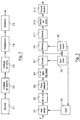
- Figure 1 shows a simplified block diagram of a transmitter of a data train signal according to the invention. The emission process is directly deduced therefrom.
- the coded data generated from these codes are then organized into data streams and modulated (14). They are therefore suitably distributed and interleaved on several data streams in order to provide the necessary diversity and to decorrelate the fading affecting the symbols transmitted. Reference elements are also introduced into each data stream, according to the distribution principles specified below. Finally, the data is modulated in phase.
- the baseband signal generated by the modulator 14 is obtained by filtering the formatting of the symbols making up this train.
- the shaping filter is generally a Nyquist root filter to avoid any IES at the output of the adapted filter of the receiver.
- the baseband signal thus generated is then transposed in frequency, amplified and transmitted (15) through the channel.
- TDMA time distributed multiple access technique
- the set of logical channels used by the ICO system is very close to that of GSM. It comprises, in particular, a TCH channel (“Traffic CHannel”) at the level of the uplink and downlink, a BCCH channel (“Broadcast Common Channel”) at the level of the downlink and a RACH channel (“Random Access Channel”) at the uplink.
- TCH Transmission CHannel
- BCCH Broadcast Common Channel
- RACH Random Access Channel
- the modulation adopted for the downlink is MDP4 for TCH and MDP2 for BCCH.
- the number of symbols per data stream is 120 (1 bit per symbol in MDP2; 2 bits per symbol in MDP4).
- the GMSK modulation with continuous phase, and therefore with memory, is retained at the level of the uplink, for reasons of non-linearity at the level of the mobile transmitters.
- the number of symbols transmitted is 240 for the TCH, and 120 for the RACH. In both cases, a transmitted symbol corresponds to a transmitted bit.
- the RACH channel conveys the identity of a mobile terminal that wants to access the services of the ICO system. It requires a higher link margin than traffic channels. For this reason, it implements a Golay code followed by a repetitive code (3.13).
- the reference symbols are distributed in several blocks (of at least one symbol) in each data stream.
- the number of symbols used for synchronization depends on the characteristics of the actual transmission channel.
- the transmission channel underlying the TCH logical channel is a Rice type channel (that is to say consisting of a direct path and a multi-path part with a relative delay almost zero relative to the latter. ) presenting a ratio K between the power of the direct path and that of the multipath favorable, with values of the order of 7 to 12 dB.
- the TCH channel can use as references only 10% of the symbols of the data stream, that is to say 12 reference symbols per data stream transmitted for the downlink, and 24 reference symbols per data stream transmitted for the uplink.
- Table 1 illustrates a layout mode in which the reference blocks include 2 reference symbols. This implantation is used for the TCH channel of the downlink.
- Table 1 symbol no. field length content of the field 0-1 2 guard symbols 2-8 7 useful symbols 9-10 2 explicit reference symbols 11-28 18 useful symbols 29-30 2 explicit reference symbols 31-48 18 useful symbols 49-50 2 explicit reference symbols 51-68 18 useful symbols 69-70 2 explicit reference symbols 71-88 18 useful symbols 89-90 2 explicit reference symbols 91-108 18 useful symbols 109-110 2 explicit reference symbols 111-117 7 useful symbols 118-119 2 guard symbols
- the BCCH logical channel is in particular used by mobile terminals to perform synchronization at the level of data trains.
- the underlying real transmission channel is of the Rice type with a value of K of the order of 0 dB. For these two reasons, 32 explicit reference symbols are provided.
- Table 3 illustrates the corresponding structure of the data stream.
- Table 3 symbol no. field length content of the field 0-1 2 guard symbols 2-8 7 useful symbols 9-10 2 explicit reference symbols 11-28 18 useful symbols 29-30 2 explicit reference symbols 31-46 16 useful symbols 47-72 26 explicit reference symbols (synchronization word) 73-88 16 useful symbols 89-90 2 explicit reference symbols 91-108 18 useful symbols 109-110 2 explicit reference symbols 111-117 7 useful symbols 118-119 2 guard symbols
- a part of these symbols can then be grouped in the middle of the data stream to keep acceptable performance in terms of synchronization and determination of the maximum opening of the eye diagram, at the level of the receiver.
- the other part is then distributed over the rest of the data stream, as is the case for the logical channel TCH.
- the RACH logical channel is used in the uplink by mobile terminals to request access to the services of the ICO system.
- the underlying real transmission channel is generally of the same type as that of the BCCH. Unlike the BCCH channel, which is repetitive, the RACH channel is transmitted in isolation, and must therefore be detected in a single pass. Therefore, the number of reference symbols is 44, (instead of 32 for the BCCH), as specified in Table 4.
- the implicit reference symbols are advantageously used to refine the estimation of the channel.
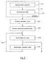
- Figure 2 illustrates an example of a signal receiver according to the invention as well as the corresponding reception method.
- the sampled signal is then demodulated (39). Furthermore, it supplies a synchronization module 36 and a module for estimating the transmission channel 38.
- the samples corresponding to a data stream are also used by the receiver to determine an estimate 38 according to the MAP criterion of the realization of the discrete channel at the level thereof.
- This estimation 38 is carried out by means of the simplified representation of the discrete channel at the level of the received data stream, the use of the EM algorithm and possibly of an algorithm such as that of Bahl [9].
- This iterative algorithm starts from arbitrary initial conditions which can be advantageously obtained thanks to the synchronization symbols known to the receiver.
- Synchronization distributed over the entire data train according to the invention proves to be of great utility because it makes it possible not only to avoid convergence of the algorithm towards local maxima of the conditional probability, but also to accelerate this convergence at lower cost.
- the receiver uses the estimate 38 at the MAP of the discrete channel at the level of a received data train to demodulate 39 according to a given criterion the symbols carrying information of this train.
- the demodulator 39 can in particular provide weighted outputs in order to improve the performance of the decoder 310.
- the channel estimation is also used by the receiver to control the progress of the preamplification 31, by means of the use of an automatic gain correction function (AGC) 35.
- AGC automatic gain correction function
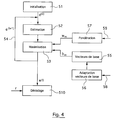
- This synchronization is then refined 412 by means of the symbols for synchronizing the data trains of the BCCH channel.
- the estimate 421, 422 of the discrete channel at the level of a received data stream is performed according to the MAP criterion. This estimation is carried out using the algorithm described below.
- the receiver firstly uses the synchronization symbols to establish suitable initial conditions 421 for the proper functioning of the iterative algorithm.
- the symmetry of the constellations of the MDP2 for the BCCH and of the MDP4 for the TCH then leads to a zero contribution of the information symbols in the calculation of the initial conditions of the iterative algorithm 44 of estimation of channel. These initial conditions are then used by this algorithm to improve the estimation of the channel 422, this time taking into account the additional contribution 432 of the coded information symbols.
- the IES due to the modulation memory and to the adjacent symbols not known does not affect the symbols in the middle of each grouping. These symbols in the middle of each grouping can then be used to calculate the initial conditions of the iterative algorithm.
- the iterative algorithm then uses the GMSK modulation trellis to also take into account the remaining synchronization symbols and coded information symbols (for example using the Bahl algorithm).
- the position chosen for the implicit reference symbols makes it possible to obtain a good interlacing of the words of the code with repetition (3,1,3).
- the consideration of the repetitive code (3,1,3) can be integrated directly into the estimation algorithm (in the case where the modulation memory can be neglected at the first order), it generates an imperceptible increase in the complexity of it.
- One aspect of the invention is based on a new simplified modeling and representation of the discrete channel seen at the output of the adapted filter of the receiver at the level of the sent data streams.
- the transmission channel is assumed to be of the Rice type. It consists of a direct path and a multi-path part with an almost zero relative delay with respect to the latter.
- the direct path is specified by a constant complex attenuation factor.
- the multipath part resulting from field reflections is characterized as a stationary Gaussian random process with zero mean [1, 16].
- This function is a power spectrum which gives the intensity of the transmission channel as a function of the Doppler frequency f. It is equal to the Fourier transform of the autocorrelation function ⁇ C ( ⁇ ) of the channel. It has a bounded support of width B D called Doppler extent of the channel. In the context of the invention, this extent is assumed to be small compared to the symbol rate 1 / T.
- the baseband signal corresponding to a data stream sent from N symbols is written, in the case of MDP modulation, in the form (easily adaptable to other types of modulation [1]): where T is the symbol period, x ( t ) is a unit standard Nyquist root formatting filter and the a k are complex symbols belonging to an arbitrary alphabet A.
- the module of these symbols is equal to the square root of the energy in baseband per symbol emitted 2 E s .
- the signal at the input of the receiver corresponds to the transmitted baseband signal distorted by the channel and corrupted by a complex additive white Gaussian noise of baseband spectral power 2 N 0 .
- the n k for their part, represent an embodiment of a discrete additive complex Gaussian noise. They are independent and have 2 N 0 as variance.
- the autocorrelation function, ⁇ c ( l ), of the discrete channel is deduced directly from that of the transmission channel, ⁇ C ( ⁇ ), by sampling it at symbol rate.
- One of the objectives of the invention is to propose an entirely news of the simplified representation of the achievements of the discrete channel at the level of the transmitted data streams.
- the vector c can then be decomposed into the form where the b k are the eigenvectors of the covariance matrix L of the vector c and the e k are independent complex Gaussian random variables whose variances are equal to the eigenvalues ⁇ k of the matrix L associated with the vectors b k divided by ⁇ c (0).
- the vectors b k form an orthonormal base of the complex canonical space with N dimensions.
- the corresponding eigenvalues are assumed to be arranged in descending order.
- Vector PD e ⁇ e 0 , e 1 , ... e N-1 t , denoted p ( e ), is equal to the product of the Gaussian PD of these components.
- the covariance matrix L is poorly conditioned because the Doppler spread B D is small compared to the clock rate 1 / T. Consequently, the eigenvalues ⁇ k have a very steep decay and vanish quickly.
- One of the contributions of the invention is to take advantage of these qualities of independence of the random variables e k and of rapid decrease of the eigenvalues ⁇ k to substantially reduce the complexity of the estimator of the discrete channel.
- the receiver has an incomplete knowledge of the characteristics of its local oscillator and those of the SPD S C ( f ) of the transmission channel.
- the SPD most unpredictable from the viewpoint of information theory [7] is a bounded support flat spectrum width equal to the Doppler spread B D.
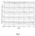
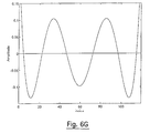
- the eigenvectors b k are equal in this case to the restrictions on the support of the SSAD data stream [8] well defined.
- the corresponding eigenvectors b k are also represented in FIGS. 6A to 6G.
- the PD of an embodiment c of the discrete channel at the level of a transmitted data stream is determined indirectly by the PD, p ( e ), of e which is of course well known to the receiver.
- the vector c can then be estimated according to the MAP criterion.
- the PDs of 2 N 0 and 2 E s ⁇ are generally unknown to the receiver. Their estimation is then generally accomplished according to the MV criterion.
- r (r 0, r 1, ..., r N-1) t
- a (a 0, a 1, ..., a N-1) t
- n (n 0 , n 1 , ..., n N-1 ) t the vectors of samples received, symbols transmitted and noise.
- some transmitted symbols are coded or fixed.
- the vector a of transmitted symbols is then characterized by the a priori discrete PD P ( a ).
- the MAP estimate ⁇ of c or equivalently, ê of e , is the value which maximizes the conditional PD a posteriori p ( e
- the iterative estimation (54) of e can be performed a finite number I of times. This number is chosen in such a way that the estimate e ( I ) reached is sufficiently close on average to the optimal estimate ê to guarantee an imperceptible degradation of the performance of the receiver.
- the weighting factors w m are also obtained in the case of the estimation of the discrete channel according to the least-squares method (MMC) with perfect knowledge of the transmitted data. They measure the quality of the contribution of a basic vector b m in the representation of the estimate to the MAP of the discrete channel.
- MMC least-squares method
- the coding structure can be integrated directly into the preceding formula.
- the value of the estimate of the channel towards which the EM algorithm converges is largely conditioned by the initial conditions used by this algorithm. If these initial conditions are poorly chosen, the EM algorithm can converge towards estimates, ê of e , corresponding to local maxima of the conditional PD a posteriori p ( e
- the choice of the location of these synchronization symbols in trains of transmitted data is not only decisive for the quality of the channel estimation but also for the good convergence of the EM algorithm towards the optimal estimation which maximizes p ( e
- the uniform distribution of the synchronization symbols at the level of the transmitted data streams is beneficial not only for a better estimation of the channel but also for a better stabilization and even an acceleration of the convergence of the algorithm EM.
- the EM algorithm has instabilities that can severely compromise the quality of the channel estimation.
- One of the contributions of the invention is to be able to stabilize this algorithm by taking into account part or all of the coded structure of the information symbols of the received data train.
- Simple codes such as repetitive codes whose code words are well interleaved at the level of the data streams can be advantageously used to accomplish this stabilization task at low cost.
- the detector or decoder 510 can be designed to minimize a given criterion. It can in particular minimize the probability of error of the information data or of the coded modulated symbols.
- This detector can take into account the memory of the phase modulation used or the coded structure of the symbols transmitted. This can be taken into account in particular via the Viterbi algorithm [11, 12], the Bahl algorithm [9] or the SOVA algorithm [10]. These last two algorithms can be used advantageously in the case where the receiver requires confidence values of the decoded data. This is particularly the case for communication systems using serial concatenated coding and where the external decoder needs weighted outputs of the internal code to improve its performance.
- the coding structure can be integrated directly into the preceding formula.
Landscapes
- Engineering & Computer Science (AREA)
- Computer Networks & Wireless Communication (AREA)
- Signal Processing (AREA)
- Power Engineering (AREA)
- Digital Transmission Methods That Use Modulated Carrier Waves (AREA)
- Mobile Radio Communication Systems (AREA)
Applications Claiming Priority (2)
| Application Number | Priority Date | Filing Date | Title |
|---|---|---|---|
| FR9605200 | 1996-04-19 | ||
| FR9605200A FR2747870B1 (fr) | 1996-04-19 | 1996-04-19 | Signal numerique a blocs de reference multiples pour l'estimation de canal, procedes d'estimation de canal et recepteurs correspondants |
Publications (3)
| Publication Number | Publication Date |
|---|---|
| EP0802656A2 true EP0802656A2 (de) | 1997-10-22 |
| EP0802656A3 EP0802656A3 (de) | 1998-01-14 |
| EP0802656B1 EP0802656B1 (de) | 2007-12-26 |
Family
ID=9491568
Family Applications (1)
| Application Number | Title | Priority Date | Filing Date |
|---|---|---|---|
| EP97460015A Expired - Lifetime EP0802656B1 (de) | 1996-04-19 | 1997-04-17 | Verfahren zur Kanalschätzung und entsprechender Empfänger |
Country Status (5)
| Country | Link |
|---|---|
| US (1) | US6263029B1 (de) |
| EP (1) | EP0802656B1 (de) |
| CN (1) | CN1173088A (de) |
| DE (1) | DE69738414D1 (de) |
| FR (1) | FR2747870B1 (de) |
Cited By (17)
| Publication number | Priority date | Publication date | Assignee | Title |
|---|---|---|---|---|
| FR2777408A1 (fr) * | 1998-04-10 | 1999-10-15 | Nortel Matra Cellular | Procede de synchronisation fine sur un signal recu d'un canal de transmission |
| WO2000014896A1 (de) * | 1998-09-04 | 2000-03-16 | Siemens Aktiengesellschaft | Kanalimpulsantwortschätzung |
| WO2000033527A1 (en) * | 1998-11-30 | 2000-06-08 | Ericsson, Inc. | Systems and methods for receiving a modulated signal containing encoded and unencoded bits using multi-pass demodulation |
| WO2000033526A1 (en) * | 1998-11-30 | 2000-06-08 | Ericsson, Inc. | Adaptive channel characterization using decoded symbols |
| WO2000036760A1 (en) * | 1998-12-16 | 2000-06-22 | Telefonaktiebolaget Lm Ericsson (Publ) | Channel estimation for a cdma system using pre-defined symbols in addition to pilot symbols |
| FR2794589A1 (fr) * | 1999-06-02 | 2000-12-08 | France Telecom | Procede de communications radiomobiles amrt iteratif |
| WO2001013595A1 (de) * | 1999-08-16 | 2001-02-22 | Siemens Aktiengesellschaft | Verfahren zur kanalschätzung in einem funk-kommunikationssystem wobei kanalmesssequenzen durch zyklische ableitung von grundsequenzen gebildet werden |
| WO2001058105A1 (en) * | 2000-02-07 | 2001-08-09 | At & T Corp. | System and method for near optimal joint channel estimation and data detection for cofdm systems |
| GB2360425A (en) * | 2000-03-16 | 2001-09-19 | Siemens Ag | Channel state information estimation for turbo-code decoders |
| US6477210B2 (en) | 2000-02-07 | 2002-11-05 | At&T Corp. | System for near optimal joint channel estimation and data detection for COFDM systems |
| WO2002098095A1 (fr) * | 2001-05-30 | 2002-12-05 | Wavecom | Procédé d'estimation de la fonction de transfert d'un canal de transmission d'un signal multiporteuse et récepteur correspondant |
| EP0984562A3 (de) * | 1998-09-03 | 2003-05-28 | Nec Corporation | Piloteninterpolationsynchrondetektion in einem Rake-Empfänger |
| EP0978969A3 (de) * | 1998-08-05 | 2004-01-14 | Nec Corporation | Verfahren und Gerät zur Demodulation eines ein Pilotsignal enthaltenden Empfangssignals |
| FR2859338A1 (fr) * | 2003-09-01 | 2005-03-04 | France Telecom | Procede d'estimation de canal par projection sur des familles orthogonales de construction particuliere et recepteur correspondant |
| FR2859337A1 (fr) * | 2003-09-01 | 2005-03-04 | France Telecom | Procede d'estimation de canal par projection sur des familles orthogonales obtenues par modelisation de la reponse impulsionnelle du canal, et recepteur correspondant |
| FR2861927A1 (fr) * | 2004-12-07 | 2005-05-06 | Wavecom | Procede de transmission d'une estimation d'au moins un canal de propagation d'un recepteur vers un emetteur, emetteur et recepteur correspondants |
| FR2861928A1 (fr) * | 2003-10-31 | 2005-05-06 | Wavecom | Procede de transmission d'une estimation d'au moins un canal de propagation d'un recepteur vers un emetteur, emetteur et recepteur correspondants |
Families Citing this family (19)
| Publication number | Priority date | Publication date | Assignee | Title |
|---|---|---|---|---|
| US7072414B1 (en) * | 1999-09-07 | 2006-07-04 | The Aerospace Corporation | Gaussian minimum shift keying (GMSK) precoding communication method |
| US6463105B1 (en) * | 1999-09-13 | 2002-10-08 | Ericsson Inc. | Methods and systems for estimation of the carrier to interference ratio for a wireless communication channel |
| EP1234402B1 (de) * | 1999-12-01 | 2006-03-08 | Telefonaktiebolaget LM Ericsson (publ) | Bitfehlerratenschätzung von pilotsignalen |
| US6901120B2 (en) * | 2000-12-06 | 2005-05-31 | Telefonaktiebolaget L M Ericsson (Publ) | Method and apparatus for iterative parameter estimation |
| US6842494B2 (en) * | 2001-08-31 | 2005-01-11 | Nokia Corporation | Apparatus, and associated method, for forming a systematic, recursive, space-time code |
| GB0124952D0 (en) * | 2001-10-17 | 2001-12-05 | Nokia Corp | A receiver and a receiving method |
| US7020222B2 (en) * | 2001-10-24 | 2006-03-28 | Texas Instruments Incorporated | Efficient method and system for offset phasor determination |
| US7324606B2 (en) * | 2001-10-31 | 2008-01-29 | Henry Stephen Eilts | Computationally efficient system and method for channel estimation |
| US7308232B2 (en) * | 2002-06-21 | 2007-12-11 | Lucent Technologies Inc. | Method and apparatus for estimating a channel based on channel statistics |
| US8325854B2 (en) * | 2002-07-12 | 2012-12-04 | Alcatel Lucent | Techniques for communicating over single-or multiple-antenna channels having both temporal and spectral fluctuations |
| KR100560386B1 (ko) * | 2003-12-17 | 2006-03-13 | 한국전자통신연구원 | 무선 통신 시스템의 상향 링크에서 코히어런트 검출을위한 직교주파수 분할 다중 접속 방식의 송수신 장치 및그 방법 |
| US7779326B2 (en) * | 2005-03-01 | 2010-08-17 | The Texas A&M University System | Multi-source data encoding, transmission and decoding using Slepian-Wolf codes based on channel code partitioning |
| US7295137B2 (en) * | 2005-03-01 | 2007-11-13 | The Texas A&M University System | Data encoding and decoding using Slepian-Wolf coded nested quantization to achieve Wyner-Ziv coding |
| US7256716B2 (en) * | 2005-03-01 | 2007-08-14 | The Texas A&M University System | Data encoding and decoding using Slepian-Wolf coded nested quantization to achieve Wyner-Ziv coding |
| US8077816B2 (en) * | 2007-09-04 | 2011-12-13 | Freescale Semiconductor, Inc. | Fast predictive automatic gain control for dynamic range reduction in wireless communication receiver |
| US8031670B2 (en) * | 2008-11-13 | 2011-10-04 | Telefonaktiebolaget L M Ericsson (Publ) | Systems and methods for selecting the size of a control region of a downlink subframe |
| WO2013132926A1 (ja) * | 2012-03-06 | 2013-09-12 | 日本電信電話株式会社 | 雑音推定装置、雑音推定方法、雑音推定プログラム及び記録媒体 |
| US10862608B2 (en) * | 2018-12-04 | 2020-12-08 | National Cheng Kung University | Communication device and communication method |
| CN109581319B (zh) * | 2019-01-24 | 2023-02-10 | 西安电子科技大学 | 基于多扫描递归的海杂波多普勒偏移和带宽估计方法 |
Family Cites Families (11)
| Publication number | Priority date | Publication date | Assignee | Title |
|---|---|---|---|---|
| US5127051A (en) * | 1988-06-13 | 1992-06-30 | Itt Corporation | Adaptive modem for varying communication channel |
| DE4201810A1 (de) * | 1992-01-24 | 1993-07-29 | Aeg Mobile Communication | Digitales nachrichtenuebertragungssystem |
| JPH06140951A (ja) * | 1992-10-27 | 1994-05-20 | Sony Corp | ビタビ等化器 |
| US5818876A (en) * | 1993-02-01 | 1998-10-06 | Motorola, Inc. | Method and apparatus of adaptive maximum likelihood sequence estimation using a variable convergence step size |
| US5329547A (en) * | 1993-03-11 | 1994-07-12 | Motorola, Inc. | Method and apparatus for coherent communication in a spread-spectrum communication system |
| US5371760A (en) * | 1993-04-28 | 1994-12-06 | Telesis Technologies Laboratory | Method and apparatus for measuring the impulse response of a radio channel |
| US5581580A (en) * | 1993-05-20 | 1996-12-03 | Telefonaktiebolaget Lm Ericsson | Low complexity model based channel estimation algorithm for fading channels |
| SE9302453L (sv) * | 1993-07-20 | 1994-10-17 | Telia Ab | Förfarande och anordning för synkronisering i digitalt transmissionssystem av typen OFDM |
| US5371471A (en) * | 1993-10-29 | 1994-12-06 | General Electric Company | Low complexity adaptive equalizer radio receiver employing direct reference state updates |
| US5539412A (en) * | 1994-04-29 | 1996-07-23 | Litton Systems, Inc. | Radar system with adaptive clutter suppression |
| JP3118548B2 (ja) * | 1994-06-22 | 2000-12-18 | 株式会社エヌ・ティ・ティ・ドコモ | ディジタル通信受信機用同期検波装置および同期方法 |
-
1996
- 1996-04-19 FR FR9605200A patent/FR2747870B1/fr not_active Expired - Fee Related
-
1997
- 1997-04-17 DE DE69738414T patent/DE69738414D1/de not_active Expired - Lifetime
- 1997-04-17 US US08/839,255 patent/US6263029B1/en not_active Expired - Lifetime
- 1997-04-17 EP EP97460015A patent/EP0802656B1/de not_active Expired - Lifetime
- 1997-04-19 CN CN97113024A patent/CN1173088A/zh active Pending
Cited By (29)
| Publication number | Priority date | Publication date | Assignee | Title |
|---|---|---|---|---|
| WO1999053645A1 (fr) * | 1998-04-10 | 1999-10-21 | Nortel Matra Cellular | Procede de synchronisation fine sur un signal recu d'un canal de transmission |
| FR2777408A1 (fr) * | 1998-04-10 | 1999-10-15 | Nortel Matra Cellular | Procede de synchronisation fine sur un signal recu d'un canal de transmission |
| EP0978969A3 (de) * | 1998-08-05 | 2004-01-14 | Nec Corporation | Verfahren und Gerät zur Demodulation eines ein Pilotsignal enthaltenden Empfangssignals |
| EP0984562A3 (de) * | 1998-09-03 | 2003-05-28 | Nec Corporation | Piloteninterpolationsynchrondetektion in einem Rake-Empfänger |
| US6912259B1 (en) | 1998-09-03 | 2005-06-28 | Nec Corporation | Interpolation synchronous detection method and radio communication system |
| WO2000014896A1 (de) * | 1998-09-04 | 2000-03-16 | Siemens Aktiengesellschaft | Kanalimpulsantwortschätzung |
| US6320919B1 (en) | 1998-11-30 | 2001-11-20 | Ericsson Inc. | Adaptive channel characterization using decoded symbols |
| WO2000033527A1 (en) * | 1998-11-30 | 2000-06-08 | Ericsson, Inc. | Systems and methods for receiving a modulated signal containing encoded and unencoded bits using multi-pass demodulation |
| WO2000033526A1 (en) * | 1998-11-30 | 2000-06-08 | Ericsson, Inc. | Adaptive channel characterization using decoded symbols |
| GB2363553A (en) * | 1998-12-16 | 2001-12-19 | Ericsson Telefon Ab L M | Channel estimation for a CDMA system using pre-defined symbols in addition to pilot symbols |
| GB2363553B (en) * | 1998-12-16 | 2003-12-03 | Ericsson Telefon Ab L M | Channel estimation for a CDMA system using pre-defined symbols in addition to pilot symbols |
| WO2000036760A1 (en) * | 1998-12-16 | 2000-06-22 | Telefonaktiebolaget Lm Ericsson (Publ) | Channel estimation for a cdma system using pre-defined symbols in addition to pilot symbols |
| WO2000076160A1 (fr) * | 1999-06-02 | 2000-12-14 | France Telecom | Procede de communications radiomobiles amrt iteratif |
| US6990092B1 (en) * | 1999-06-02 | 2006-01-24 | France Telecom | Iterative process for TDMA radiomobile communications |
| FR2794589A1 (fr) * | 1999-06-02 | 2000-12-08 | France Telecom | Procede de communications radiomobiles amrt iteratif |
| WO2001013595A1 (de) * | 1999-08-16 | 2001-02-22 | Siemens Aktiengesellschaft | Verfahren zur kanalschätzung in einem funk-kommunikationssystem wobei kanalmesssequenzen durch zyklische ableitung von grundsequenzen gebildet werden |
| WO2001058105A1 (en) * | 2000-02-07 | 2001-08-09 | At & T Corp. | System and method for near optimal joint channel estimation and data detection for cofdm systems |
| US6477210B2 (en) | 2000-02-07 | 2002-11-05 | At&T Corp. | System for near optimal joint channel estimation and data detection for COFDM systems |
| GB2360425A (en) * | 2000-03-16 | 2001-09-19 | Siemens Ag | Channel state information estimation for turbo-code decoders |
| WO2002098095A1 (fr) * | 2001-05-30 | 2002-12-05 | Wavecom | Procédé d'estimation de la fonction de transfert d'un canal de transmission d'un signal multiporteuse et récepteur correspondant |
| FR2825551A1 (fr) * | 2001-05-30 | 2002-12-06 | Wavecom Sa | Procede d'estimation de la fonction de transfert d'un canal de transmission d'un signal multiporteuse, procede de reception d'un signal numerique, et recepteur d'un signal multiporteuse correspondants |
| US7242721B2 (en) | 2001-05-30 | 2007-07-10 | Wavecom | Method for estimating the transfer function of a multicarrier signal transmission channel and corresponding receiver |
| FR2859337A1 (fr) * | 2003-09-01 | 2005-03-04 | France Telecom | Procede d'estimation de canal par projection sur des familles orthogonales obtenues par modelisation de la reponse impulsionnelle du canal, et recepteur correspondant |
| WO2005025162A1 (fr) * | 2003-09-01 | 2005-03-17 | France Telecom | Procede d’estimation de canal par projection sur des familles orthogonales de construction particuliere et recepteur correspondant |
| WO2005025161A1 (fr) * | 2003-09-01 | 2005-03-17 | France Telecom | Procede d’estimation de canal par projection sur des familles orthogonales obtenues par modelisation de la reponse impulsionnelle du canal, et recepteur correspondant |
| FR2859338A1 (fr) * | 2003-09-01 | 2005-03-04 | France Telecom | Procede d'estimation de canal par projection sur des familles orthogonales de construction particuliere et recepteur correspondant |
| FR2861928A1 (fr) * | 2003-10-31 | 2005-05-06 | Wavecom | Procede de transmission d'une estimation d'au moins un canal de propagation d'un recepteur vers un emetteur, emetteur et recepteur correspondants |
| WO2005043801A3 (fr) * | 2003-10-31 | 2005-08-04 | Wavecom | Procede de transmission de donnees d’une estimation d'un canal de propagation d’un recepteur vers un emetteur |
| FR2861927A1 (fr) * | 2004-12-07 | 2005-05-06 | Wavecom | Procede de transmission d'une estimation d'au moins un canal de propagation d'un recepteur vers un emetteur, emetteur et recepteur correspondants |
Also Published As
| Publication number | Publication date |
|---|---|
| EP0802656A3 (de) | 1998-01-14 |
| FR2747870B1 (fr) | 1998-11-06 |
| US6263029B1 (en) | 2001-07-17 |
| FR2747870A1 (fr) | 1997-10-24 |
| DE69738414D1 (de) | 2008-02-07 |
| CN1173088A (zh) | 1998-02-11 |
| EP0802656B1 (de) | 2007-12-26 |
Similar Documents
| Publication | Publication Date | Title |
|---|---|---|
| EP0802656B1 (de) | Verfahren zur Kanalschätzung und entsprechender Empfänger | |
| EP2220803B1 (de) | Störminderung bei einem ofdm-signal mit gewichtungsvektorbildung in untervektorräumen | |
| EP1988656B1 (de) | Dekodierung von Signalsymbolen, die nach Frequenz- und Zeitdimensionen aufgeschlüsselt sind | |
| EP1168739B1 (de) | Verfahren und Vorrichtung zur Schätzung der Impulsantwort eines Übertragungskanals, insbesondere für ein zellulares Mobiltelefon | |
| EP1391095B1 (de) | Verfahren zur schätzung der übertragungsfunktion eines mehrträger-signalübertragungskanals und eines entsprechenden empfängers | |
| EP0594505B1 (de) | Verfahren zur hierarchischen Kodierung/Dekodierung eines digitalen Signals, und entsprechendes System zur Anwendung bei digitalem Fernsehen | |
| WO2010029172A1 (fr) | Methode d'estimation aveugle de parametres de modulation ofdm selon un critere de maximum de vraisemblance | |
| EP0549445B1 (de) | Verfahren zur Übertragung von Referenzsignalen in einem Mehrträgerdatenübertragungssystem | |
| EP2904754B1 (de) | Verfahren zur übertragung eines mehrträgersignals sowie entsprechende übertragungsvorrichtung und computerprogramm | |
| WO2000076160A1 (fr) | Procede de communications radiomobiles amrt iteratif | |
| EP3912317B1 (de) | Verfahren zum empfangen eines soqpsk-tg-signals mit pam-zerlegung | |
| FR2742613A1 (fr) | Procede d'evaluation d'un facteur de qualite representatif d'un canal de transmission d'un signal numerique, et recepteur correspondant | |
| FR2805102A1 (fr) | Procedes et dispositifs d'emission et de reception d'information, et systemes les mettant en oeuvre | |
| EP2179519B1 (de) | Signalübertragung mithilfe mehrerer antennen | |
| EP3780529B1 (de) | Vorrichtung und verfahren für die signalisierung von kommunikationen über ein fragmentiertes spektrum | |
| EP1081855B1 (de) | Verfahren und vorrichtung zur synchronisation eines kommunikationsempfängers | |
| EP1206091B1 (de) | Verfahren und Vorrichtung zur Kanalschätzung, insbesondere für eine Mobiltelefon | |
| EP0648037B1 (de) | Phasenabgleich im Basisband | |
| EP0858196A1 (de) | Entzerrer und Kanaldekoder | |
| FR2934102A1 (fr) | Procede de synchronisation temporelle d'un signal numerique, dispositif et produit programme d'ordinateur correspondants | |
| EP0821500B1 (de) | Mehrfachdekodierung | |
| Jerbi | Non-coherent detection of continuous phase modulation for low earth orbit satellite IoT communications affected by Doppler shift | |
| FR2805690A1 (fr) | Procede d'estimation d'un ecart de frequence radio, et recepteur de radiocommunication mettant en oeuvre le procede | |
| EP1128590A1 (de) | Synchronisierungssystem für ein digitales telekommunikationssystem mit vielfachzugriff | |
| EP2368328A1 (de) | Verfahren zum emittieren von impulsen in einem übertragungskanal |
Legal Events
| Date | Code | Title | Description |
|---|---|---|---|
| PUAI | Public reference made under article 153(3) epc to a published international application that has entered the european phase |
Free format text: ORIGINAL CODE: 0009012 |
|
| AK | Designated contracting states |
Kind code of ref document: A2 Designated state(s): DE ES FI GB IT SE |
|
| PUAL | Search report despatched |
Free format text: ORIGINAL CODE: 0009013 |
|
| AK | Designated contracting states |
Kind code of ref document: A3 Designated state(s): DE ES FI GB IT SE |
|
| 17P | Request for examination filed |
Effective date: 19980325 |
|
| 17Q | First examination report despatched |
Effective date: 20031219 |
|
| 17Q | First examination report despatched |
Effective date: 20031219 |
|
| GRAP | Despatch of communication of intention to grant a patent |
Free format text: ORIGINAL CODE: EPIDOSNIGR1 |
|
| RTI1 | Title (correction) |
Free format text: METHOD OF CHANNEL ESTIMATION AND CORRESPONDING RECEIVER |
|
| RAP1 | Party data changed (applicant data changed or rights of an application transferred) |
Owner name: WAVECOM |
|
| GRAS | Grant fee paid |
Free format text: ORIGINAL CODE: EPIDOSNIGR3 |
|
| GRAA | (expected) grant |
Free format text: ORIGINAL CODE: 0009210 |
|
| AK | Designated contracting states |
Kind code of ref document: B1 Designated state(s): DE ES FI GB IT SE |
|
| REG | Reference to a national code |
Ref country code: GB Ref legal event code: FG4D Free format text: NOT ENGLISH |
|
| RAP2 | Party data changed (patent owner data changed or rights of a patent transferred) |
Owner name: WAVECOM |
|
| REF | Corresponds to: |
Ref document number: 69738414 Country of ref document: DE Date of ref document: 20080207 Kind code of ref document: P |
|
| PG25 | Lapsed in a contracting state [announced via postgrant information from national office to epo] |
Ref country code: SE Free format text: LAPSE BECAUSE OF FAILURE TO SUBMIT A TRANSLATION OF THE DESCRIPTION OR TO PAY THE FEE WITHIN THE PRESCRIBED TIME-LIMIT Effective date: 20080326 |
|
| PG25 | Lapsed in a contracting state [announced via postgrant information from national office to epo] |
Ref country code: FI Free format text: LAPSE BECAUSE OF FAILURE TO SUBMIT A TRANSLATION OF THE DESCRIPTION OR TO PAY THE FEE WITHIN THE PRESCRIBED TIME-LIMIT Effective date: 20071226 |
|
| GBV | Gb: ep patent (uk) treated as always having been void in accordance with gb section 77(7)/1977 [no translation filed] | ||
| PG25 | Lapsed in a contracting state [announced via postgrant information from national office to epo] |
Ref country code: ES Free format text: LAPSE BECAUSE OF FAILURE TO SUBMIT A TRANSLATION OF THE DESCRIPTION OR TO PAY THE FEE WITHIN THE PRESCRIBED TIME-LIMIT Effective date: 20080406 |
|
| PG25 | Lapsed in a contracting state [announced via postgrant information from national office to epo] |
Ref country code: DE Free format text: LAPSE BECAUSE OF FAILURE TO SUBMIT A TRANSLATION OF THE DESCRIPTION OR TO PAY THE FEE WITHIN THE PRESCRIBED TIME-LIMIT Effective date: 20080327 |
|
| PLBE | No opposition filed within time limit |
Free format text: ORIGINAL CODE: 0009261 |
|
| STAA | Information on the status of an ep patent application or granted ep patent |
Free format text: STATUS: NO OPPOSITION FILED WITHIN TIME LIMIT |
|
| 26N | No opposition filed |
Effective date: 20080929 |
|
| PG25 | Lapsed in a contracting state [announced via postgrant information from national office to epo] |
Ref country code: GB Free format text: LAPSE BECAUSE OF FAILURE TO SUBMIT A TRANSLATION OF THE DESCRIPTION OR TO PAY THE FEE WITHIN THE PRESCRIBED TIME-LIMIT Effective date: 20071226 |
|
| PG25 | Lapsed in a contracting state [announced via postgrant information from national office to epo] |
Ref country code: IT Free format text: LAPSE BECAUSE OF NON-PAYMENT OF DUE FEES Effective date: 20080430 |