EP0802656A2 - Digital signal with several reference blocks, for channel estimation; methods of channel estimation and corresponding receivers - Google Patents
Digital signal with several reference blocks, for channel estimation; methods of channel estimation and corresponding receivers Download PDFInfo
- Publication number
- EP0802656A2 EP0802656A2 EP97460015A EP97460015A EP0802656A2 EP 0802656 A2 EP0802656 A2 EP 0802656A2 EP 97460015 A EP97460015 A EP 97460015A EP 97460015 A EP97460015 A EP 97460015A EP 0802656 A2 EP0802656 A2 EP 0802656A2
- Authority
- EP
- European Patent Office
- Prior art keywords
- symbols
- channel
- estimate
- receiver
- estimation
- Prior art date
- Legal status (The legal status is an assumption and is not a legal conclusion. Google has not performed a legal analysis and makes no representation as to the accuracy of the status listed.)
- Granted
Links
Images


Classifications
-
- H—ELECTRICITY
- H04—ELECTRIC COMMUNICATION TECHNIQUE
- H04L—TRANSMISSION OF DIGITAL INFORMATION, e.g. TELEGRAPHIC COMMUNICATION
- H04L25/00—Baseband systems
- H04L25/02—Details ; arrangements for supplying electrical power along data transmission lines
- H04L25/0202—Channel estimation
- H04L25/0224—Channel estimation using sounding signals
- H04L25/0226—Channel estimation using sounding signals sounding signals per se
-
- H—ELECTRICITY
- H04—ELECTRIC COMMUNICATION TECHNIQUE
- H04L—TRANSMISSION OF DIGITAL INFORMATION, e.g. TELEGRAPHIC COMMUNICATION
- H04L1/00—Arrangements for detecting or preventing errors in the information received
- H04L1/08—Arrangements for detecting or preventing errors in the information received by repeating transmission, e.g. Verdan system
-
- H—ELECTRICITY
- H04—ELECTRIC COMMUNICATION TECHNIQUE
- H04L—TRANSMISSION OF DIGITAL INFORMATION, e.g. TELEGRAPHIC COMMUNICATION
- H04L25/00—Baseband systems
- H04L25/02—Details ; arrangements for supplying electrical power along data transmission lines
- H04L25/0202—Channel estimation
- H04L25/0224—Channel estimation using sounding signals
- H04L25/0228—Channel estimation using sounding signals with direct estimation from sounding signals
- H04L25/023—Channel estimation using sounding signals with direct estimation from sounding signals with extension to other symbols
- H04L25/0236—Channel estimation using sounding signals with direct estimation from sounding signals with extension to other symbols using estimation of the other symbols
Definitions
- the field of the invention is that of the transmission of digital data, in particular in transmission channels having, or which may have, high Doppler fading and low symbol interference (IES). More specifically, the invention relates to the estimation of the transmission channel and the demodulation in receivers of signals transmitted through such channels.
- IES Doppler fading and low symbol interference
- a privileged, although not exclusive, field of application of the invention is that of digital communications between satellites and mobiles. It can be envisaged in particular within the framework of the ICO and Iridium projects. More generally, the invention advantageously applies in all communications systems where the channel has a high Doppler and a low IES.
- the synchronization symbols are consecutive and form a synchronization sequence, generally placed at the start of the data streams. Synchronization at the receiver is achieved by detecting that the correlation of the samples received with those of the sequence used for synchronization has exceeded the threshold. This synchronization allows on the one hand the detection of the start of a data train and on the other hand the determination with precision of the instants of maximum opening of the diagram of the eye.
- the basic principle of time synchronization and channel estimation by the receiver is to transmit a sequence of symbols known to it by the data streams sent by the transmitter. By using a few predefined algorithms, these symbols are used to guarantee not only good synchronization of the receiver, but also a reliable estimate of the channel, thus allowing a good progress of the demodulation phase.
- the invention also aims to provide such signals which are simple to construct, at the level of the transmitters, and simple to decode and analyze in the receivers. Another objective of the invention is also to limit the losses in useful throughput, and therefore limit the number of reference data required.
- An additional objective of the invention is to provide a channel estimator which can significantly improve its performance by taking into account all or part of the coded structure of the transmitted data.
- the invention relates in particular to a digital signal, organized in consecutive data streams each comprising a predetermined number of successive symbols, and intended to be transmitted to at least one receiver, in a transmission channel which may have variations.
- each of said data streams comprising at least two distinct reference blocks for estimating said channel, distributed among the useful symbols representative of the source signal to be transmitted, each of said reference blocks being formed by at least one reference symbol (also sometimes called subsequently synchronization symbol, when it is also used for synchronization) known to the receiver and / or identifiable by said receiver.
- a second method for estimating a transmission channel of such a digital signal comprises a step of writing said estimate in the form of a combination of predetermined basic functions, with a bandwidth greater than or equal to that of the Doppler power spectrum (SPD) of said signal.
- SPD Doppler power spectrum
- said basic functions are restrictions on discrete flattened spheroidal sequences (SSAD, known in the English literature under the name of "Discrete Prolate Spheroidal Sequences”) [8].
- SSAD discrete flattened spheroidal sequences
- This type of function makes it possible to obtain a very precise estimate of the channel, from a reduced number of basic functions (for example 3 to 8).
- this method comprises a preliminary step of adaptation of the characteristics of said basic functions, in particular as a function of said Doppler power spectrum.
- a base is thus obtained which is best suited to the channel to be estimated.
- the invention also relates, of course, to the channel estimation devices and the receivers implementing the methods described above, as well as the signal transmitters and receivers according to the invention.
- an objective of the invention is to provide for a Doppler channel and a communication system of given characteristics the most suitable synchronization pattern.
- This pattern must be sufficiently distributed over a more or less extensive part of the data streams to characterize and estimate as well as possible the significant variations of the channel and distribute the coded data as well as possible. It should therefore not favor the performance of the receiver in terms of synchronization at the cost of sacrificing the quality of the channel estimation and the interleaving of the coded data.
- the corresponding channel estimation method proposed according to the invention is based in particular on a suitable modeling of the real channel and a new and simplified representation thereof.
- This representation must take into account as much as possible all the information known on the channel. This information must include at least the maximum width of the Doppler band, which must be known to the receiver.
- the algorithm adopts a flat modeling of this one.
- This modeling is best suited from the point of view of information theory because it leads to a maximum channel entropy [7].
- the discrete channel can be written as a combination of the restrictions on discrete flattened spheroidal sequences (SSAD) on the support of the data stream to be demodulated.
- SSADs discrete flattened spheroidal sequences
- the criterion MV is best suited to the problems of estimating the energy per symbol emitted or the variance of noise at the output of a given filter, when these are not known by the receiver.
- the MAP criterion is best suited to the problem of estimating the discrete channel at the level of transmitted data streams.
- the receiver implements the EM algorithm to perform an iterative estimation of a part or of all of these parameters according to the corresponding criteria.
- This algorithm avoids the systematic use of classic grouped synchronization patterns, which owe their success to their exploitation immediate by intuitive and simple algorithms.
- the choice of the location of the reference symbols in the data streams is indeed important for the performance of the channel estimator. It is also of capital importance in the correct determination of the initial conditions of the EM algorithm. Indeed, this generally tends to converge towards local maxima of the conditional probability (defined as the posterior probability of a realization of the channel conditionally on the received signal), if the location of the synchronization symbols is poorly chosen.
- the receiver performs in a standard manner a demodulation and / or a decoding of the information data received according to the criterion of the MV.
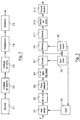
- Figure 1 shows a simplified block diagram of a transmitter of a data train signal according to the invention. The emission process is directly deduced therefrom.
- the coded data generated from these codes are then organized into data streams and modulated (14). They are therefore suitably distributed and interleaved on several data streams in order to provide the necessary diversity and to decorrelate the fading affecting the symbols transmitted. Reference elements are also introduced into each data stream, according to the distribution principles specified below. Finally, the data is modulated in phase.
- the baseband signal generated by the modulator 14 is obtained by filtering the formatting of the symbols making up this train.
- the shaping filter is generally a Nyquist root filter to avoid any IES at the output of the adapted filter of the receiver.
- the baseband signal thus generated is then transposed in frequency, amplified and transmitted (15) through the channel.
- TDMA time distributed multiple access technique
- the set of logical channels used by the ICO system is very close to that of GSM. It comprises, in particular, a TCH channel (“Traffic CHannel”) at the level of the uplink and downlink, a BCCH channel (“Broadcast Common Channel”) at the level of the downlink and a RACH channel (“Random Access Channel”) at the uplink.
- TCH Transmission CHannel
- BCCH Broadcast Common Channel
- RACH Random Access Channel
- the modulation adopted for the downlink is MDP4 for TCH and MDP2 for BCCH.
- the number of symbols per data stream is 120 (1 bit per symbol in MDP2; 2 bits per symbol in MDP4).
- the GMSK modulation with continuous phase, and therefore with memory, is retained at the level of the uplink, for reasons of non-linearity at the level of the mobile transmitters.
- the number of symbols transmitted is 240 for the TCH, and 120 for the RACH. In both cases, a transmitted symbol corresponds to a transmitted bit.
- the RACH channel conveys the identity of a mobile terminal that wants to access the services of the ICO system. It requires a higher link margin than traffic channels. For this reason, it implements a Golay code followed by a repetitive code (3.13).
- the reference symbols are distributed in several blocks (of at least one symbol) in each data stream.
- the number of symbols used for synchronization depends on the characteristics of the actual transmission channel.
- the transmission channel underlying the TCH logical channel is a Rice type channel (that is to say consisting of a direct path and a multi-path part with a relative delay almost zero relative to the latter. ) presenting a ratio K between the power of the direct path and that of the multipath favorable, with values of the order of 7 to 12 dB.
- the TCH channel can use as references only 10% of the symbols of the data stream, that is to say 12 reference symbols per data stream transmitted for the downlink, and 24 reference symbols per data stream transmitted for the uplink.
- Table 1 illustrates a layout mode in which the reference blocks include 2 reference symbols. This implantation is used for the TCH channel of the downlink.
- Table 1 symbol no. field length content of the field 0-1 2 guard symbols 2-8 7 useful symbols 9-10 2 explicit reference symbols 11-28 18 useful symbols 29-30 2 explicit reference symbols 31-48 18 useful symbols 49-50 2 explicit reference symbols 51-68 18 useful symbols 69-70 2 explicit reference symbols 71-88 18 useful symbols 89-90 2 explicit reference symbols 91-108 18 useful symbols 109-110 2 explicit reference symbols 111-117 7 useful symbols 118-119 2 guard symbols
- the BCCH logical channel is in particular used by mobile terminals to perform synchronization at the level of data trains.
- the underlying real transmission channel is of the Rice type with a value of K of the order of 0 dB. For these two reasons, 32 explicit reference symbols are provided.
- Table 3 illustrates the corresponding structure of the data stream.
- Table 3 symbol no. field length content of the field 0-1 2 guard symbols 2-8 7 useful symbols 9-10 2 explicit reference symbols 11-28 18 useful symbols 29-30 2 explicit reference symbols 31-46 16 useful symbols 47-72 26 explicit reference symbols (synchronization word) 73-88 16 useful symbols 89-90 2 explicit reference symbols 91-108 18 useful symbols 109-110 2 explicit reference symbols 111-117 7 useful symbols 118-119 2 guard symbols
- a part of these symbols can then be grouped in the middle of the data stream to keep acceptable performance in terms of synchronization and determination of the maximum opening of the eye diagram, at the level of the receiver.
- the other part is then distributed over the rest of the data stream, as is the case for the logical channel TCH.
- the RACH logical channel is used in the uplink by mobile terminals to request access to the services of the ICO system.
- the underlying real transmission channel is generally of the same type as that of the BCCH. Unlike the BCCH channel, which is repetitive, the RACH channel is transmitted in isolation, and must therefore be detected in a single pass. Therefore, the number of reference symbols is 44, (instead of 32 for the BCCH), as specified in Table 4.
- the implicit reference symbols are advantageously used to refine the estimation of the channel.
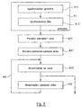
- Figure 2 illustrates an example of a signal receiver according to the invention as well as the corresponding reception method.
- the sampled signal is then demodulated (39). Furthermore, it supplies a synchronization module 36 and a module for estimating the transmission channel 38.
- the samples corresponding to a data stream are also used by the receiver to determine an estimate 38 according to the MAP criterion of the realization of the discrete channel at the level thereof.
- This estimation 38 is carried out by means of the simplified representation of the discrete channel at the level of the received data stream, the use of the EM algorithm and possibly of an algorithm such as that of Bahl [9].
- This iterative algorithm starts from arbitrary initial conditions which can be advantageously obtained thanks to the synchronization symbols known to the receiver.
- Synchronization distributed over the entire data train according to the invention proves to be of great utility because it makes it possible not only to avoid convergence of the algorithm towards local maxima of the conditional probability, but also to accelerate this convergence at lower cost.
- the receiver uses the estimate 38 at the MAP of the discrete channel at the level of a received data train to demodulate 39 according to a given criterion the symbols carrying information of this train.
- the demodulator 39 can in particular provide weighted outputs in order to improve the performance of the decoder 310.
- the channel estimation is also used by the receiver to control the progress of the preamplification 31, by means of the use of an automatic gain correction function (AGC) 35.
- AGC automatic gain correction function
- This synchronization is then refined 412 by means of the symbols for synchronizing the data trains of the BCCH channel.
- the estimate 421, 422 of the discrete channel at the level of a received data stream is performed according to the MAP criterion. This estimation is carried out using the algorithm described below.
- the receiver firstly uses the synchronization symbols to establish suitable initial conditions 421 for the proper functioning of the iterative algorithm.
- the symmetry of the constellations of the MDP2 for the BCCH and of the MDP4 for the TCH then leads to a zero contribution of the information symbols in the calculation of the initial conditions of the iterative algorithm 44 of estimation of channel. These initial conditions are then used by this algorithm to improve the estimation of the channel 422, this time taking into account the additional contribution 432 of the coded information symbols.
- the IES due to the modulation memory and to the adjacent symbols not known does not affect the symbols in the middle of each grouping. These symbols in the middle of each grouping can then be used to calculate the initial conditions of the iterative algorithm.
- the iterative algorithm then uses the GMSK modulation trellis to also take into account the remaining synchronization symbols and coded information symbols (for example using the Bahl algorithm).
- the position chosen for the implicit reference symbols makes it possible to obtain a good interlacing of the words of the code with repetition (3,1,3).
- the consideration of the repetitive code (3,1,3) can be integrated directly into the estimation algorithm (in the case where the modulation memory can be neglected at the first order), it generates an imperceptible increase in the complexity of it.
- One aspect of the invention is based on a new simplified modeling and representation of the discrete channel seen at the output of the adapted filter of the receiver at the level of the sent data streams.
- the transmission channel is assumed to be of the Rice type. It consists of a direct path and a multi-path part with an almost zero relative delay with respect to the latter.
- the direct path is specified by a constant complex attenuation factor.
- the multipath part resulting from field reflections is characterized as a stationary Gaussian random process with zero mean [1, 16].
- This function is a power spectrum which gives the intensity of the transmission channel as a function of the Doppler frequency f. It is equal to the Fourier transform of the autocorrelation function ⁇ C ( ⁇ ) of the channel. It has a bounded support of width B D called Doppler extent of the channel. In the context of the invention, this extent is assumed to be small compared to the symbol rate 1 / T.
- the baseband signal corresponding to a data stream sent from N symbols is written, in the case of MDP modulation, in the form (easily adaptable to other types of modulation [1]): where T is the symbol period, x ( t ) is a unit standard Nyquist root formatting filter and the a k are complex symbols belonging to an arbitrary alphabet A.
- the module of these symbols is equal to the square root of the energy in baseband per symbol emitted 2 E s .
- the signal at the input of the receiver corresponds to the transmitted baseband signal distorted by the channel and corrupted by a complex additive white Gaussian noise of baseband spectral power 2 N 0 .
- the n k for their part, represent an embodiment of a discrete additive complex Gaussian noise. They are independent and have 2 N 0 as variance.
- the autocorrelation function, ⁇ c ( l ), of the discrete channel is deduced directly from that of the transmission channel, ⁇ C ( ⁇ ), by sampling it at symbol rate.
- One of the objectives of the invention is to propose an entirely news of the simplified representation of the achievements of the discrete channel at the level of the transmitted data streams.
- the vector c can then be decomposed into the form where the b k are the eigenvectors of the covariance matrix L of the vector c and the e k are independent complex Gaussian random variables whose variances are equal to the eigenvalues ⁇ k of the matrix L associated with the vectors b k divided by ⁇ c (0).
- the vectors b k form an orthonormal base of the complex canonical space with N dimensions.
- the corresponding eigenvalues are assumed to be arranged in descending order.
- Vector PD e ⁇ e 0 , e 1 , ... e N-1 t , denoted p ( e ), is equal to the product of the Gaussian PD of these components.
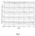
- the covariance matrix L is poorly conditioned because the Doppler spread B D is small compared to the clock rate 1 / T. Consequently, the eigenvalues ⁇ k have a very steep decay and vanish quickly.
- One of the contributions of the invention is to take advantage of these qualities of independence of the random variables e k and of rapid decrease of the eigenvalues ⁇ k to substantially reduce the complexity of the estimator of the discrete channel.
- the receiver has an incomplete knowledge of the characteristics of its local oscillator and those of the SPD S C ( f ) of the transmission channel.
- the SPD most unpredictable from the viewpoint of information theory [7] is a bounded support flat spectrum width equal to the Doppler spread B D.
- the eigenvectors b k are equal in this case to the restrictions on the support of the SSAD data stream [8] well defined.
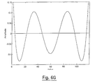
- the corresponding eigenvectors b k are also represented in FIGS. 6A to 6G.
- the PD of an embodiment c of the discrete channel at the level of a transmitted data stream is determined indirectly by the PD, p ( e ), of e which is of course well known to the receiver.
- the vector c can then be estimated according to the MAP criterion.
- the PDs of 2 N 0 and 2 E s ⁇ are generally unknown to the receiver. Their estimation is then generally accomplished according to the MV criterion.
- r (r 0, r 1, ..., r N-1) t
- a (a 0, a 1, ..., a N-1) t
- n (n 0 , n 1 , ..., n N-1 ) t the vectors of samples received, symbols transmitted and noise.
- some transmitted symbols are coded or fixed.
- the vector a of transmitted symbols is then characterized by the a priori discrete PD P ( a ).
- the MAP estimate ⁇ of c or equivalently, ê of e , is the value which maximizes the conditional PD a posteriori p ( e
- the iterative estimation (54) of e can be performed a finite number I of times. This number is chosen in such a way that the estimate e ( I ) reached is sufficiently close on average to the optimal estimate ê to guarantee an imperceptible degradation of the performance of the receiver.
- the weighting factors w m are also obtained in the case of the estimation of the discrete channel according to the least-squares method (MMC) with perfect knowledge of the transmitted data. They measure the quality of the contribution of a basic vector b m in the representation of the estimate to the MAP of the discrete channel.
- MMC least-squares method
- the coding structure can be integrated directly into the preceding formula.
- the value of the estimate of the channel towards which the EM algorithm converges is largely conditioned by the initial conditions used by this algorithm. If these initial conditions are poorly chosen, the EM algorithm can converge towards estimates, ê of e , corresponding to local maxima of the conditional PD a posteriori p ( e
- the choice of the location of these synchronization symbols in trains of transmitted data is not only decisive for the quality of the channel estimation but also for the good convergence of the EM algorithm towards the optimal estimation which maximizes p ( e
- the uniform distribution of the synchronization symbols at the level of the transmitted data streams is beneficial not only for a better estimation of the channel but also for a better stabilization and even an acceleration of the convergence of the algorithm EM.
- the EM algorithm has instabilities that can severely compromise the quality of the channel estimation.
- One of the contributions of the invention is to be able to stabilize this algorithm by taking into account part or all of the coded structure of the information symbols of the received data train.
- Simple codes such as repetitive codes whose code words are well interleaved at the level of the data streams can be advantageously used to accomplish this stabilization task at low cost.
- the detector or decoder 510 can be designed to minimize a given criterion. It can in particular minimize the probability of error of the information data or of the coded modulated symbols.
- This detector can take into account the memory of the phase modulation used or the coded structure of the symbols transmitted. This can be taken into account in particular via the Viterbi algorithm [11, 12], the Bahl algorithm [9] or the SOVA algorithm [10]. These last two algorithms can be used advantageously in the case where the receiver requires confidence values of the decoded data. This is particularly the case for communication systems using serial concatenated coding and where the external decoder needs weighted outputs of the internal code to improve its performance.
- the coding structure can be integrated directly into the preceding formula.
Landscapes
- Engineering & Computer Science (AREA)
- Computer Networks & Wireless Communication (AREA)
- Signal Processing (AREA)
- Power Engineering (AREA)
- Digital Transmission Methods That Use Modulated Carrier Waves (AREA)
- Mobile Radio Communication Systems (AREA)
Abstract
Description
Le domaine de l'invention est celui de la transmission de données numériques, en particulier dans des canaux de transmission présentant, ou pouvant présenter, des évanouissements à fort Doppler et de faibles interférences entre symboles (IES). Plus précisément, l'invention concerne l'estimation du canal de transmission et la démodulation dans des récepteurs de signaux transmis aux travers de tels canaux.The field of the invention is that of the transmission of digital data, in particular in transmission channels having, or which may have, high Doppler fading and low symbol interference (IES). More specifically, the invention relates to the estimation of the transmission channel and the demodulation in receivers of signals transmitted through such channels.
Un domaine d'application priviliégié, bien que non exclusif, de l'invention est celui des communications numériques entre des satellites et des mobiles. Elle peut être envisagée notamment dans le cadre des projets ICO et Iridium. Plus généralement, l'invention s'applique avantageusement dans tous les systèmes de communications où le canal présente un fort Doppler et une faible IES.A privileged, although not exclusive, field of application of the invention is that of digital communications between satellites and mobiles. It can be envisaged in particular within the framework of the ICO and Iridium projects. More generally, the invention advantageously applies in all communications systems where the channel has a high Doppler and a low IES.
Dans les systèmes de communications numériques conventionnels, on utilise fréquemment des symboles de synchronisation. Ils permettent au récepteur non seulement de se synchroniser, mais aussi d'estimer convenablement le canal pour garantir un bon déroulement de la phase de démodulation.In conventional digital communications systems, synchronization symbols are frequently used. They allow the receiver not only to synchronize, but also to properly estimate the channel to guarantee a good progress of the demodulation phase.
Dans le cas de ces systèmes de communication conventionnels, les symboles de synchronisation sont consécutifs et forment une séquence de synchronisation, généralement placée au début des trains de données. La synchronisation au niveau du récepteur est réalisée en détectant un dépassement de seuil de la corrélation des échantillons reçus avec ceux de la séquence utilisée pour la synchronisation. Cette synchronisation permet d'une part la détection du début d'un train de données et d'autre part la détermination avec précision des instants d'ouverture maximale du diagramme de l'oeil.In the case of these conventional communication systems, the synchronization symbols are consecutive and form a synchronization sequence, generally placed at the start of the data streams. Synchronization at the receiver is achieved by detecting that the correlation of the samples received with those of the sequence used for synchronization has exceeded the threshold. This synchronization allows on the one hand the detection of the start of a data train and on the other hand the determination with precision of the instants of maximum opening of the diagram of the eye.
Dans le cadre des études effectuées pour le système GSM, on a cherché à construire des séquences de synchronisation adaptées aux canaux à évanouissement à faible Doppler et à forte IES. Ces études ont montré l'intérêt, pour ce genre de canaux, de placer ces séquences de synchronisation au milieu de chaque train de données.In the framework of studies carried out for the GSM system, we sought to construct synchronization sequences adapted to low Doppler fading channels and to high IES. These studies have shown the interest, for this kind of channels, of placing these synchronization sequences in the middle of each data stream.
Les motifs de séquences de synchronisation proposés conduisent à des algorithmes de synchronisation et d'estimation de canal intuitifs et simples à mettre en oeuvre. Ils ont en conséquence été adoptés dans plusieurs systèmes de communications numériques.The proposed synchronization sequence patterns lead to intuitive and simple to implement synchronization and channel estimation algorithms artwork. They have therefore been adopted in several digital communications systems.
Ils sont également envisagés dans des projets de téléphonie par satellite. Toutefois, ils s'avèrent beaucoup moins efficaces pour ce type de canaux, et conduisent à des limitations importantes en terme de performance lorsqu'on aborde des canaux à fort Doppler et à faible IES, tels qu'un canal satellite.They are also envisaged in satellite telephony projects. However, they prove to be much less effective for this type of channel, and lead to significant limitations in terms of performance when tackling high Doppler and low IES channels, such as a satellite channel.
Le principe de base de la synchronisation temporelle et de l'estimation de canal par le récepteur est de transmettre une séquence de symboles connus de celui-ci dans les trains de données envoyées par l'émetteur. Moyennant l'utilisation de quelques algorithmes prédéfinis, ces symboles sont exploités pour garantir non seulement une bonne synchronisation du récepteur, mais aussi une estimation fiable du canal, permettant ainsi un bon déroulement de la phase de démodulation.The basic principle of time synchronization and channel estimation by the receiver is to transmit a sequence of symbols known to it by the data streams sent by the transmitter. By using a few predefined algorithms, these symbols are used to guarantee not only good synchronization of the receiver, but also a reliable estimate of the channel, thus allowing a good progress of the demodulation phase.
Dans les systèmes connus, on utilise un motif de synchronisation constitué d'une séquence de symboles groupés possédant de bonnes propriétés de corrélation. Ces propriétés sont mises à profit principalement pour bien se synchroniser au niveau du récepteur. Dans le cadre des systèmes de communications radio-mobiles, tels que le GSM, le canal est quasi statique durant un train de données mais présente cependant des IES très sévères. Ces propriétés de corrélation s'avèrent alors bien adaptées et même nécessaires à une estimation simple et directe de la réponse impultionnelle du canal.In known systems, a synchronization pattern is used which consists of a sequence of grouped symbols having good correlation properties. These properties are mainly used to synchronize well at the receiver. In the framework of radio-mobile communication systems, such as GSM, the channel is almost static during a data train but nevertheless presents very severe IES. These correlation properties then prove to be well suited and even necessary for a simple and direct estimation of the impultional response of the channel.
Ces séquences de synchronisation peuvent être utilisées dans des systèmes de communications entre satellites et mobiles. Il est cependant à noter que si les canaux rencontrés dans ce genre d'applications présentent des IES négligeables par rapport au rythme symbole, leurs variations au niveau des trains de données reçus sont très importantes. En d'autres termes, le canal de transmission ne peut alors pas être considéré comme quasi statique pendant la durée d'un train de données (en terme de représentation temps-fréquence, on peut dire que ces canaux sont les duaux de ceux présentés ci-dessus).These synchronization sequences can be used in communications systems between satellites and mobiles. It should however be noted that if the channels encountered in this type of application have negligible IES compared to the symbol rate, their variations in the level of the received data streams are very large. In other words, the transmission channel cannot then be considered as quasi-static during the duration of a data train (in terms of time-frequency representation, we can say that these channels are the dual of those presented here. -above).
De ce fait, l'utilisation d'une séquence de synchronisation classique dans ce type de systèmes est purement arbitraire, et ne résoud que le seul problème de synchronisation au niveau du récepteur.Therefore, the use of a classic synchronization sequence in this type of system is purely arbitrary, and only solves the only problem of synchronization at the receiver.
Plus précisément, si le choix de la synchronisation groupée dans le cadre des canaux quasi statiques à forte IES (cas classique du GSM notamment) est bien fondé, il n'en est pas nécessairement de même des canaux à fort Doppler et faible IES. Ces derniers présentent des variations considérables au niveau des trains de données reçus. La séquence de symboles de synchronisation classique peut garantir une bonne synchronisation du récepteur. En revanche, la qualité de l'estimation de canal est sévèrement compromise, car non représentative de l'état du canal pendant la réception des données utiles d'un train de données.More precisely, if the choice of group synchronization in the context of quasi-static channels with high IES (classic case of GSM in particular) is well founded, it is not necessarily the same for channels with high Doppler and low IES. These present considerable variations in the level of data trains received. The sequence of conventional synchronization symbols can guarantee good synchronization of the receiver. On the other hand, the quality of the channel estimation is severely compromised, since it is not representative of the state of the channel during the reception of the useful data from a data stream.
La synchronisation classique n'est donc pas adaptée aux systèmes communicant à travers un canal à fort Doppler, pour la fonction d'estimation du canal et de démodulation.Classic synchronization is therefore not suitable for systems communicating through a high Doppler channel, for the channel estimation and demodulation function.
L'invention a notamment pour objectif de pallier ces inconvénients de l'état de la technique, dans les systèmes de transmsission numérique organisés en trains de données, et pouvant être confrontés, au moins dans certaines situations et/ou à certains instants, à des canaux à fort Doppler, ne pouvant pas être considérés comme quasi statiques sur la durée d'un train de données.The invention particularly aims to overcome these drawbacks of the state of the art, in digital transmission systems organized in data trains, and which may be confronted, at least in certain situations and / or at certain times, with high Doppler channels, which cannot be considered as quasi-static over the duration of a data train.
Plus précisément, un des objectifs de l'invention est de fournir des structures de signaux numériques adaptées à la transmission dans des canaux à fort Doppler, et permettant notamment d'effectuer une estimation du canal et une démodulation fiables en toute circonstance.More specifically, one of the objectives of the invention is to provide digital signal structures suitable for transmission in high Doppler channels, and in particular making it possible to perform reliable channel estimation and demodulation in all circumstances.
Un autre objectif de l'invention est de fournir de tels signaux permettant d'optimiser simultanément, dans les récepteurs, la synchronisation, la qualité de l'estimation de canal et, le cas échéant, l'efficacité de l'entrelacement des données codées. En d'autres termes, il doit réaliser un compromis entre une bonne synchronisation, une bonne estimation du canal au niveau du récepteur et un bon entrelacement des données codées.Another objective of the invention is to provide such signals making it possible to simultaneously optimize, in the receivers, the synchronization, the quality of the channel estimation and, if necessary, the efficiency of the interleaving of the coded data. . In other words, it must achieve a compromise between good synchronization, good estimation of the channel at the receiver and good interleaving of the coded data.
L'invention a également pour objectif de fournir de tels signaux qui soient simples à construire, au niveau des émetteurs, et simples à décoder et à analyser dans les récepteurs. Un autre objectif de l'invention est également de limiter les pertes en débit utile, et donc de limiter le nombre de données de référence nécessaires.The invention also aims to provide such signals which are simple to construct, at the level of the transmitters, and simple to decode and analyze in the receivers. Another objective of the invention is also to limit the losses in useful throughput, and therefore limit the number of reference data required.
Un autre objectif de l'invention est de fournir des procédés d'estimation de canal, et des récepteurs correspondants, adaptés à de tels signaux et, plus généralement, qui puissent manipuler des motifs arbitraires de synchronisation.Another object of the invention is to provide methods of channel estimation, and corresponding receivers, adapted to such signals and, more generally, which can manipulate arbitrary synchronization patterns.
Un objectif complémentaire de l'invention est de fournir un estimateur de canal qui puisse améliorer significativement ses performances en tenant en compte de tout ou partie de la structure codée des données émises.An additional objective of the invention is to provide a channel estimator which can significantly improve its performance by taking into account all or part of the coded structure of the transmitted data.
Ces objectifs, ainsi que d'autres qui apparaîtront par la suite, sont atteints selon l'invention à l'aide de signaux numériques organisés en trains de données, dans chacun desquels au moins deux blocs d'éléments de référence distincts sont répartis parmi les données utiles.These objectives, as well as others which will appear subsequently, are achieved according to the invention using digital signals organized in data trains, in each of which at least two blocks of distinct reference elements are distributed among the useful data.
En d'autres termes, l'invention concerne notamment un signal numérique, organisé en trains de données consécutifs comprenant chacun un nombre prédéterminé de symboles successifs, et destiné à être transmis vers au moins un récepteur, dans un canal de transmission pouvant présenter des variations notables à l'intérieur d'un train de données, chacun desdits trains de données comportant au moins deux blocs distincts de référence pour l'estimation dudit canal, répartis parmi les symboles utiles représentatifs du signal source à transmettre, chacun desdits blocs de référence étant formé par au moins un symbole de référence (encore appelé parfois par la suite symbole de synchronisation, lorsqu'il est utilisé également pour la synchronisation) connu du récepteur et/ou identifiable par ledit récepteur.In other words, the invention relates in particular to a digital signal, organized in consecutive data streams each comprising a predetermined number of successive symbols, and intended to be transmitted to at least one receiver, in a transmission channel which may have variations. notable within a data stream, each of said data streams comprising at least two distinct reference blocks for estimating said channel, distributed among the useful symbols representative of the source signal to be transmitted, each of said reference blocks being formed by at least one reference symbol (also sometimes called subsequently synchronization symbol, when it is also used for synchronization) known to the receiver and / or identifiable by said receiver.
Le signal de l'invention présente donc une structure tout à fait différente de celle des signaux classiques, dans lesquels les symboles de référence, utilisés pour estimer le canal, sont systématiquement groupés en un bloc de synchronisation unique (généralement en début du train de données, ou éventuellement au milieu de celui-ci).The signal of the invention therefore has a structure quite different from that of conventional signals, in which the reference symbols, used to estimate the channel, are systematically grouped into a single synchronization block (generally at the start of the data stream , or possibly in the middle of it).
La solution de l'invention, qui va à l'encontre de cette technique classique, apporte une réponse efficace aux problèmes liés aux canaux à forts Doppler. Outre le fait que la structure du signal (répartition des blocs de référence) est tout à fait nouvelle, il est à noter qu'elle n'est nullement évidente pour l'homme du métier, notamment du fait qu'elle n'est pas compatible avec les méthodes conventionnelles d'estimation du canal et de décodage utilisant un bloc de référence unique. Comme on le verra par la suite, l'invention concerne également des procédés et des dispositifs nouveaux et spécifiques à l'utilisation de tels signaux.The solution of the invention, which goes against this conventional technique, provides an effective response to the problems associated with high Doppler channels. In addition to the fact that the structure of the signal (distribution of the reference blocks) is completely new, it should be noted that it is by no means obvious to those skilled in the art, in particular because it is not compatible with conventional methods channel estimation and decoding using a single reference block. As will be seen below, the invention also relates to new and specific methods and devices for the use of such signals.
Les symboles de référence présents dans les blocs de référence de l'invention peuvent être de deux types. Il peut s'agir de :
- symboles de référence explicite, fixés et connus a priori par ledit récepteur ; et/ou de
- symboles de référence implicite, produits par les liens générés entre les symboles utiles par un codage.
Selon un mode de réalisation particulier, ces symboles de référence implicite peuvent correspondre à la répétition d'un symbole utile, à un emplacement prédéterminé dans ledit train de données. Ces symboles de référence implicite sont donc obtenus dans ce cas à l'aide d'un code à répétition.
- explicit reference symbols, fixed and known a priori by said receiver; and / or
- implicit reference symbols, produced by links generated between useful symbols by coding.
According to a particular embodiment, these implicit reference symbols can correspond to the repetition of a useful symbol, at a predetermined location in said data stream. These implicit reference symbols are therefore obtained in this case using a repetitive code.
Lorsque le rendement souhaité pour l'application est compatible avec l'utilisation d'un codage, en particulier à répétition, on peut utiliser les deux types de symboles de référence, les symboles de référence implicite étant utilisés pour optimiser les informations obtenues à l'aide des symboles de référence explicite. Dans le cas où il n'y a que des symboles de référence implicite, il peut être nécessaire de prévoir un moyen pour lever l'ambiguïté de phase de la porteuse qui apparaît à la réception.When the desired performance for the application is compatible with the use of coding, in particular repetition, the two types of reference symbols can be used, the implicit reference symbols being used to optimize the information obtained from the using explicit reference symbols. In the case where there are only implicit reference symbols, it may be necessary to provide a means for removing the phase ambiguity of the carrier which appears on reception.
De façon préférentielle, lesdits blocs de référence sont équirépartis à l'intérieur du train de données.Preferably, said reference blocks are equally distributed within the data stream.
Comme mentionné plus haut, le signal de l'invention nécessite l'utilisation de procédés d'estimation nouveaux.As mentioned above, the signal of the invention requires the use of new estimation methods.
Ainsi, un premier procédé d'estimation d'un canal de transmission d'un tel signal numérique (organisé en trains de données consécutifs comportant au moins deux blocs distincts de référence pour l'estimation dudit canal, répartis parmi les symboles utiles représentatifs du signal source à transmettre, chacun desdits blocs de référence étant formé par au moins un symbole de référence connu du récepteur et/ou identifiable par ledit récepteur) met en oeuvre un algorithme d'Estimation-Maximisation (EM) [2-6] (les références numérotées ainsi sont regroupées dans une liste en annexe) comprenant les étapes suivantes, pour chacun desdits trains de données :
- extraction et/ou détermination desdits symboles de référence explicite ;
- utilisation desdits symboles de référence explicite, pour obtenir une première estimation dudit canal de transmission ;
- première estimation desdits symboles utiles, en fonction de ladite première estimation du canal de transmission ;
- détermination d'une seconde estimation, plus précise, dudit canal de transmission, en fonction de ladite première estimation des symboles utiles (pouvant comprendre notamment des symboles de référence implicite) ;
- seconde estimation desdits symboles utiles, en fonction de ladite seconde estimation du canal de transmission.
- extraction and / or determination of said explicit reference symbols;
- use of said explicit reference symbols to obtain a first estimate of said transmission channel;
- first estimate of said useful symbols, based on said first estimate of the transmission channel;
- determination of a second, more precise estimate of said transmission channel, as a function of said first estimate of useful symbols (which may notably include implicit reference symbols);
- second estimation of said useful symbols, as a function of said second estimation of the transmission channel.
Selon un mode de réalisation particulier, utilisable notamment lorsque le code mis en oeuvre est simple (ne nécessitant pas de calcul de probabilités, par exemple), ladite étape de seconde estimation desdits symboles utiles peut être intégrée dans ladite étape de détermination d'une seconde estimation du canal de transmission, l'estimation des symboles utiles étant utilisée directement dans le calcul de l'estimation du canal de transmission.According to a particular embodiment, usable in particular when the code implemented is simple (not requiring the calculation of probabilities, for example), said step of second estimation of said useful symbols can be integrated into said step of determining a second transmission channel estimation, the estimation of useful symbols being used directly in the calculation of the transmission channel estimation.
En d'autres termes, on effectue alors une estimation du canal avec estimation implicite des données.In other words, an estimation of the channel is then carried out with implicit estimation of the data.
Un second procédé d'estimation d'un canal de transmission d'un tel signal numérique comprend une étape d'écriture de ladite estimation sous la forme d'une combinaison de fonctions de base prédéterminées, de largeur de bande supérieure ou égale à celle du spectre de puissance Doppler (SPD) dudit signal.A second method for estimating a transmission channel of such a digital signal comprises a step of writing said estimate in the form of a combination of predetermined basic functions, with a bandwidth greater than or equal to that of the Doppler power spectrum (SPD) of said signal.
De façon préférentielle, lesdites fonctions de base sont des restrictions de séquences sphéroïdales aplaties discrètes (SSAD, connues dans la littérature anglaise sous le nom de « Discrete Prolate Spheroidal Sequences ») [8].Preferably, said basic functions are restrictions on discrete flattened spheroidal sequences (SSAD, known in the English literature under the name of "Discrete Prolate Spheroidal Sequences") [8].
Ce type de fonctions permet d'obtenir une estimation très précise du canal, à partir d'un nombre réduit de fonctions de base (par exemple 3 à 8).This type of function makes it possible to obtain a very precise estimate of the channel, from a reduced number of basic functions (for example 3 to 8).
Selon un mode de réalisation avantageux de l'invention, ce procédé comprend une étape préliminaire d'adaptation des caractéristiques desdites fonctions de base, notamment en fonction dudit spectre de puissance Doppler.According to an advantageous embodiment of the invention, this method comprises a preliminary step of adaptation of the characteristics of said basic functions, in particular as a function of said Doppler power spectrum.
On obtient ainsi une base adaptée au mieux au canal à estimer.A base is thus obtained which is best suited to the channel to be estimated.
L'invention concerne également, bien sûr, les dispositifs d'estimation de canal et les récepteurs mettant en oeuvre les procédés décrits ci-dessus, ainsi que les émetteurs et récepteurs de signaux selon l'invention.The invention also relates, of course, to the channel estimation devices and the receivers implementing the methods described above, as well as the signal transmitters and receivers according to the invention.
D'autres caractéristiques et avantages de l'invention apparaîtront à la lecture de la description suivante d'un mode de réalisation préférentiel de l'invention, donné à titre de simple exemple illustratif et non limitatif, et des dessins annexés, parmi lesquels :
- la figure 1 est un schéma synoptique d'un émetteur d'un signal selon l'invention ;
- la figure 2 est un schéma synoptique d'un récepteur selon l'invention, pouvant recevoir les signaux de l'invention ;
- la figure 3 illustre de façon schématique les principes de l'estimation du canal de transmission selon l'invention ;
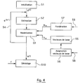
- la figure 4 présente le fonctionnement d'un récepteur mettant en oeuvre un procédé selon l'invention ;
- la figure 5 illustre la décroissance rapide des valeurs propres de la matrice de corrélation du canal discret au niveau des trains de données émis;
- les figures 6A à 6G illustrent les vecteurs propres correspondant aux valeurs propres les plus significatives de la matrice de corrélation du canal discret au niveau des trains de données émis ;
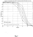
- la figure 7 illustre les pondérations des vecteurs propres, de la matrice de corrélation du canal discret au niveau des trains de données émis, utilisés dans l'estimation du canal par le récepteur.
- Figure 1 is a block diagram of a signal transmitter according to the invention;
- FIG. 2 is a block diagram of a receiver according to the invention, capable of receiving the signals of the invention;
- FIG. 3 schematically illustrates the principles of the estimation of the transmission channel according to the invention;
- Figure 4 shows the operation of a receiver implementing a method according to the invention;
- FIG. 5 illustrates the rapid decrease of the eigenvalues of the correlation matrix of the discrete channel at the level of the transmitted data streams;
- FIGS. 6A to 6G illustrate the eigenvectors corresponding to the most significant eigenvalues of the correlation matrix of the discrete channel at the level of the transmitted data streams;
- FIG. 7 illustrates the weightings of the eigenvectors, of the correlation matrix of the discrete channel at the level of the transmitted data streams, used in the estimation of the channel by the receiver.
L'invention s'applique donc notamment à des canaux stationnaires à faible IES avec des SPD de largeurs et formes quelconques. En particulier, ces canaux peuvent être de type Rice ou Rayleigh avec des SPD en corne ou plats. Notamment, ils peuvent inclure le cas d'un décalage (« offset ») statique en fréquence résultant d'une correction partielle de l'erreur de fréquence de l'oscillateur local au niveau du récepteur. Cette correction est en général accomplie grâce à une boucle à verrouillage de phase conventionnelle.The invention therefore applies in particular to stationary channels with low IES with SPDs of any width and shape. In particular, these channels can be of the Rice or Rayleigh type with horn or flat SPDs. In particular, they can include the case of a frequency offset resulting from a partial correction of the frequency error of the local oscillator at the level of the receiver. This correction is generally accomplished by a conventional phase locked loop.
L'invention propose une structure de signal nouvelle, dans laquelle plusieurs blocs de référence sont répartis dans chaque train de données.The invention provides a new signal structure, in which several reference blocks are distributed in each data stream.
Ainsi, un objectif de l'invention est de fournir pour un canal Doppler et un système de communication de caractéristiques données le motif de synchronisation le mieux adapté. Ce motif doit être suffisamment réparti sur une partie plus au moins étendue des trains de données pour caractériser et estimer au mieux les variations significatives du canal et répartir au mieux les données codées. Il ne doit donc pas privilégier les performances du récepteur en terme de synchronisation au prix du sacrifice de la qualité de l'estimation de canal et de l'entrelacement des données codées.Thus, an objective of the invention is to provide for a Doppler channel and a communication system of given characteristics the most suitable synchronization pattern. This pattern must be sufficiently distributed over a more or less extensive part of the data streams to characterize and estimate as well as possible the significant variations of the channel and distribute the coded data as well as possible. It should therefore not favor the performance of the receiver in terms of synchronization at the cost of sacrificing the quality of the channel estimation and the interleaving of the coded data.
Le procédé d'estimation de canal correspondant proposé selon l'invention repose notamment sur une modélisation convenable du canal réel et une représentation nouvelle et simplifiée de celle-ci.The corresponding channel estimation method proposed according to the invention is based in particular on a suitable modeling of the real channel and a new and simplified representation thereof.
Cette représentation doit tenir compte autant que possible de toutes les informations connues sur le canal. Ces informations doivent inclure au minimum la largeur maximale de la bande Doppler, qui doit être impérativement connue par le récepteur.This representation must take into account as much as possible all the information known on the channel. This information must include at least the maximum width of the Doppler band, which must be known to the receiver.
Dans le cas où la forme du SPD du canal n'est pas connue, l'algorithme adopte une modélisation plate de celle-ci. Cette modélisation convient le mieux du point de vue de la théorie de l'information car elle conduit à une entropie maximale de canal [7]. Dans ce cas précis, le canal discret peut s'écrire comme une combinaison des restrictions de séquences sphéroïdales aplaties discrètes (SSAD) au support du train de données à démoduler. Ces SSAD ont une bande étroite de largeur égale ou supérieure à celle du SPD.In the case where the shape of the SPD of the channel is not known, the algorithm adopts a flat modeling of this one. This modeling is best suited from the point of view of information theory because it leads to a maximum channel entropy [7]. In this case, the discrete channel can be written as a combination of the restrictions on discrete flattened spheroidal sequences (SSAD) on the support of the data stream to be demodulated. These SSADs have a narrow band of width equal to or greater than that of the SPD.
Il existe essentiellement deux critères qui peuvent être utilisés pour estimer un des paramètres inconnus : le critère du maximum de vraisemblance (MV) et le critère du maximum a posteriori (MAP) [1]. Dans le cas du critère MV, les paramètres sont supposés déterministes mais inconnus. Dans le cas du critère MAP, ces paramètres sont supposés aléatoires et caractérisés par une densité de probabilité (DP) a priori connue.There are essentially two criteria which can be used to estimate one of the unknown parameters: the maximum likelihood criterion (MV) and the posterior maximum criterion (MAP) [1]. In the case of the MV criterion, the parameters are assumed to be deterministic but unknown. In the case of the MAP criterion, these parameters are assumed to be random and characterized by an a priori known probability density (PD).
Le critère MV convient le mieux aux problèmes d'estimation de l'énergie par symbole émis ou de la variance de bruit à la sortie d'un filtre donné, quand ceux-ci ne sont pas connus par le récepteur. Le critère MAP convient le mieux au problème d'estimation du canal discret au niveau des trains de données émis.The criterion MV is best suited to the problems of estimating the energy per symbol emitted or the variance of noise at the output of a given filter, when these are not known by the receiver. The MAP criterion is best suited to the problem of estimating the discrete channel at the level of transmitted data streams.
Moyennant la représentation simplifiée du canal développée par les inventeurs et présentée par la suite, et (non obligatoirement) les symboles de référence envoyés par l'émetteur, le récepteur met en oeuvre l'algorithme EM pour effectuer une estimation itérative d'une partie ou de la totalité de ces paramètres selon les critères correspondants.By means of the simplified representation of the channel developed by the inventors and presented subsequently, and (not necessarily) the reference symbols sent by the transmitter, the receiver implements the EM algorithm to perform an iterative estimation of a part or of all of these parameters according to the corresponding criteria.
Autrement dit, cet algorithme permet de retrouver la réalisation de canal la plus vraisemblable conditionnellement au signal observé au niveau du récepteur. Il permet également d'estimer au mieux l'énergie par symbole transmis et/ou de la variance de bruit à la sortie d'un filtre donné quand ceux-ci ne sont pas totalement connus.In other words, this algorithm makes it possible to find the most likely channel realization conditionally on the signal observed at the receiver. It also makes it possible to best estimate the energy per symbol transmitted and / or the noise variance at the output of a given filter when these are not fully known.
L'un des avantages de l'algorithme EM est de pouvoir utiliser d'une façon optimale aussi bien des symboles de synchronisation (référence explicite) que la totalité ou une partie des caractéristiques des symboles d'information (référence implicite) composant un train de données pour accomplir l'estimation de canal. Plus précisément, cet algorithme permet d'utiliser avantageusement le codage subi par les données d'informations envoyées pour améliorer significativement la qualité de l'estimation de canal. Il permet également de tenir compte de la mémoire éventuellement due à la modulation utilisée.One of the advantages of the EM algorithm is that it can optimally use both synchronization symbols (explicit reference) and all or part of the characteristics of the information symbols (implicit reference) making up a train of data to complete channel estimation. More precisely, this algorithm makes it possible to advantageously use the coding undergone by the information data sent to significantly improve the quality of the channel estimation. It also makes it possible to take account of the memory possibly due to the modulation used.
Cet algorithme évite de recourir systématiquement aux motifs de synchronisation groupés classiques, qui doivent leur succès à leur exploitation immédiate par des algorithmes intuitifs et simples.This algorithm avoids the systematic use of classic grouped synchronization patterns, which owe their success to their exploitation immediate by intuitive and simple algorithms.
Le choix de l'emplacement des symboles de référence dans les trains de données est en effet important pour les performances de l'estimateur de canal. Il est également d'importance capitale dans la bonne détermination des conditions initiales de l'algorithme EM. En effet, celui-ci tend en général à converger vers des maxima locaux de la probabilité conditionnelle (défini comme la probabilité a posteriori d'une réalisation du canal conditionnellement au signal reçu), si l'emplacement des symboles de synchronisation est mal choisi.The choice of the location of the reference symbols in the data streams is indeed important for the performance of the channel estimator. It is also of capital importance in the correct determination of the initial conditions of the EM algorithm. Indeed, this generally tends to converge towards local maxima of the conditional probability (defined as the posterior probability of a realization of the channel conditionally on the received signal), if the location of the synchronization symbols is poorly chosen.
A l'aide de l'estimation du canal, le récepteur effectue d'une manière standard une démodulation et/ou un décodage des données d'information reçues selon le critère du MV.With the aid of the channel estimation, the receiver performs in a standard manner a demodulation and / or a decoding of the information data received according to the criterion of the MV.
La Figure 1 présente un schéma synoptique simplifié d'un émetteur d'un signal formé de train de données selon l'invention. Le procédé d'émission s'en déduit directement.Figure 1 shows a simplified block diagram of a transmitter of a data train signal according to the invention. The emission process is directly deduced therefrom.
On considère une source d'information 11 de débit arbitraire générant des données binaires ou non correspondant à des signaux source de type quelconque (sons, images, données,... ). Ces données sont éventuellement soumises à un codage de source 12, suivi d'un codage correcteur d'erreurs 13 adapté aux canaux de type Rice sans IES.We consider an
Les données codées générées à partir de ces codes (symboles utiles) sont ensuite organisées en trains de données et modulées (14). Elles sont donc convenablement réparties et entrelacées sur plusieurs trains de données afin d'apporter la diversité nécessaire et de décorréler l'évanouissement affectant les symboles transmis. Des éléments de référence sont également introduits dans chaque train de données, selon les principes de répartition précisés par la suite. Enfin, les données sont modulées en phase.The coded data generated from these codes (useful symbols) are then organized into data streams and modulated (14). They are therefore suitably distributed and interleaved on several data streams in order to provide the necessary diversity and to decorrelate the fading affecting the symbols transmitted. Reference elements are also introduced into each data stream, according to the distribution principles specified below. Finally, the data is modulated in phase.
Le signal en bande de base généré par le modulateur 14 est obtenu par filtrage de mise en forme des symboles composant ce train. Dans le cas des modulations MDP2 et MDP4, le filtre de mise en forme est en général un filtre en racine de Nyquist pour éviter toute IES en sortie du filtre adapté du récepteur. Le signal en bande de base ainsi généré est alors transposé en fréquence, amplifié et émis (15) à travers le canal.The baseband signal generated by the
A titre d'exemple, on présente ici les caractéristiques en émission du système ICO (Intermediate Circular Orbit) de radio-communication par satellite, auquel s'applique avantageusement l'invention.By way of example, the transmission characteristics of the ICO (Intermediate Circular Orbit) system of satellite radio communication are presented here, to which the invention advantageously applies.
Ce système est basé sur une technique d'accès multiple réparti dans le temps (AMRT). Il est basé sur des trames de données, composées chacune de 6 intervalles de temps (connues en anglais sous le nom de « time slots »). Ces trames sont émises dans les sens montant (mobile-satellite) et descendant (satellite-mobile) aussi bien pour les canaux dédiés à la voix que ceux dédiés à la signalisation. A chaque intervalle de temps correspond un train de données émis composé de N = 120 ou 240 symboles, selon les cas.This system is based on a time distributed multiple access technique (TDMA). It is based on data frames, each composed of 6 time slots (known in English as "time slots"). These frames are transmitted in the uplink (mobile-satellite) and downlink (satellite-mobile) directions for both voice and signaling channels. Each time interval corresponds to a transmitted data stream composed of N = 120 or 240 symbols, depending on the case.
L'ensemble des canaux logiques utilisés par le système ICO est très proche de celui du GSM. Il comporte, en particulier, un canal TCH (« Traffic CHannel ») au niveau des liaisons montante et descendante, un canal BCCH (« Broadcast Common Channel ») au niveau de la liaison descendante et un canal RACH (« Random Access Channel ») au niveau de la liaison montante.The set of logical channels used by the ICO system is very close to that of GSM. It comprises, in particular, a TCH channel (“Traffic CHannel”) at the level of the uplink and downlink, a BCCH channel (“Broadcast Common Channel”) at the level of the downlink and a RACH channel (“Random Access Channel”) at the uplink.
La modulation adoptée pour la liaison descendante est la MDP4 pour le TCH et la MDP2 pour le BCCH. Dans ces deux cas, le nombre de symboles par trains de données est de 120 (1 bit par symbole en MDP2 ; 2 bits par symbole en MDP4). La modulation GMSK à phase continue, et donc avec mémoire, est retenue au niveau de la liaison montante, pour des raisons de non-linéarité au niveau des émetteurs mobiles. Le nombre de symboles transmis est 240 pour le TCH, et 120 pour le RACH. Dans les deux cas, un symbole émis correspond à un bit émis.The modulation adopted for the downlink is MDP4 for TCH and MDP2 for BCCH. In these two cases, the number of symbols per data stream is 120 (1 bit per symbol in MDP2; 2 bits per symbol in MDP4). The GMSK modulation with continuous phase, and therefore with memory, is retained at the level of the uplink, for reasons of non-linearity at the level of the mobile transmitters. The number of symbols transmitted is 240 for the TCH, and 120 for the RACH. In both cases, a transmitted symbol corresponds to a transmitted bit.
Chaque canal logique possède ses propres techniques de codage de canal et d'entrelacement. Cependant, ce codage et cet entrelacement sont organisés de façon à permettre, autant que possible, d'unifier la structure du décodeur. Chaque canal logique peut mettre en oeuvre la séquence d'opérations suivante (chacune de ces opérations étant optionnelle) :
- les éléments binaires d'information sont codés avec un code externe en bloc cyclique et systématique ;
- les élément binaires résultant de ce codage sont ensuite codés par le code interne, soit de type Golay étendu, soit de type convolutif;
- les éléments binaires codés sont ensuite codés à l'aide d'un code à répétition;
- les éléments binaires codés obtenus sont finalement entrelacés avec une fonction d'entrelacement.
- the bits of information are coded with an external code in a cyclic and systematic block;
- the binary elements resulting from this coding are then coded by the internal code, either of extended Golay type, or of convolutional type;
- the coded bits are then coded using a repeating code;
- the coded bits obtained are finally interleaved with an interleaving function.
Le canal RACH véhicule entre autres l'identité d'un terminal mobile qui veut accéder aux services du système ICO. Il nécessite une marge de liaison plus importante que les canaux de trafic. Pour cette raison, il met en oeuvre un code de Golay suivi d'un code à répétition (3,13) .Among other things, the RACH channel conveys the identity of a mobile terminal that wants to access the services of the ICO system. It requires a higher link margin than traffic channels. For this reason, it implements a Golay code followed by a repetitive code (3.13).
Selon l'invention, les symboles de référence sont répartis dans plusieurs blocs (d'au moins un symbole) dans chaque train de données.According to the invention, the reference symbols are distributed in several blocks (of at least one symbol) in each data stream.
Le nombre de symboles utilisés pour la synchronisation dépend des caractéristiques du canal de transmission réel.The number of symbols used for synchronization depends on the characteristics of the actual transmission channel.
Le canal de transmission sous-jacent au canal logique TCH est un canal de type Rice (c'est-à-dire constitué d'un trajet direct et d'une partie multi-trajets avec un retard relatif quasi nul par rapport à ce dernier) présentant un rapport K entre la puissance du trajet direct et celle des multi-trajets favorable, avec des valeurs de l'ordre de 7 à 12 dB. Le canal TCH peut utiliser en tant que références seulement 10% des symboles du train de données, soit 12 symboles de référence par train de données émis pour la liaison descendante, et 24 symboles de référence par train de données émis pour la liaison montante.The transmission channel underlying the TCH logical channel is a Rice type channel (that is to say consisting of a direct path and a multi-path part with a relative delay almost zero relative to the latter. ) presenting a ratio K between the power of the direct path and that of the multipath favorable, with values of the order of 7 to 12 dB. The TCH channel can use as references only 10% of the symbols of the data stream, that is to say 12 reference symbols per data stream transmitted for the downlink, and 24 reference symbols per data stream transmitted for the uplink.
Ces symboles peuvent être uniformément répartis, un par un, deux par deux ou quatre par quatre sur tout un train de données (blocs de référence comprenant 1, 2, ou 4 symboles de référence).These symbols can be uniformly distributed, one by one, two by two or four by four over an entire data stream (reference blocks comprising 1, 2, or 4 reference symbols).
Pour un meilleur calcul des conditions initiales pour l'estimation du canal discret, il est conseillé de mettre en oeuvre l'une des deux premières formes de synchronisation pour la liaison descendante.For a better calculation of the initial conditions for the estimation of the discrete channel, it is advised to implement one of the first two forms of synchronization for the downlink.
La Table 1 illustre un mode d'implantation dans lequel les blocs de référence comprennent 2 symboles de référence. Cette implantation est utilisé pour le canal TCH de la liaison descendante.
Pour la liaison montante, la troisième forme (table 2) est la plus adaptée, car elle permet de s'affranchir à moindres coûts de la mémoire de la modulation GMSK dans le choix des conditions initiales. Dans ce cas particulier, seule une partie de la forme d'onde correspondant au blocs de quatre symboles de référence est utilisée pour le calcul de ces conditions initiales.
Le canal logique BCCH est en particulier utilisé par les terminaux mobiles pour effectuer la synchronisation au niveau des trains de données. Le canal de transmission réel sous-jacent est de type Rice avec une valeur de K de l'ordre de 0 dB. Pour ces deux raisons, 32 symboles de référence explicite sont prévus.The BCCH logical channel is in particular used by mobile terminals to perform synchronization at the level of data trains. The underlying real transmission channel is of the Rice type with a value of K of the order of 0 dB. For these two reasons, 32 explicit reference symbols are provided.
La table 3 illustre la structure correspondante du train de données.
Une partie de ces symboles (mot de synchronisation) peut alors être groupée au milieu du train de données pour garder des performances acceptables en terme de synchronisation et de détermination de l'ouverture maximale du diagramme de l'oeil, au niveau du récepteur. L'autre partie est alors répartie sur le reste du train de données, comme c'est le cas pour le canal logique TCH.A part of these symbols (synchronization word) can then be grouped in the middle of the data stream to keep acceptable performance in terms of synchronization and determination of the maximum opening of the eye diagram, at the level of the receiver. The other part is then distributed over the rest of the data stream, as is the case for the logical channel TCH.
Le canal logique RACH est utilisé dans la liaison montante par les terminaux mobiles pour demander l'accès aux services du système ICO. Le canal de transmission réel sous-jacent est en général du même type que celui du BCCH. Contrairement au canal BCCH, qui est répétitif, le canal RACH est émis de façon isolée, et doit donc être détecté en une seule passe. Par conséquent, le nombre de symboles de référence est 44, (au lieu de 32 pour le BCCH), ainsi que cela est précisé dans la table 4.
Comme dans le cas du canal logique BCCH, une partie de ces symboles de référence peut être groupée afin de former des références de synchronisation (2 blocs de 16 symboles). Cependant, comme la modulation GMSK utilisée est une modulation à mémoire, les symboles de référence restants doivent aussi être regroupés avant d'être répartis sur le reste du train. Ce regroupement (deux blocs de 6 symboles de référence) permet bien entendu au récepteur de s'affranchir temporairement de la mémoire de la modulation pour calculer les conditions initiales de l'algorithme itératif d'estimation de canal.As in the case of the BCCH logical channel, a part of these reference symbols can be grouped in order to form synchronization references (2 blocks of 16 symbols). However, since the GMSK modulation used is a memory modulation, the remaining reference symbols must also be grouped before being distributed over the rest of the train. This grouping (two blocks of 6 reference symbols) naturally allows the receiver to temporarily free itself from the modulation memory to calculate the initial conditions of the iterative channel estimation algorithm.
Dans cette situation, il y a donc quatre blocs de référence formés de 6 ou 16 symboles de référence explicite, et trois blocs formés de 24 symboles de référence implicites, correspondant à la répétition des mêmes symboles utiles.In this situation, there are therefore four reference blocks formed of 6 or 16 explicit reference symbols, and three blocks formed of 24 implicit reference symbols, corresponding to the repetition of the same useful symbols.
On réalise donc un compromis avantageux entre :
- la présence de blocs de référence relativement longs (6 ou 16 symboles), facilitant la synchronisation ;
- l'entrelacement du code à répétition (3 blocs répartis sur le train de données) ;
- le nombre de blocs répartis (4 + 3) pour l'estimation du canal.
- the presence of relatively long reference blocks (6 or 16 symbols), facilitating synchronization;
- interleaving the code repeatedly (3 blocks distributed over the data stream);
- the number of blocks distributed (4 + 3) for the estimation of the channel.
Comme cela a déjà été indiqué, la présence de symboles de référence explicite n'est pas obligatoire, bien qu'elle permette de simplifier les traitements. Des symboles de référence implicite seuls, obtenus par répétition, peuvent également être utilisés. Par ailleurs, on rappelle que l'utilisation d'un code à répétition n'est qu'un mode de réalisation avantageux, par sa simplicité, pour l'obtention des symboles de référence implicite. En effet, ces derniers peuvent être obtenus quel que soit le code utilisé, en analysant les liens générés entre les symboles utiles par ce code [6, 9].As already indicated, the presence of explicit reference symbols is not compulsory, although it simplifies the processing. Symbols implicit reference only, obtained by repetition, can also be used. Furthermore, it is recalled that the use of a repetitive code is only an advantageous embodiment, by its simplicity, for obtaining the implicit reference symbols. Indeed, these can be obtained whatever the code used, by analyzing the links generated between the symbols useful by this code [6, 9].
Lorsque les deux types de symboles de référence sont présents, les symboles de référence implicite sont avantageusement utilisés pour affiner l'estimation du canal.When the two types of reference symbols are present, the implicit reference symbols are advantageously used to refine the estimation of the channel.
La Figure 2 illustre un exemple de récepteur d'un signal selon l'invention ainsi que le procédé de réception correspondant.Figure 2 illustrates an example of a signal receiver according to the invention as well as the corresponding reception method.
Le signal correspondant à un train de données reçu est préamplifié 31, puis converti en fréquence intermédiaire 32 afin de réaliser le filtrage adapté de canal 33. Le signal en fréquence intermédiaire est ensuite converti en bande de base 34 sur deux voies en quadrature, ou sur une seule voie en fréquence intermédiaire basse, puis échantillonné (37).The signal corresponding to a received data stream is preamplified 31, then converted to
Le signal échantillonné est ensuite démodulé (39). Par ailleurs, il alimente un module de synchronisation 36 et un module d'estimation du canal de transmission 38.The sampled signal is then demodulated (39). Furthermore, it supplies a
Le module de synchronisation 36 utilise la séquence de synchronisation pour estimer le rythme symbole ainsi que les instants correspondant à l'ouverture maximale du digramme de l'oeil du signal en bande de basé reçu. Le signal est échantillonné (37) à ces instants précis.The
Les échantillons correspondant à un train de données sont par ailleurs utilisés par le récepteur pour déterminer une estimation 38 selon le critère MAP de la réalisation du canal discret au niveau de ceux-ci. Cette estimation 38 est effectuée moyennant la représentation simplifiée du canal discret au niveau du train de données reçu, l'utilisation de l'algorithme EM et éventuellement d'un algorithme tel que celui de Bahl [9].The samples corresponding to a data stream are also used by the receiver to determine an
Cet algorithme itératif, décrit par la suite, démarre à partir de conditions initiales arbitraires qui peuvent être obtenues avantageusement grâce aux symboles de synchronisation connus du récepteur.This iterative algorithm, described below, starts from arbitrary initial conditions which can be advantageously obtained thanks to the synchronization symbols known to the receiver.
La synchronisation répartie sur tout le train de données selon l'invention se révèle être d'une grande utilité parce qu'elle permet non seulement d'éviter la convergence de l'algorithme vers des maxima locaux de la probabilité conditionnnelle, mais aussi d'accélérer cette convergence à moindres frais.Synchronization distributed over the entire data train according to the invention proves to be of great utility because it makes it possible not only to avoid convergence of the algorithm towards local maxima of the conditional probability, but also to accelerate this convergence at lower cost.
Le récepteur utilise alors l'estimation 38 au MAP du canal discret au niveau d'un train de données reçu pour démoduler 39 selon un critère donné les symboles porteurs d'information de ce train. Le démodulateur 39 peut en particulier fournir des sorties pondérées afin d'améliorer les performances du décodeur 310.The receiver then uses the
Ces sorties, pondérées ou non, sont tout d'abord désentrelacées 311 et regroupées conformément à l'entrelacement et la répartition effectués au niveau de l'émetteur, puis décodées par le décodeur de canal 310. Les données démodulées sont ensuite décodées par le décodeur source 312, afin de fournir une estimation du signal source émis.These outputs, weighted or not, are first of all deinterleaved 311 and grouped in accordance with the interleaving and the distribution carried out at the level of the transmitter, then decoded by the
L'estimation de canal est également exploité par le récepteur pour contrôler le déroulement de la préamplification 31, moyennant l'utilisation d'une fonction de correction automatique de gain (CAG) 35.The channel estimation is also used by the receiver to control the progress of the
A titre d'exemple, et en relation avec la figure 3, on présente dans la suite quelques unes des caractéristiques du récepteur du système ICO dont l'émetteur est présenté dans la section précédente. Au niveau des terminaux mobiles, la synchronisation 41 des trains de données est effectuée d'une manière grossière 411, dans un premier temps, grâce à la détection du profil de puissance sur le canal logique BCCH.By way of example, and in relation to FIG. 3, some of the characteristics of the receiver of the ICO system whose transmitter is presented in the previous section are presented below. At the mobile terminals, the
Cette synchronisation est ensuite affinée 412 moyennant l'utilisation des symboles de synchronisation des trains de données du canal BCCH.This synchronization is then refined 412 by means of the symbols for synchronizing the data trains of the BCCH channel.
Au niveau du segment spatial (formé, dans le cas du système ICO, par l'ensemble des satellites et des stations terrestres, chaque satellite jouant uniquement un rôle de répéteur), les synchronisations grossière 411 et fine 412 sont accomplies de la même façon que par les terminaux mobiles en utilisant le canal logique RACH.At the level of the space segment (formed, in the case of the ICO system, by all of the satellites and the earth stations, each satellite playing only a repeater role), the coarse 411 and fine 412 synchronizations are accomplished in the same way as by mobile terminals using the RACH logical channel.
Au niveau des terminaux mobiles et des segments spatiaux, l'estimation 421, 422 du canal discret au niveau d'un train de données reçu est réalisée selon le critère du MAP. Cette estimation est réalisée grâce à l'algorithme décrit par la suite. Le récepteur commence dans un premier temps par utiliser les symboles de synchronisation pour établir des conditions initiales convenables 421 pour le bon fonctionnement de l'algorithme itératif.At the level of mobile terminals and space segments, the
A cette étape, il n'a aucune idée même partielle sur les valeurs probablement prises par les symboles d'information codés. Il attribue alors à ces symboles d'information des probabilités conditionnelles uniformes à entropie maximale 431 (selon le procédé décrit plus précisément par la suite).At this stage, he has no idea, even partial, of the values probably taken by the coded information symbols. It then attributes to these information symbols uniform conditional probabilities with maximum entropy 431 (according to the method described more precisely below).
Au niveau des liaisons descendantes, la symétrie des constellations de la MDP2 pour le BCCH et de la MDP4 pour le TCH conduit alors à une contribution nulle des symboles d'information dans le calcul des conditions initiales de l'algorithme itératif 44 d'estimation de canal. Ces conditions initiales sont ensuite utilisées par cet algorithme pour améliorer l'estimation du canal 422 en tenant cette fois-ci compte de la contribution supplémentaire 432 des symboles d'information codés.At the level of the downlinks, the symmetry of the constellations of the MDP2 for the BCCH and of the MDP4 for the TCH then leads to a zero contribution of the information symbols in the calculation of the initial conditions of the
Au niveau des liaisons montantes, l'estimation de canal au niveau des canaux logiques RACH et TCH suit à peut près les mêmes procédures que dans le cas des terminaux mobiles. La seule différence ici est que la modulation GMSK utilisée dans la liaison montante est une modulation à mémoire.At the uplink level, the channel estimation at the RACH and TCH logical channels follows roughly the same procedures as in the case of mobile terminals. The only difference here is that the GMSK modulation used in the uplink is a memory modulation.
Comme les symboles de synchronisation émis par les mobiles sont groupés sur une base d'au moins quatre par quatre symboles (dans le cas du TCH), l'IES dû à la mémoire de la modulation et aux symboles adjacents non connus n'affectent pas les symboles du milieu de chaque groupement. Ces symboles du milieu de chaque groupement peuvent alors être utilisés pour calculer les conditions initiales de l'algorithme itératif. Pour les itérations suivantes, l'algorithme itératif utilise alors le treillis de modulation de la GMSK pour tenir également compte des symboles de synchronisation restants et des symboles d'information codés (par exemple à l'aide de l'algorithme de Bahl).As the synchronization symbols transmitted by the mobiles are grouped on the basis of at least four by four symbols (in the case of TCH), the IES due to the modulation memory and to the adjacent symbols not known does not affect the symbols in the middle of each grouping. These symbols in the middle of each grouping can then be used to calculate the initial conditions of the iterative algorithm. For the following iterations, the iterative algorithm then uses the GMSK modulation trellis to also take into account the remaining synchronization symbols and coded information symbols (for example using the Bahl algorithm).
Dans le cas particulier du canal RACH, la réception des trains de données par le segment spatial, se fait d'une manière quasi asynchrone. Par ailleurs, on utilise les références implicites correspondant aux 3 blocs de 24 symboles obtenus par la répétition d'un code de Golay. Cette caractéristique de l'invention permet d'améliorer fortement la qualité de l'estimation du canal, tout en conservant également une bonne qualité de synchronisation, grâce aux références explicites groupées.In the particular case of the RACH channel, the reception of data trains by the space segment is done in an almost asynchronous manner. In addition, we use the implicit references corresponding to the 3 blocks of 24 symbols obtained by the repetition of a Golay code. This characteristic of the invention makes it possible to greatly improve the quality of the estimation of the channel, while also retaining a good quality of synchronization, thanks to the grouped explicit references.
La position choisie pour les symboles de référence implicite permet d'obtenir un bon entrelacement des mots du code à répétition (3,1,3). Comme la prise en compte du code à répétition (3,1,3) peut être intégrée directement dans l'algorithme d'estimation (dans le cas où la mémoire de modulation peut être négligée au premier ordre), elle engendre une augmentation imperceptible de la complexité de celui-ci.The position chosen for the implicit reference symbols makes it possible to obtain a good interlacing of the words of the code with repetition (3,1,3). As the consideration of the repetitive code (3,1,3) can be integrated directly into the estimation algorithm (in the case where the modulation memory can be neglected at the first order), it generates an imperceptible increase in the complexity of it.
Un des aspects de l'invention repose sur une modélisation et une représentation nouvelle simplifiée du canal discret vu à la sortie du filtre adapté du récepteur au niveau des trains de données envoyées.One aspect of the invention is based on a new simplified modeling and representation of the discrete channel seen at the output of the adapted filter of the receiver at the level of the sent data streams.
Le canal de transmission est supposé de type Rice. Il est constitué d'un trajet direct et d'une partie multi-trajets avec un retard relatif quasi nul par rapport à ce dernier. Le trajet direct est spécifié par un facteur d'atténuation complexe constant. La partie multi-trajets résultant de réflexions de terrain est quant à elle caractérisée comme un processus aléatoire stationnaire gaussien de moyenne nulle [1, 16].The transmission channel is assumed to be of the Rice type. It consists of a direct path and a multi-path part with an almost zero relative delay with respect to the latter. The direct path is specified by a constant complex attenuation factor. The multipath part resulting from field reflections is characterized as a stationary Gaussian random process with zero mean [1, 16].
Ce canal est caractérisé principalement par deux paramètres. Le premier est le rapport, K, entre la puissance du trajet direct et celle des multi-trajets. Le second paramètre est la fonction SPD de canal S C (f).This channel is mainly characterized by two parameters. The first is the ratio, K , between the power of the direct path and that of multi-paths. The second parameter is the SPD function of channel S C ( f ).
Cette fonction est un spectre de puissance qui donne l'intensité du canal de transmission en fonction de la fréquence Doppler f . Elle est égale à la transformée de Fourier de la fonction d'autocorrélation φ C (τ) du canal. Elle possède un support borné de largeur B D appelé étendue Doppler du canal. Dans le cadre de l'invention, cette étendue est supposée faible devant le rythme symbole 1/ T .This function is a power spectrum which gives the intensity of the transmission channel as a function of the Doppler frequency f. It is equal to the Fourier transform of the autocorrelation function φ C (τ) of the channel. It has a bounded support of width B D called Doppler extent of the channel. In the context of the invention, this extent is assumed to be small compared to the
L'invention peut s'appliquer à de nombreux types de modulation. Dans le cadre des communications par satellites, elle concerne particulièrement la réception de trains de données modulées en phase. Ceci inclut aussi bien les modulations conventionnelles (MDP2, MDP4, MDP8, MDP16, ...) que les modulations présentant une mémoire telles que les modulations à phase continue (MSK, GMSK,...).The invention can be applied to many types of modulation. In the context of satellite communications, it particularly concerns the reception of trains of phase modulated data. This includes both conventional modulations (MDP2, MDP4, MDP8, MDP16, ...) as well as modulations with memory such as continuous phase modulations (MSK, GMSK, ...).
Le signal en bande de base correspondant à un train de données émis de N symboles s'écrit, dans le cas d'une modulation MDP, sous la forme (aisément adaptable à d'autres types de modulation [1]):![]()
![]()
Le signal à l'entrée du récepteur correspond au signal en bande base émis distordu par le canal et corrompu par un bruit complexe additif blanc gaussien de puissance spectrale en bande de base 2N 0.The signal at the input of the receiver corresponds to the transmitted baseband signal distorted by the channel and corrupted by a complex additive white Gaussian noise of baseband spectral power 2 N 0 .
L'étalement Doppler B D est supposé faible par rapport au rythme symbole 1/ T. Par conséquent, les échantillons obtenus par filtrage adapté du signal reçu r(t) par le filtre adapté x*(-t) et échantillonnage du signal résultant au rythme symbole aux instants d'ouverture maximale du diagramme de l'oeil peuvent être approximés, quel que soit le type de modulation [1], par![]()
![]()
Dans cette expression, les c k , k = 0,1,...,N - 1 représentent une réalisation du canal discret au niveau du train de données émis. Dans les cas de la MDP, les n k , quant à eux, représentent une réalisation d'un bruit complexe additif gaussien discret. Ils sont indépendants et ont 2N 0 comme variance. La fonction d'autocorrélation, φ c (l) , du canal discret se déduit directement à partir de celle du canal de transmission, φ C (τ) , par échantillonnage de celle-ci au rythme symbole.In this expression, the c k , k = 0.1, ..., N - 1 represent an embodiment of the discrete channel at the level of the transmitted data stream. In the case of CDM, the n k , for their part, represent an embodiment of a discrete additive complex Gaussian noise. They are independent and have 2 N 0 as variance. The autocorrelation function, φ c ( l ), of the discrete channel is deduced directly from that of the transmission channel, φ C (τ), by sampling it at symbol rate.
L'un des objectifs de l'invention est de proposer une approche tout à fait nouvelle de la représentation simplifiée des réalisations du canal discret au niveau des trains de données émis. Pour chaque train de données, le récepteur utilise les échantillons![]()
![]()
Soient (·) t l'opérateur transposition, ![]()
![]()
![]()
![]()
Les vecteurs b k forment une base orthonormée de l'espace canonique complexe à N dimensions. Les valeurs propres correspondantes sont supposées arrangées dans un ordre décroissant. La DP du vecteur ![]()
![]()
La matrice de covariance L est mal conditionnée du fait que l'étalement Doppler B D est petit devant le rythme d'horloge 1/T. Par conséquent, les valeurs propres λ k présentent une décroissance très raide et s'évanouissent rapidement. L'un des apports de l'invention est de mettre à profit ces qualités d'indépendance des variables aléatoires e k et de décroissance rapide des valeurs propres λ k pour réduire substantiellement la complexité de l'estimateur du canal discret.The covariance matrix L is poorly conditioned because the Doppler spread B D is small compared to the
Dans le cas général, le récepteur possède une connaissance incomplète des caractéristiques de son oscillateur local et de celles du SPD S C (f) du canal de transmission. Dans ce cas, le SPD le plus imprévisible du point de vue de la théorie de l'information [7] est un spectre plat à support borné de largeur égale à l'étalement Doppler B D . In the general case, the receiver has an incomplete knowledge of the characteristics of its local oscillator and those of the SPD S C ( f ) of the transmission channel. In this case, the SPD most unpredictable from the viewpoint of information theory [7] is a bounded support flat spectrum width equal to the Doppler spread B D.
Les vecteurs propres b k sont égaux dans ce cas aux restrictions au support du train de données de SSAD [8] bien déterminées. Les premières valeurs propres λ k correspondantes, normalisées par le facteur multiplicatif B D T/φ c (0), sont représentées en Figure 5 pour N =120 et B D T =1/45. Les vecteurs propres b k correspondant sont aussi représentés dans les Figures 6A à 6G.The eigenvectors b k are equal in this case to the restrictions on the support of the SSAD data stream [8] well defined. The first corresponding eigenvalues λ k , normalized by the multiplicative factor B D T / φ c (0), are represented in Figure 5 for N = 120 and B D T = 1/45. The corresponding eigenvectors b k are also represented in FIGS. 6A to 6G.
L'invention propose un algorithme itératif simple (figure 3) permettant l'estimation conjointe de tous les paramètres inconnus du récepteur que celui-ci requiert pour mener à bien les taches qui lui incombent.The invention proposes a simple iterative algorithm (FIG. 3) allowing the joint estimation of all the unknown parameters of the receiver that the latter requires to carry out the tasks incumbent upon it.
Parmi ces paramètres, on peut citer, d'une manière non exhaustive, la réalisation c du canal discret, la variance du bruit 2N 0 [6] et l'énergie moyenne par symbole reçu![]()
![]()
La DP d'une réalisation c du canal discret au niveau d'un train de données émis est déterminée indirectement par la DP, p(e), de e qui est bien entendu bien connue du récepteur. Le vecteur c peut alors être estimé selon le critère MAP. Les DP de 2N 0 et de 2![]()
![]()
A titre d'exemple, et sans aucune limitation, la figure 4 présente le cas de l'estimation selon le critère du MAP du canal discret. L'estimation de paramètres supplémentaires tels que l'énergie par symbole transmis peut être accomplie conjointement avec celle du canal sans grand changement à l'algorithme final [6].By way of example, and without any limitation, FIG. 4 presents the case of the estimation according to the criterion of the MAP of the discrete channel. The estimation of additional parameters such as the energy per transmitted symbol can be accomplished in conjunction with that of the channel without much change to the final algorithm [6].
Notons respectivement par r = (r 0 , r 1 ,,..., r N-1 ) t , a = (a 0 , a 1 ,..., a N-1 ) t , et n = (n 0 , n 1 ,..., n N-1 ) t les vecteurs d'échantillons reçus, de symboles transmis et de bruit. Pour des raisons de correction d'erreurs, de synchronisation et d'estimation du canal discret au niveau des trains de données émis, quelques symboles transmis sont codés ou fixes. Le vecteur a de symboles transmis est alors caractérisé par la DP discrète a priori P(a) . L'estimation au MAP ĉ de c, ou de façon équivalente, ê de e, est la valeur![]()
![]()
La résolution directe de cette équation est un problème difficilement soluble. L'un des apports de l'invention est de proposer une solution simple à ce problème grâce à l'utilisation de l'algorithme itératif EM. Cet algorithme réestime de manière inductive le vecteur e de telle façon qu'une croissance monotone de la DP conditionnelle a posteriori p(e|r) soit garantie. Cette réestimation est réalisée via la maximisation d'une fonction auxiliaire Q(e,e') basée sur la mesure de l'information de Kullback-Leibler et fonction du vecteur courant e et du nouveau vecteur e'.The direct solution of this equation is a problem that is difficult to solve. One of the contributions of the invention is to propose a simple solution to this problem through the use of the iterative algorithm EM. This algorithm inductively re-estimates the vector e in such a way that a monotonic growth of the conditional PD a posteriori p ( e | r ) is guaranteed. This reestimation is carried out via the maximization of an auxiliary function Q ( e, e ' ) based on the measurement of the Kullback-Leibler information and function of the current vector e and the new vector e' .
Etant donné le vecteur reçu r, l'algorithme EM démarre avec une valeur initiale 51 arbitraire e (0) du vecteur e. L'évolution de l'estimation e (i) à la réestimation e (i+1) est réalisée via la fonction auxiliaire Q(e,e') en effectuant implicitement les étapes suivantes d'estimation et de maximisation :
- Etape d'estimation 52 : Calculer Q(e (i),e'),
- Etape de maximisation 53 : Trouver l'estimation e (i+1) qui maximise Q(e (i),e') en fonction de e'.
- Estimation step 52: Calculate Q ( e ( i ) , e ' ),
- Maximization step 53: Find the estimate e ( i +1) which maximizes Q ( e ( i ) , e ' ) as a function of e' .
Sans aucune limitation, l'estimation itérative (54) de e peut être effectuée un nombre fini I de fois. Ce nombre est choisi de telle façon que l'estimation e (I) atteinte soit suffisamment proche en moyenne de l'estimation optimale ê pour garantir une dégradation imperceptible des performances du récepteur.Without any limitation, the iterative estimation (54) of e can be performed a finite number I of times. This number is chosen in such a way that the estimate e ( I ) reached is sufficiently close on average to the optimal estimate ê to guarantee an imperceptible degradation of the performance of the receiver.
Pour un vecteur de données émis a et une réalisation de canal discret c donnés, la prise en compte de l'indépendance des composantes du vecteur bruit n permet d'écrire la DP conditionnelle p(r|a,e) du vecteur d'échantillons reçu r comme le produit des DP conditionnelles gaussiennes des composantes de ce vecteur.For a given data vector a and a given discrete channel realization c , taking into account the independence of the components of the noise vector n makes it possible to write the conditional PD p ( r | a, e ) of the vector of samples received r as the product of the Gaussian conditional PD of the components of this vector.
La prise en compte des expressions explicites des DP p(e) et p(r|a,e) et de la formulation précédente de l'algorithme EM, donne
Dans cette expression, b ![]()
![]()
![]()
![]()
Les facteurs de pondération w m sont aussi obtenus dans le cas de l'estimation du canal discret selon la méthode des moindre-carrés (MMC) avec connaissance parfaite des données émises. Elles mesurent la qualité de l'apport d'un vecteur de base b m dans la représentation de l'estimation au MAP du canal discret.The weighting factors w m are also obtained in the case of the estimation of the discrete channel according to the least-squares method (MMC) with perfect knowledge of the transmitted data. They measure the quality of the contribution of a basic vector b m in the representation of the estimate to the MAP of the discrete channel.
Quand la puissance λ m / φ c (0) de la m-ième composante e m de e est plus importante que la variance normalisée de bruit N 0 / ![]()
![]()
Quand cette puissance est plus petite que la variance normalisée du bruit, la prise en compte du vecteur de base b m dans l'estimation du canal fournit plus de bruit que d'information utile. La pondération w m est alors très proche de 0. En se sens, les pondérations w m jouent le même rôle et sont basés sur le même principe que ceux du filtrage adapté.When this power is smaller than the normalized variance of the noise, the taking into account of the basic vector b m in the estimation of the channel provides more noise than useful information. The weighting w m is then very close to 0. In this sense, the weightings w m play the same role and are based on the same principle as those of adapted filtering.
Comme le montre la Figure 7 pour N = 120 et B D T = 1/45, les coefficients de pondération w m s'évanouissent rapidement en fonction de l'indice m pour des valeurs pas trop élevées du rapport signal-à-bruit moyen ![]()
![]()
L'un des autres avantages de l'invention est de pouvoir améliorer les performances de l'estimation du canal discret grâce à la prise en compte par le récepteur de la mémoire due aux modulations à phase continue (MSK, GMSK, ...), des symboles de synchronisation et d'une partie ou de la totalité de la structure codée des autres symboles du train de donnée reçu.One of the other advantages of the invention is to be able to improve the performance of the estimation of the discrete channel thanks to the taking into account by the receiver of the memory due to the continuous phase modulations (MSK, GMSK, ...) , synchronization symbols and part or all of the coded structure of other symbols of the received data stream.
La prise en compte des symboles de synchronisation dans le processus d'estimation de canal est immédiate. Soient S l'ensemble des indices des symboles de synchronisation dans un train de donnée et α k , k ∈ S, les valeurs prises par ces symboles. Comme ces valeurs sont connues du récepteur, alors la DP conditionnelle p(a k = a |r,e (i)), k ∈ S, peut être systématiquement remplacée par 1 pour a = α k et par 0 si non.The inclusion of synchronization symbols in the channel estimation process is immediate. Let S be the set of indices of the synchronization symbols in a data stream and α k , k ∈ S , the values taken by these symbols. As these values are known to the receiver, then the conditional PD p ( a k = a | r, e ( i ) ), k ∈ S , can be systematically replaced by 1 for a = α k and by 0 if not.
La prise en compte de la mémoire de la modulation de phase utilisée ou de la structure codée des symboles restants est généralement moins systématique. Elle peut par exemple être réalisée indirectement en déterminant, via l'algorithme de Bahl [9] ou l'algorithme SOVA [10], les DP conditionnelles p(a k = a |r,e (i)) à partir des treillis de la modulation et des codes utilisés au niveau de l'émetteur [13-15].It is generally less systematic to take into account the memory of the phase modulation used or the coded structure of the remaining symbols. It can for example be carried out indirectly by determining, via the Bahl algorithm [9] or the SOVA algorithm [10], the conditional PD p ( a k = a | r, e ( i ) ) from the lattices of modulation and codes used at the transmitter [13-15].
Dans le cas particulier où la modulation est sans mémoire et les symboles sont non codés ou le sont avec des codes simples tels que les codes à répétition, la structure de codage peut être intégrée directement dans la formule précédente.In the particular case where the modulation is without memory and the symbols are not coded or are coded with simple codes such as repeating codes, the coding structure can be integrated directly into the preceding formula.
Ceci est aussi valable dans le cas où, pour des raisons de complexité, une partie ou la totalité du codage n'est pas prise en compte par l'estimateur. Un exemple typique est celui des codes concaténés en série où le code interne est souvent le seul à être pris en compte dans l'estimation de canal. Un autre exemple typique est celui des modulations à mémoire codées où seule la mémoire de la modulation est prise en compte dans le processus d'estimation.This is also valid in the case where, for reasons of complexity, part or all of the coding is not taken into account by the estimator. A typical example is that of serial concatenated codes where the internal code is often the only one to be taken into account in the channel estimation. Another typical example is that of coded memory modulations where only the modulation memory is taken into account in the estimation process.
La valeur de l'estimation du canal vers laquelle converge l'algorithme EM est en grande partie conditionnée par les conditions initiales utilisées par cet algorithme. Si ces conditions initiales sont mal choisies, l'algorithme EM peut converger vers des estimations, ê de e, correspondant à des maxima locaux de la DP conditionnelle a posteriori p(e|r).The value of the estimate of the channel towards which the EM algorithm converges is largely conditioned by the initial conditions used by this algorithm. If these initial conditions are poorly chosen, the EM algorithm can converge towards estimates, ê of e , corresponding to local maxima of the conditional PD a posteriori p ( e | r ).
La meilleure façon d'obtenir ces conditions initiales est bien sûr d'utiliser les symboles de synchronisation qui sont parfaitement connus du récepteur. D'autres techniques pour lever l'ambiguïté sont également envisageables.The best way to obtain these initial conditions is of course to use the synchronization symbols which are perfectly known to the receiver. Other techniques for removing ambiguity are also possible.
Le choix de l'emplacement de ces symboles de synchronisation dans les trains de données émis est non seulement déterminant pour la qualité de l'estimation du canal mais aussi pour la bonne convergence de l'algorithme EM vers l'estimation optimale qui maximise p(e|r). La répartition uniforme des symboles de synchronisation au niveau des trains de données émis se trouve être bénéfique non seulement pour une meilleure estimation du canal mais aussi pour une meilleure stabiliser et même une accélération de la convergence de l'algorithme EM.The choice of the location of these synchronization symbols in trains of transmitted data is not only decisive for the quality of the channel estimation but also for the good convergence of the EM algorithm towards the optimal estimation which maximizes p ( e | r ). The uniform distribution of the synchronization symbols at the level of the transmitted data streams is beneficial not only for a better estimation of the channel but also for a better stabilization and even an acceleration of the convergence of the algorithm EM.
Pour un bon déroulement de la synchronisation des trains de données au niveau du récepteur, il est parfois impératif de regrouper les symboles de synchronisation ou de les répartir sur une petite étendue des trains de données. Dans ce cas, l'algorithme EM présente des instabilités qui peuvent compromettre sévèrement la qualité de l'estimation de canal.For a good synchronization of the data streams at the receiver, it is sometimes imperative to group the synchronization symbols or to distribute them over a small area of the data streams. In this case, the EM algorithm has instabilities that can severely compromise the quality of the channel estimation.
L'un des apports de l'invention est de pouvoir stabiliser cet algorithme en prenant en compte une partie ou la totalité de la structure codée des symboles d'information du train de données reçu. Des codes simples tels que les codes à répétition dont les mots de codes sont bien entrelacés au niveau des trains de données peuvent être utilisés avantageusement pour accomplir cette tâche de stabilisation à moindres frais.One of the contributions of the invention is to be able to stabilize this algorithm by taking into account part or all of the coded structure of the information symbols of the received data train. Simple codes such as repetitive codes whose code words are well interleaved at the level of the data streams can be advantageously used to accomplish this stabilization task at low cost.
Notons par ê la I -ième réestimation, e (l), de e. Basé sur cette estimation et sur le vecteur r d'échantillons à la sortie du filtre adapté, le détecteur ou décodeur 510 peut être conçu pour minimiser un critère donné. Il peut en particulier minimiser la probabilité d'erreur des données d'information ou des symboles modulés codés.Let us note by ê the I- th re-estimation, e ( l ) , of e . Based on this estimate and on the vector r of samples at the output of the matched filter, the detector or
A titre d'exemple, le détecteur ou décodeur 510 optimal qui minimise la probabilité d'erreur symbole doit trouver pour un symbole d'information a k , k ∉ S, donné le symbole![]()
![]()
Ce détecteur peut prendre en compte la mémoire de la modulation de phase utilisée ou la structure codée des symboles émis. Cette prise en compte peut être réalisée en particulier via l'algorithme de Viterbi [11, 12], l'algorithme de Bahl [9] ou l'algorithme SOVA [10]. Ces deux derniers algorithmes peuvent être utilisés avantageusement dans le cas ou le récepteur exige des valeurs de confiance des données décodées. Ceci est particulièrement le cas des systèmes de communication utilisant un codage concaténé en série et où le décodeur externe à besoin de sorties pondérées du code interne pour améliorer ses performances.This detector can take into account the memory of the phase modulation used or the coded structure of the symbols transmitted. This can be taken into account in particular via the Viterbi algorithm [11, 12], the Bahl algorithm [9] or the SOVA algorithm [10]. These last two algorithms can be used advantageously in the case where the receiver requires confidence values of the decoded data. This is particularly the case for communication systems using serial concatenated coding and where the external decoder needs weighted outputs of the internal code to improve its performance.
Dans le cas particulier où la modulation est sans mémoire et les symboles sont non codés ou le sont avec des codes simples tels que les codes à répétition, la structure de codage peut être intégrée directement dans la formule précédente.In the particular case where the modulation is without memory and the symbols are not coded or are coded with simple codes such as repeating codes, the coding structure can be integrated directly into the preceding formula.
Ceci est aussi valable dans le cas où, pour des raisons de complexité, une partie ou la totalité du codage n'est pas prise en compte par le décodeur. Un exemple typique est celui des codes concaténés en série où le code interne est souvent décodé séparément du code externe. Dans ce cas particulier, la structure du code interne permet de générer systématiquement et à moindres frais des sorties pondérées pour le décodeur externe.This is also valid in the case where, for reasons of complexity, part or all of the coding is not taken into account by the decoder. A typical example is that of serial concatenated codes where the internal code is often decoded separately from the external code. In this particular case, the structure of the internal code makes it possible to generate systematically and at low cost weighted outputs for the external decoder.
- [1] J. G. Proakis, « Digital Communications », McGraw-Hill, New York, 1989.[1] J. G. Proakis, "Digital Communications", McGraw-Hill, New York, 1989.
- [2] A. P. Dempster, N. M. Laird and D. B. Rubin, « Maximum Likelihood from Incomplete Data via the EM Algorithm », J. Roy. Stat. Soc., Ser. 39, 1977.[2] A. P. Dempster, N. M. Laird and D. B. Rubin, “Maximum Likelihood from Incomplete Data via the EM Algorithm”, J. Roy. Stat. Soc., Ser. 39, 1977.
- [3] L. E. Baum, T. Petrie, G. Soules and N. Weiss, « A Maximisation Technique Occuring in the Statistical Analysis of Probabilistic Functions of Markov Chains », Ann. Math. Stat., vol. 41, 1970.[3] L. E. Baum, T. Petrie, G. Soules and N. Weiss, "A Maximisation Technique Occuring in the Statistical Analysis of Probabilistic Functions of Markov Chains", Ann. Math. Stat., Vol. 41, 1970.
- [4] L. A. Liporace, « Maximum Likelihood Estimation for Multivariate Observations of Markov Sources », IEEE Trans. Inform. Theory, IT-28, Septembre 1982.[4] L. A. Liporace, "Maximum Likelihood Estimation for Multivariate Observations of Markov Sources", IEEE Trans. Inform. Theory, IT-28, September 1982.
- [5] B. H. Juang, « Maximum Likelihood Estimation for Mixture multivariate Stochastic Observations of Markov Chains », AT&T Technical Journal, vol. 64, no. 6, Juillet-Août 1985.[5] B. H. Juang, “Maximum Likelihood Estimation for Mixture multivariate Stochastic Observations of Markov Chains”, AT&T Technical Journal, vol. 64, no. 6, July-August 1985.
- [6] G. K. Kaleh, « Joint Carrier Phase Estimation and Symbols Decoding of Trellis Codes », International Symposium on Information Theory, San Diego, Ca, Janvier 1990.[6] G. K. Kaleh, "Joint Carrier Phase Estimation and Symbols Decoding of Trellis Codes", International Symposium on Information Theory, San Diego, Ca, January 1990.
- [7] Louis L. Scharf, « Statistical Signal Processing: detection, estimation, and time series analysis », Addison-Wesley Publishing Company, New York, 1991.[7] Louis L. Scharf, "Statistical Signal Processing: detection, estimation, and time series analysis", Addison-Wesley Publishing Company, New York, 1991.
- [8] D. Slepian, «Prolate Spheroidal Wave Functions, Fourier Analysis and Uncertainty --- V: The Discrete Case », BSTJ, mai-juin 1978.[8] D. Slepian, "Prolate Spheroidal Wave Functions, Fourier Analysis and Uncertainty --- V: The Discrete Case", BSTJ, May-June 1978.
- [9] L. R. Bahl, J. Cocke, F. Jelinek and J. Raviv, « Optimal Decoding of Linear Codes for Minimizing Symbol Error Rate», IEEE Transactions on Information Theory, vol. IT-20, Mars 1974.[9] L. R. Bahl, J. Cocke, F. Jelinek and J. Raviv, "Optimal Decoding of Linear Codes for Minimizing Symbol Error Rate", IEEE Transactions on Information Theory, vol. IT-20, March 1974.
- [10] J. Hagenauer et P. Hoeher, « A Viterbi Algorithm with Soft-Decision Outputs and its Applications », GLOBECOM'89, Dallas, Texas, Novembre 1989.[10] J. Hagenauer and P. Hoeher, "A Viterbi Algorithm with Soft-Decision Outputs and its Applications", GLOBECOM'89, Dallas, Texas, November 1989.
- [11] G. D. Forney, Jr., « The Viterbi Algorithm », Proc. IEEE, 61, Mars 1973.[11] G. D. Forney, Jr., "The Viterbi Algorithm", Proc. IEEE, 61, March 1973.
- [12] G. D. Forney, Jr., « Maximum Likelihood Sequence Estimation of Digital Sequences in the Presence of Intersymbol Interference », IEEE Trans. Inf. Theory, IT-18, Mai 1972.[12] G. D. Forney, Jr., "Maximum Likelihood Sequence Estimation of Digital Sequences in the Presence of Intersymbol Interference", IEEE Trans. Inf. Theory, IT-18, May 1972.
- [13] J. K. Wolf, « Efficient Maximum Likelihood Decoding of Linear Block Codes Using a Trellis », IEEE Transactions on Information Theory, vol. IT-24, no. 1, Janvier 1978.[13] JK Wolf, "Efficient Maximum Likelihood Decoding of Linear Block Codes Using a Trellis ”, IEEE Transactions on Information Theory, vol. IT-24, no. 1, January 1978.
- [14] G. D. Forney, Jr., « The Viterbi Algorithm », Proc. of the IEEE, vol. 61, no. 3, Mars 1973.[14] G. D. Forney, Jr., "The Viterbi Algorithm", Proc. of the IEEE, vol. 61, no. 3, March 1973.
- [15] G. D. Forney, Jr., « Coset Codes --- Part II: Binary Lattices and Related Codes», IEEE Transactions on Information Theory, vol. 34, no. 5, September 1988.[15] G. D. Forney, Jr., "Coset Codes --- Part II: Binary Lattices and Related Codes", IEEE Transactions on Information Theory, vol. 34, no. 5, September 1988.
- [16] R. S. Kennedy, « Fading Dispersive Communication Channels », John Wiley & Sons, 1969.[16] R. S. Kennedy, "Fading Dispersive Communication Channels", John Wiley & Sons, 1969.
Claims (12)
caractérisé en ce que chacun desdits trains de données comporte au moins deux blocs distincts de référence pour l'estimation dudit canal, répartis parmi les symboles utiles représentatifs du signal source à transmettre,
chacun desdits blocs de référence étant formé par au moins un symbole de référence connu du récepteur et/ou identifiable par ledit récepteur.Digital signal, organized in consecutive data streams each comprising a predetermined number of successive symbols, and intended to be transmitted to at least one receiver, in a transmission channel which may have significant variations within a data train,
characterized in that each of said data streams comprises at least two distinct reference blocks for estimating said channel, distributed among the useful symbols representative of the source signal to be transmitted,
each of said reference blocks being formed by at least one reference symbol known to the receiver and / or identifiable by said receiver.
Applications Claiming Priority (2)
| Application Number | Priority Date | Filing Date | Title |
|---|---|---|---|
| FR9605200 | 1996-04-19 | ||
| FR9605200A FR2747870B1 (en) | 1996-04-19 | 1996-04-19 | DIGITAL SIGNAL WITH MULTIPLE REFERENCE BLOCKS FOR CHANNEL ESTIMATION, CHANNEL ESTIMATION METHODS AND CORRESPONDING RECEIVERS |
Publications (3)
| Publication Number | Publication Date |
|---|---|
| EP0802656A2 true EP0802656A2 (en) | 1997-10-22 |
| EP0802656A3 EP0802656A3 (en) | 1998-01-14 |
| EP0802656B1 EP0802656B1 (en) | 2007-12-26 |
Family
ID=9491568
Family Applications (1)
| Application Number | Title | Priority Date | Filing Date |
|---|---|---|---|
| EP97460015A Expired - Lifetime EP0802656B1 (en) | 1996-04-19 | 1997-04-17 | Method of channel estimation and corresponding receiver |
Country Status (5)
| Country | Link |
|---|---|
| US (1) | US6263029B1 (en) |
| EP (1) | EP0802656B1 (en) |
| CN (1) | CN1173088A (en) |
| DE (1) | DE69738414D1 (en) |
| FR (1) | FR2747870B1 (en) |
Cited By (17)
| Publication number | Priority date | Publication date | Assignee | Title |
|---|---|---|---|---|
| FR2777408A1 (en) * | 1998-04-10 | 1999-10-15 | Nortel Matra Cellular | Precision synchronisation technique |
| WO2000014896A1 (en) * | 1998-09-04 | 2000-03-16 | Siemens Aktiengesellschaft | Channel impulse response assessment |
| WO2000033527A1 (en) * | 1998-11-30 | 2000-06-08 | Ericsson, Inc. | Systems and methods for receiving a modulated signal containing encoded and unencoded bits using multi-pass demodulation |
| WO2000033526A1 (en) * | 1998-11-30 | 2000-06-08 | Ericsson, Inc. | Adaptive channel characterization using decoded symbols |
| WO2000036760A1 (en) * | 1998-12-16 | 2000-06-22 | Telefonaktiebolaget Lm Ericsson (Publ) | Channel estimation for a cdma system using pre-defined symbols in addition to pilot symbols |
| FR2794589A1 (en) * | 1999-06-02 | 2000-12-08 | France Telecom | ITERATIVE TDMA RADIO TRANSMISSION METHOD |
| WO2001013595A1 (en) * | 1999-08-16 | 2001-02-22 | Siemens Aktiengesellschaft | Method for channel estimation in a radio communication system whereby the channel measuring sequences are formed by cyclic derivation of basic sequences |
| WO2001058105A1 (en) * | 2000-02-07 | 2001-08-09 | At & T Corp. | System and method for near optimal joint channel estimation and data detection for cofdm systems |
| GB2360425A (en) * | 2000-03-16 | 2001-09-19 | Siemens Ag | Channel state information estimation for turbo-code decoders |
| US6477210B2 (en) | 2000-02-07 | 2002-11-05 | At&T Corp. | System for near optimal joint channel estimation and data detection for COFDM systems |
| WO2002098095A1 (en) * | 2001-05-30 | 2002-12-05 | Wavecom | Method for estimating the transfer function of a multicarrier signal transmission channel and corresponding receiver |
| EP0984562A3 (en) * | 1998-09-03 | 2003-05-28 | Nec Corporation | Pilot interpolation synchronous detection in a Rake receiver |
| EP0978969A3 (en) * | 1998-08-05 | 2004-01-14 | Nec Corporation | Method and device for demodulating a received signal including a pilot signal |
| FR2859338A1 (en) * | 2003-09-01 | 2005-03-04 | France Telecom | METHOD OF ESTIMATING CHANNEL BY PROJECTION ON ORTHOGONAL FAMILIES OF PARTICULAR CONSTRUCTION AND CORRESPONDING RECEIVER |
| FR2859337A1 (en) * | 2003-09-01 | 2005-03-04 | France Telecom | METHOD OF ESTIMATING CHANNEL BY PROJECTION ON ORTHOGONAL FAMILIES OBTAINED BY MODELING THE IMPULSE RESPONSE OF THE CHANNEL, AND CORRESPONDING RECEIVER |
| FR2861927A1 (en) * | 2004-12-07 | 2005-05-06 | Wavecom | METHOD OF TRANSMITTING AN ESTIMATION OF AT LEAST ONE PROPAGATION CHANNEL FROM A RECEIVER TO A TRANSMITTER, TRANSMITTER AND RECEIVER CORRESPONDING |
| FR2861928A1 (en) * | 2003-10-31 | 2005-05-06 | Wavecom | METHOD OF TRANSMITTING AN ESTIMATION OF AT LEAST ONE PROPAGATION CHANNEL FROM A RECEIVER TO A TRANSMITTER, TRANSMITTER AND RECEIVER CORRESPONDING |
Families Citing this family (19)
| Publication number | Priority date | Publication date | Assignee | Title |
|---|---|---|---|---|
| US7072414B1 (en) * | 1999-09-07 | 2006-07-04 | The Aerospace Corporation | Gaussian minimum shift keying (GMSK) precoding communication method |
| US6463105B1 (en) * | 1999-09-13 | 2002-10-08 | Ericsson Inc. | Methods and systems for estimation of the carrier to interference ratio for a wireless communication channel |
| EP1234402B1 (en) * | 1999-12-01 | 2006-03-08 | Telefonaktiebolaget LM Ericsson (publ) | Bit error estimates from pilot signals |
| US6901120B2 (en) * | 2000-12-06 | 2005-05-31 | Telefonaktiebolaget L M Ericsson (Publ) | Method and apparatus for iterative parameter estimation |
| US6842494B2 (en) * | 2001-08-31 | 2005-01-11 | Nokia Corporation | Apparatus, and associated method, for forming a systematic, recursive, space-time code |
| GB0124952D0 (en) * | 2001-10-17 | 2001-12-05 | Nokia Corp | A receiver and a receiving method |
| US7020222B2 (en) * | 2001-10-24 | 2006-03-28 | Texas Instruments Incorporated | Efficient method and system for offset phasor determination |
| US7324606B2 (en) * | 2001-10-31 | 2008-01-29 | Henry Stephen Eilts | Computationally efficient system and method for channel estimation |
| US7308232B2 (en) * | 2002-06-21 | 2007-12-11 | Lucent Technologies Inc. | Method and apparatus for estimating a channel based on channel statistics |
| US8325854B2 (en) * | 2002-07-12 | 2012-12-04 | Alcatel Lucent | Techniques for communicating over single-or multiple-antenna channels having both temporal and spectral fluctuations |
| KR100560386B1 (en) * | 2003-12-17 | 2006-03-13 | 한국전자통신연구원 | Transmitter and Method of Orthogonal Frequency Division Multiple Access for Coherent Detection in Uplink of Wireless Communication System |
| US7779326B2 (en) * | 2005-03-01 | 2010-08-17 | The Texas A&M University System | Multi-source data encoding, transmission and decoding using Slepian-Wolf codes based on channel code partitioning |
| US7295137B2 (en) * | 2005-03-01 | 2007-11-13 | The Texas A&M University System | Data encoding and decoding using Slepian-Wolf coded nested quantization to achieve Wyner-Ziv coding |
| US7256716B2 (en) * | 2005-03-01 | 2007-08-14 | The Texas A&M University System | Data encoding and decoding using Slepian-Wolf coded nested quantization to achieve Wyner-Ziv coding |
| US8077816B2 (en) * | 2007-09-04 | 2011-12-13 | Freescale Semiconductor, Inc. | Fast predictive automatic gain control for dynamic range reduction in wireless communication receiver |
| US8031670B2 (en) * | 2008-11-13 | 2011-10-04 | Telefonaktiebolaget L M Ericsson (Publ) | Systems and methods for selecting the size of a control region of a downlink subframe |
| WO2013132926A1 (en) * | 2012-03-06 | 2013-09-12 | 日本電信電話株式会社 | Noise estimation device, noise estimation method, noise estimation program, and recording medium |
| US10862608B2 (en) * | 2018-12-04 | 2020-12-08 | National Cheng Kung University | Communication device and communication method |
| CN109581319B (en) * | 2019-01-24 | 2023-02-10 | 西安电子科技大学 | Sea clutter Doppler shift and bandwidth estimation method based on multi-scanning recursion |
Family Cites Families (11)
| Publication number | Priority date | Publication date | Assignee | Title |
|---|---|---|---|---|
| US5127051A (en) * | 1988-06-13 | 1992-06-30 | Itt Corporation | Adaptive modem for varying communication channel |
| DE4201810A1 (en) * | 1992-01-24 | 1993-07-29 | Aeg Mobile Communication | DIGITAL MESSAGE TRANSMISSION SYSTEM |
| JPH06140951A (en) * | 1992-10-27 | 1994-05-20 | Sony Corp | Viterbi equalizer |
| US5818876A (en) * | 1993-02-01 | 1998-10-06 | Motorola, Inc. | Method and apparatus of adaptive maximum likelihood sequence estimation using a variable convergence step size |
| US5329547A (en) * | 1993-03-11 | 1994-07-12 | Motorola, Inc. | Method and apparatus for coherent communication in a spread-spectrum communication system |
| US5371760A (en) * | 1993-04-28 | 1994-12-06 | Telesis Technologies Laboratory | Method and apparatus for measuring the impulse response of a radio channel |
| US5581580A (en) * | 1993-05-20 | 1996-12-03 | Telefonaktiebolaget Lm Ericsson | Low complexity model based channel estimation algorithm for fading channels |
| SE9302453L (en) * | 1993-07-20 | 1994-10-17 | Telia Ab | Method and apparatus for synchronization in digital transmission system of type OFDM |
| US5371471A (en) * | 1993-10-29 | 1994-12-06 | General Electric Company | Low complexity adaptive equalizer radio receiver employing direct reference state updates |
| US5539412A (en) * | 1994-04-29 | 1996-07-23 | Litton Systems, Inc. | Radar system with adaptive clutter suppression |
| JP3118548B2 (en) * | 1994-06-22 | 2000-12-18 | 株式会社エヌ・ティ・ティ・ドコモ | Synchronous detection device and synchronization method for digital communication receiver |
-
1996
- 1996-04-19 FR FR9605200A patent/FR2747870B1/en not_active Expired - Fee Related
-
1997
- 1997-04-17 DE DE69738414T patent/DE69738414D1/en not_active Expired - Lifetime
- 1997-04-17 US US08/839,255 patent/US6263029B1/en not_active Expired - Lifetime
- 1997-04-17 EP EP97460015A patent/EP0802656B1/en not_active Expired - Lifetime
- 1997-04-19 CN CN97113024A patent/CN1173088A/en active Pending
Cited By (29)
| Publication number | Priority date | Publication date | Assignee | Title |
|---|---|---|---|---|
| WO1999053645A1 (en) * | 1998-04-10 | 1999-10-21 | Nortel Matra Cellular | Method for fine synchronisation on a signal received from a transmission channel |
| FR2777408A1 (en) * | 1998-04-10 | 1999-10-15 | Nortel Matra Cellular | Precision synchronisation technique |
| EP0978969A3 (en) * | 1998-08-05 | 2004-01-14 | Nec Corporation | Method and device for demodulating a received signal including a pilot signal |
| EP0984562A3 (en) * | 1998-09-03 | 2003-05-28 | Nec Corporation | Pilot interpolation synchronous detection in a Rake receiver |
| US6912259B1 (en) | 1998-09-03 | 2005-06-28 | Nec Corporation | Interpolation synchronous detection method and radio communication system |
| WO2000014896A1 (en) * | 1998-09-04 | 2000-03-16 | Siemens Aktiengesellschaft | Channel impulse response assessment |
| US6320919B1 (en) | 1998-11-30 | 2001-11-20 | Ericsson Inc. | Adaptive channel characterization using decoded symbols |
| WO2000033527A1 (en) * | 1998-11-30 | 2000-06-08 | Ericsson, Inc. | Systems and methods for receiving a modulated signal containing encoded and unencoded bits using multi-pass demodulation |
| WO2000033526A1 (en) * | 1998-11-30 | 2000-06-08 | Ericsson, Inc. | Adaptive channel characterization using decoded symbols |
| GB2363553A (en) * | 1998-12-16 | 2001-12-19 | Ericsson Telefon Ab L M | Channel estimation for a CDMA system using pre-defined symbols in addition to pilot symbols |
| GB2363553B (en) * | 1998-12-16 | 2003-12-03 | Ericsson Telefon Ab L M | Channel estimation for a CDMA system using pre-defined symbols in addition to pilot symbols |
| WO2000036760A1 (en) * | 1998-12-16 | 2000-06-22 | Telefonaktiebolaget Lm Ericsson (Publ) | Channel estimation for a cdma system using pre-defined symbols in addition to pilot symbols |
| WO2000076160A1 (en) * | 1999-06-02 | 2000-12-14 | France Telecom | Iterative tdma radiomobile communication method |
| US6990092B1 (en) * | 1999-06-02 | 2006-01-24 | France Telecom | Iterative process for TDMA radiomobile communications |
| FR2794589A1 (en) * | 1999-06-02 | 2000-12-08 | France Telecom | ITERATIVE TDMA RADIO TRANSMISSION METHOD |
| WO2001013595A1 (en) * | 1999-08-16 | 2001-02-22 | Siemens Aktiengesellschaft | Method for channel estimation in a radio communication system whereby the channel measuring sequences are formed by cyclic derivation of basic sequences |
| WO2001058105A1 (en) * | 2000-02-07 | 2001-08-09 | At & T Corp. | System and method for near optimal joint channel estimation and data detection for cofdm systems |
| US6477210B2 (en) | 2000-02-07 | 2002-11-05 | At&T Corp. | System for near optimal joint channel estimation and data detection for COFDM systems |
| GB2360425A (en) * | 2000-03-16 | 2001-09-19 | Siemens Ag | Channel state information estimation for turbo-code decoders |
| WO2002098095A1 (en) * | 2001-05-30 | 2002-12-05 | Wavecom | Method for estimating the transfer function of a multicarrier signal transmission channel and corresponding receiver |
| FR2825551A1 (en) * | 2001-05-30 | 2002-12-06 | Wavecom Sa | METHOD OF ESTIMATING THE FUNCTION OF TRANSFERRING A TRANSMISSION CHANNEL OF A MULTI-CARRIER SIGNAL, METHOD OF RECEIVING A DIGITAL SIGNAL, AND RECEIVER OF A MULTI-CARRIER SIGNAL CORRESPONDING |
| US7242721B2 (en) | 2001-05-30 | 2007-07-10 | Wavecom | Method for estimating the transfer function of a multicarrier signal transmission channel and corresponding receiver |
| FR2859337A1 (en) * | 2003-09-01 | 2005-03-04 | France Telecom | METHOD OF ESTIMATING CHANNEL BY PROJECTION ON ORTHOGONAL FAMILIES OBTAINED BY MODELING THE IMPULSE RESPONSE OF THE CHANNEL, AND CORRESPONDING RECEIVER |
| WO2005025162A1 (en) * | 2003-09-01 | 2005-03-17 | France Telecom | Channel estimation method by projecting specially constructed orthogonal families and corresponding receiver |
| WO2005025161A1 (en) * | 2003-09-01 | 2005-03-17 | France Telecom | Channel estimation method by projection on orthogonal families obtained by modeling the pulsed response of the channel, and corresponding receiver |
| FR2859338A1 (en) * | 2003-09-01 | 2005-03-04 | France Telecom | METHOD OF ESTIMATING CHANNEL BY PROJECTION ON ORTHOGONAL FAMILIES OF PARTICULAR CONSTRUCTION AND CORRESPONDING RECEIVER |
| FR2861928A1 (en) * | 2003-10-31 | 2005-05-06 | Wavecom | METHOD OF TRANSMITTING AN ESTIMATION OF AT LEAST ONE PROPAGATION CHANNEL FROM A RECEIVER TO A TRANSMITTER, TRANSMITTER AND RECEIVER CORRESPONDING |
| WO2005043801A3 (en) * | 2003-10-31 | 2005-08-04 | Wavecom | Method for transmitting estimation data of at least one propagation channel of a receiver to a transmitter |
| FR2861927A1 (en) * | 2004-12-07 | 2005-05-06 | Wavecom | METHOD OF TRANSMITTING AN ESTIMATION OF AT LEAST ONE PROPAGATION CHANNEL FROM A RECEIVER TO A TRANSMITTER, TRANSMITTER AND RECEIVER CORRESPONDING |
Also Published As
| Publication number | Publication date |
|---|---|
| EP0802656A3 (en) | 1998-01-14 |
| FR2747870B1 (en) | 1998-11-06 |
| US6263029B1 (en) | 2001-07-17 |
| FR2747870A1 (en) | 1997-10-24 |
| DE69738414D1 (en) | 2008-02-07 |
| CN1173088A (en) | 1998-02-11 |
| EP0802656B1 (en) | 2007-12-26 |
Similar Documents
| Publication | Publication Date | Title |
|---|---|---|
| EP0802656B1 (en) | Method of channel estimation and corresponding receiver | |
| EP2220803B1 (en) | Reduction of interference in an ofdm signal with weighting vectors evolving in vector subspaces | |
| EP1988656B1 (en) | Decoding of symbols in a signal distributed according to frequential and temporal dimensions | |
| EP1168739B1 (en) | Method and apparatus for estimating the impulse response of a transmission channel, in particular for a cellular mobile telephone | |
| EP1391095B1 (en) | Method for estimating the transfer function of a multicarrier signal transmission channel and corresponding receiver | |
| EP0594505B1 (en) | Method for hierarchical coding/decoding of a digital signal and corresponding system used for digital television | |
| WO2010029172A1 (en) | Method for the blind estimation of ofdm modulation parameters according to a maximum likelihood criterion | |
| EP0549445B1 (en) | Method for the transmission of reference signals in a multicarrier data transmission system | |
| EP2904754B1 (en) | Method for the transmission of a multi-carrier signal, and corresponding transmission device and computer program | |
| WO2000076160A1 (en) | Iterative tdma radiomobile communication method | |
| EP3912317B1 (en) | Method for receiving a soqpsk-tg signal with pam decomposition | |
| FR2742613A1 (en) | Quality factor evaluation method for digital transmission system | |
| FR2805102A1 (en) | METHODS AND DEVICES FOR TRANSMITTING AND RECEIVING INFORMATION, AND SYSTEMS USING THE SAME | |
| EP2179519B1 (en) | Signal transmission using multiple antennas | |
| EP3780529B1 (en) | Device and method for communications signalling through a fragmented spectrum | |
| EP1081855B1 (en) | Synchronization method and apparatus of a communication receiver | |
| EP1206091B1 (en) | Method and apparatus of channel estimation, particularly for a mobile phone | |
| EP0648037B1 (en) | Baseband phase tracking | |
| EP0858196A1 (en) | Equaliser and channel decoder | |
| FR2934102A1 (en) | METHOD FOR TIME SYNCHRONIZATION OF DIGITAL SIGNAL, CORRESPONDING DEVICE AND COMPUTER PROGRAM PRODUCT | |
| EP0821500B1 (en) | Multiple decoding | |
| Jerbi | Non-coherent detection of continuous phase modulation for low earth orbit satellite IoT communications affected by Doppler shift | |
| FR2805690A1 (en) | METHOD FOR ESTIMATING RADIO FREQUENCY DIFFERENCE, AND RADIO COMMUNICATION RECEIVER USING THE METHOD | |
| EP1128590A1 (en) | Synchronisation system of a digital multiple access telecommunication system | |
| EP2368328A1 (en) | Method for emitting pulses in a transmission channel |
Legal Events
| Date | Code | Title | Description |
|---|---|---|---|
| PUAI | Public reference made under article 153(3) epc to a published international application that has entered the european phase |
Free format text: ORIGINAL CODE: 0009012 |
|
| AK | Designated contracting states |
Kind code of ref document: A2 Designated state(s): DE ES FI GB IT SE |
|
| PUAL | Search report despatched |
Free format text: ORIGINAL CODE: 0009013 |
|
| AK | Designated contracting states |
Kind code of ref document: A3 Designated state(s): DE ES FI GB IT SE |
|
| 17P | Request for examination filed |
Effective date: 19980325 |
|
| 17Q | First examination report despatched |
Effective date: 20031219 |
|
| 17Q | First examination report despatched |
Effective date: 20031219 |
|
| GRAP | Despatch of communication of intention to grant a patent |
Free format text: ORIGINAL CODE: EPIDOSNIGR1 |
|
| RTI1 | Title (correction) |
Free format text: METHOD OF CHANNEL ESTIMATION AND CORRESPONDING RECEIVER |
|
| RAP1 | Party data changed (applicant data changed or rights of an application transferred) |
Owner name: WAVECOM |
|
| GRAS | Grant fee paid |
Free format text: ORIGINAL CODE: EPIDOSNIGR3 |
|
| GRAA | (expected) grant |
Free format text: ORIGINAL CODE: 0009210 |
|
| AK | Designated contracting states |
Kind code of ref document: B1 Designated state(s): DE ES FI GB IT SE |
|
| REG | Reference to a national code |
Ref country code: GB Ref legal event code: FG4D Free format text: NOT ENGLISH |
|
| RAP2 | Party data changed (patent owner data changed or rights of a patent transferred) |
Owner name: WAVECOM |
|
| REF | Corresponds to: |
Ref document number: 69738414 Country of ref document: DE Date of ref document: 20080207 Kind code of ref document: P |
|
| PG25 | Lapsed in a contracting state [announced via postgrant information from national office to epo] |
Ref country code: SE Free format text: LAPSE BECAUSE OF FAILURE TO SUBMIT A TRANSLATION OF THE DESCRIPTION OR TO PAY THE FEE WITHIN THE PRESCRIBED TIME-LIMIT Effective date: 20080326 |
|
| PG25 | Lapsed in a contracting state [announced via postgrant information from national office to epo] |
Ref country code: FI Free format text: LAPSE BECAUSE OF FAILURE TO SUBMIT A TRANSLATION OF THE DESCRIPTION OR TO PAY THE FEE WITHIN THE PRESCRIBED TIME-LIMIT Effective date: 20071226 |
|
| GBV | Gb: ep patent (uk) treated as always having been void in accordance with gb section 77(7)/1977 [no translation filed] | ||
| PG25 | Lapsed in a contracting state [announced via postgrant information from national office to epo] |
Ref country code: ES Free format text: LAPSE BECAUSE OF FAILURE TO SUBMIT A TRANSLATION OF THE DESCRIPTION OR TO PAY THE FEE WITHIN THE PRESCRIBED TIME-LIMIT Effective date: 20080406 |
|
| PG25 | Lapsed in a contracting state [announced via postgrant information from national office to epo] |
Ref country code: DE Free format text: LAPSE BECAUSE OF FAILURE TO SUBMIT A TRANSLATION OF THE DESCRIPTION OR TO PAY THE FEE WITHIN THE PRESCRIBED TIME-LIMIT Effective date: 20080327 |
|
| PLBE | No opposition filed within time limit |
Free format text: ORIGINAL CODE: 0009261 |
|
| STAA | Information on the status of an ep patent application or granted ep patent |
Free format text: STATUS: NO OPPOSITION FILED WITHIN TIME LIMIT |
|
| 26N | No opposition filed |
Effective date: 20080929 |
|
| PG25 | Lapsed in a contracting state [announced via postgrant information from national office to epo] |
Ref country code: GB Free format text: LAPSE BECAUSE OF FAILURE TO SUBMIT A TRANSLATION OF THE DESCRIPTION OR TO PAY THE FEE WITHIN THE PRESCRIBED TIME-LIMIT Effective date: 20071226 |
|
| PG25 | Lapsed in a contracting state [announced via postgrant information from national office to epo] |
Ref country code: IT Free format text: LAPSE BECAUSE OF NON-PAYMENT OF DUE FEES Effective date: 20080430 |