EP0802561A1 - Lampe halogène - Google Patents
Lampe halogène Download PDFInfo
- Publication number
- EP0802561A1 EP0802561A1 EP97105626A EP97105626A EP0802561A1 EP 0802561 A1 EP0802561 A1 EP 0802561A1 EP 97105626 A EP97105626 A EP 97105626A EP 97105626 A EP97105626 A EP 97105626A EP 0802561 A1 EP0802561 A1 EP 0802561A1
- Authority
- EP
- European Patent Office
- Prior art keywords
- pinch
- incandescent lamp
- lamp according
- halogen incandescent
- power supply
- Prior art date
- Legal status (The legal status is an assumption and is not a legal conclusion. Google has not performed a legal analysis and makes no representation as to the accuracy of the status listed.)
- Granted
Links
- 229910052736 halogen Inorganic materials 0.000 title claims description 27
- 150000002367 halogens Chemical class 0.000 title claims description 27
- VYPSYNLAJGMNEJ-UHFFFAOYSA-N Silicium dioxide Chemical compound O=[Si]=O VYPSYNLAJGMNEJ-UHFFFAOYSA-N 0.000 claims abstract description 7
- 239000011888 foil Substances 0.000 claims abstract description 7
- 229910052721 tungsten Inorganic materials 0.000 claims abstract description 4
- 239000011521 glass Substances 0.000 claims description 13
- 230000000694 effects Effects 0.000 claims description 5
- 238000007789 sealing Methods 0.000 claims description 3
- 239000000654 additive Substances 0.000 claims description 2
- 230000000996 additive effect Effects 0.000 claims description 2
- 239000011261 inert gas Substances 0.000 claims description 2
- 229910052720 vanadium Inorganic materials 0.000 claims description 2
- WFKWXMTUELFFGS-UHFFFAOYSA-N tungsten Chemical compound [W] WFKWXMTUELFFGS-UHFFFAOYSA-N 0.000 abstract description 3
- 239000010937 tungsten Substances 0.000 abstract description 3
- ZOKXTWBITQBERF-UHFFFAOYSA-N Molybdenum Chemical compound [Mo] ZOKXTWBITQBERF-UHFFFAOYSA-N 0.000 abstract description 2
- 229910052750 molybdenum Inorganic materials 0.000 abstract description 2
- 239000011733 molybdenum Substances 0.000 abstract description 2
- 239000000463 material Substances 0.000 description 6
- 238000004519 manufacturing process Methods 0.000 description 5
- 230000007246 mechanism Effects 0.000 description 4
- 238000000034 method Methods 0.000 description 4
- 230000008901 benefit Effects 0.000 description 3
- 239000007787 solid Substances 0.000 description 3
- BASFCYQUMIYNBI-UHFFFAOYSA-N platinum Chemical compound [Pt] BASFCYQUMIYNBI-UHFFFAOYSA-N 0.000 description 2
- 230000008569 process Effects 0.000 description 2
- 238000010791 quenching Methods 0.000 description 2
- 230000000171 quenching effect Effects 0.000 description 2
- 230000004044 response Effects 0.000 description 2
- 238000003466 welding Methods 0.000 description 2
- 241001188564 Gymnosoma par Species 0.000 description 1
- 229910004298 SiO 2 Inorganic materials 0.000 description 1
- 230000006750 UV protection Effects 0.000 description 1
- 229910052782 aluminium Inorganic materials 0.000 description 1
- XAGFODPZIPBFFR-UHFFFAOYSA-N aluminium Chemical compound [Al] XAGFODPZIPBFFR-UHFFFAOYSA-N 0.000 description 1
- 239000000919 ceramic Substances 0.000 description 1
- 230000000052 comparative effect Effects 0.000 description 1
- 238000009826 distribution Methods 0.000 description 1
- 238000010891 electric arc Methods 0.000 description 1
- 238000005265 energy consumption Methods 0.000 description 1
- 238000005516 engineering process Methods 0.000 description 1
- 238000001704 evaporation Methods 0.000 description 1
- 230000008020 evaporation Effects 0.000 description 1
- 238000004880 explosion Methods 0.000 description 1
- 230000002349 favourable effect Effects 0.000 description 1
- 238000010438 heat treatment Methods 0.000 description 1
- 239000011796 hollow space material Substances 0.000 description 1
- 230000007257 malfunction Effects 0.000 description 1
- 239000000155 melt Substances 0.000 description 1
- 229910052751 metal Inorganic materials 0.000 description 1
- 239000002184 metal Substances 0.000 description 1
- 239000000203 mixture Substances 0.000 description 1
- 239000011505 plaster Substances 0.000 description 1
- 229910052697 platinum Inorganic materials 0.000 description 1
- 230000004224 protection Effects 0.000 description 1
- 238000005215 recombination Methods 0.000 description 1
- 230000006798 recombination Effects 0.000 description 1
- 230000009467 reduction Effects 0.000 description 1
- 238000004804 winding Methods 0.000 description 1
Images

Classifications
-
- H—ELECTRICITY
- H01—ELECTRIC ELEMENTS
- H01K—ELECTRIC INCANDESCENT LAMPS
- H01K1/00—Details
- H01K1/62—One or more circuit elements structurally associated with the lamp
- H01K1/66—One or more circuit elements structurally associated with the lamp with built-in fuse
-
- H—ELECTRICITY
- H01—ELECTRIC ELEMENTS
- H01J—ELECTRIC DISCHARGE TUBES OR DISCHARGE LAMPS
- H01J5/00—Details relating to vessels or to leading-in conductors common to two or more basic types of discharge tubes or lamps
- H01J5/50—Means forming part of the tube or lamps for the purpose of providing electrical connection to it
- H01J5/54—Means forming part of the tube or lamps for the purpose of providing electrical connection to it supported by a separate part, e.g. base
- H01J5/58—Means for fastening the separate part to the vessel, e.g. by cement
- H01J5/60—Means for fastening the separate part to the vessel, e.g. by cement for fastening by mechanical means
-
- H—ELECTRICITY
- H01—ELECTRIC ELEMENTS
- H01K—ELECTRIC INCANDESCENT LAMPS
- H01K1/00—Details
- H01K1/40—Leading-in conductors
Definitions
- the invention relates to a halogen incandescent lamp according to the preamble of claim 1.
- Such a halogen incandescent lamp is known from US Pat. No. 4,132,922. These lamps may Because of the high operating voltage (approx. 110 to 240 V), form an arc discharge between the two adjacent power supplies. The power supply lines and in particular the foils can heat up so much that the adjacent pinch seal can no longer dissipate the heat sufficiently. In the final stage, this can cause the piston to explode. The lamp therefore contains an inherent fuse in the form of a U-shaped wire bracket which is embedded in the pinch by means of an additional film.
- halogen incandescent lamp with inherent fuse is known from DE-GM 91 02 566.
- the power supplies here consist of simply coiled sections which are embedded in the pinch, the core area of which leaves a tube-like cavity which acts as a blow-out channel in the event that an arc is formed.
- the disadvantage is that care must be taken during the squeezing process to ensure that the cavity is created reliably.
- the particular value of the invention is that an extremely reliable fuse can be achieved without special additional measures, which is also very easy to manufacture. With a suitable choice of the dimensions of the internal power supply and the geometry in the area of the pinch, any arc is reliably extinguished.
- An arc arises from a short circuit between coil parts. This is often caused by touching between two filament legs (mainly in the case of U-shaped or V-shaped filaments) or by breaking the filament wire, in each case in lamp operation. Another cause is the burning of the filament at a critical thin point (hot spot) at the end of the service life, which usually happens during the switch-on process.
- the coil material can burn off partially and eventually cause an arc between the two power supplies along the crimp edge. So high temperatures can occur in the pinch that the lamp explodes.
- a reliable quenching of the arc can be achieved with the following arrangement: At least one of the inner power supply lines must not be a solid wire, but should have a maximum diameter of 130 ⁇ m.
- the invention is therefore suitable for medium-voltage lamps, where wire diameters between 100 and 130 ⁇ m are frequently used. Especially it is well suited for high-voltage lamps using wires that are less than 80 ⁇ m thick.
- the quenching mechanism is based on the fact that part of the wire material in the pinch evaporates and leaves a free capillary with the diameter of the current supply. The discharge continues to burn in this capillary. From an effective length of the free capillary of approximately 2 mm, the losses of the discharge plasma due to recombination on the wall of the capillary become so great that the discharge extinguishes very quickly by itself.
- This mechanism works within a time of the order of less than 2 ms, ie within a fraction of a half-wave of the usual alternating frequency (50 to 60 Hz) of the network.
- This narrow capillary also means that the high current density of 500 A and more that is customary for a typical arc cannot be achieved.
- the discharge is not only low in current, but also time and current limited. It expires at the latest when the zero crossing is reached. A re-ignition of the arc in the next half-wave of the alternating current is practically impossible, since it is known that it would require even more favorable discharge conditions than when the ignition was started for the first time.
- a specific advantage of a non-coiled wire compared to a single coil is that the mass of the power supply formed from it is significantly less with the same length embedded in the crimp. The evaporation of the wire material in the capillary therefore proceeds much faster. The arc extinguishes earlier and the response time of the inherent fuse is much shorter than with other fuses. In addition, the energy introduced into the arc is considerably smaller.
- uncoiled wire in the following also means a wire which was originally simply coiled, but which has been drawn out so that an elongated, spirally wound wire is formed.
- the pitch is typically 10 to 100 times the wire diameter.
- the wire has then its original spiral shape is not yet complete lost, but the windings are pulled so far apart that, in contrast to the prior art, there is no longer any tube-like cavity when squeezing.
- the wire length that is actually accommodated is therefore significantly longer than in the case of a completely uncoiled piece of wire, in which the wire length actually accommodated is identical to the squeezed-in wire length.
- the minimum length of the internal power supply in the pinch is 2 mm. Generally this length is between 2 and 4 mm.
- the extinguishing mechanism described above is useful if the distance d between the power supplies and the applied voltage V cooperate so that in the event of an arc, the field strength V / d acting there is greater than 100 V / cm.
- the field strength is usually between 200 and 400 V / cm. In the case of lamps with a lower field strength, there is no need for this type of protection, since there the arc is safely extinguished by other mechanisms.
- Typical values for the distance between the two power supplies are 5 to 8 mm.
- the inner power supply preferably has a diameter of more than 15 microns.
- the filament and the internal power supply can be made as a unit from a single wire, ie the inner power leads are the uncoiled filament ends.
- the fuse arrangement described here has a different effect than previously known, in that the operating conditions for the continued existence of the arc are usually undershot already within the first half-wave after the arc has arisen.
- the arc that has been generated extinguishes so quickly that heating of the foils and the crushing is hardly detectable.
- the temperature increase is no more than 5 ° C.
- both inner power supply lines are present as uncoiled sections.
- only one of the two power supply lines can be an uncoiled wire section.
- this embodiment can be applied to lamps pinched on one side with an axial luminous element, which are usually operated at mains voltages of approximately 110 V.
- an axial luminous element which are usually operated at mains voltages of approximately 110 V.
- advantageously only the end of the luminous element adjacent to the pinch is connected to the sealing film via a power supply in the form of an uncoiled section.
- the other power supply which is led as a frame wire to the end remote from the pinch, is a solid wire.
- the luminous element is subdivided into a plurality of luminous sections which are each subdivided by non-luminous sections.
- quartz glass should preferably be understood to mean quartz glass with an SiO 2 content of at least 94% by weight (for example Vycor).
- the filament is preferably held by heat-resistant holding means which can defy an arc, for example a solid wire frame or glass webs, which are formed from the material of the bulb.
- the lamp according to the invention can be produced inexpensively, since fewer components are required and the production can be automated particularly well.
- halogen incandescent lamp with a long service life (2000 hours) for general lighting is presented, which is characterized by improved operational safety and a previously unattained compactness.
- the lamp according to the invention is suitable for direct operation at mains voltage, which should be understood to mean a range from approximately 80 V to 250 V. It is provided with a suitable base. For example, it can be equipped with a screw or pin or bayonet base. Typical wattages are 25 to 150 W. For general lighting purposes, the lamp squeezed on one side can be surrounded by an outer bulb. Due to its compactness, this lamp can also be used advantageously in reflectors (e.g. PAR lamps, aluminum-coated reflector lamps, cold light reflector lamps).
- reflectors e.g. PAR lamps, aluminum-coated reflector lamps, cold light reflector lamps.
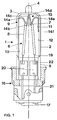
- Fig. 1 shows a halogen lamp 1 for general lighting purposes with a power of 75 W, which is suitable for direct connection to the 230 V network. It has a cylindrical piston 2 made of quartz glass with an outer diameter of approximately 12.5 mm with an inner diameter of 10.5 mm (with a tolerance of 0.8 mm) and a total length of approximately 60 mm (previously 86 mm). One end of the piston 2 is shaped into a dome 3 which has a pump tip 4 in the center. The other end of the piston is closed with a pinch seal 5 to which a bayonet base 16 is attached.
- the flask with a volume of 1.65 cm 3 is filled with an inert gas mixture of 80% Kr and 20% N 2 , to which a halogen addition of 0.005% CBrClF 2 is added.
- the maximum outside diameter of the lamp is 18 mm.
- the luminous element 6 is held by a frame 9, which consists of a support wire made of tungsten with a diameter 280 ⁇ m
- the frame 9 is essentially bent in a plane which contains the lamp axis in such a way that a transverse part lies between its two legs 10 and 11, which lie axially parallel to one another on the inner wall 12 of the bulb 13, which spans the inside diameter of the piston, and further frame parts are designated by reference numerals 14a to 14f.
- the two luminous coil sections 8 merge into short, about 4 mm long, uncoiled sections 19, which act as internal power supply lines.
- the inner power supply lines 19 are melted into the pinch seal 5 over a length of 3 mm and welded there to sealing foils 20 made of molybdenum.
- the wire diameter of the filament and the power supply is 36 ⁇ m.
- an area 22 of approximately 2 ⁇ 2 mm is dabbed on each foil with a welding aid (platinum paste).
- the power leads 19 protrude from the pinch seal only about 1 mm into the piston volume.
- contact pins 21 are welded, which protrude beyond the end of the pinch seal 5 and are connected to the contact lugs 17 on the bayonet base 16.
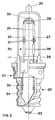
- FIG. 2 the structure of which essentially corresponds to the first exemplary embodiment, it is a 230 V lamp with a power between 25 and 60 W, the total length of which is 70 mm (instead of approximately 90 mm previously) is.
- the luminous element including the power supply lines is dimensioned differently.
- the wire diameter is approximately 15 to 45 ⁇ m depending on the power.
- the luminous element 25 is bent in a U-shape.
- the two legs of the luminous element, which run parallel to the lamp axis, are in turn subdivided into two double-coiled luminous sections 26, which are each connected to one another by single-coiled sections 27.
- the connecting part 28 of the U is simply coiled. It is arranged transversely to the lamp axis in the vicinity of the pump tip 24. Its ends are angled by 90 ° and each extend to a section 26.
- the luminous element is fixed by an oval glass web 30, which is formed from the material of the cob.
- the connecting part 28 is squeezed in the glass web 30.
- the luminous element 25 is fixed in the region of the simply coiled sections 27 by a further glass web 31, which has a circular cross section.
- a screw base 32 is fastened to the pinch seal 29 of the piston, the contact surfaces 33 of which are connected in a known manner, but without interposed fuses, to the outer contact pins 35 of the piston via lead wires 34.
- the effectiveness of the measure according to the invention is particularly impressively underlined by the fact that in the event of deliberate malfunction of a 75W / 12V lamp on the 220 V network, the arc was reliably extinguished and no bulb explosion occurred.
- the arrangement according to the invention results in higher reliability, shorter response times and simpler and more cost-effective production with halogen incandescent lamps squeezed on one side for medium-voltage and high-voltage operation.
- FIG. 3 shows a reflector lamp 40 with an operating voltage of 230 V and a power of 50 W.
- the built-in lamp 41 itself is constructed similarly to that in FIG. 2. It has an outer diameter of approx. 13 mm. For better compactification, it has only a single glass web 42, which sits in the area of the piston crown. In this way, it has an overall length of only 38 mm, calculated from the pinch to the pump tip. The lamp can therefore be accommodated in a very compact reflector 43 made of glass with an outer diameter of 50 mm.
- a perforated disk 44 made of sheet metal at the level of the pinch pin 45 serves for better fixation.
- the reflector tapers towards the reflector neck 46 to an outer diameter of 20 mm. Its total length is 49 mm. It also has an effect the shown spiral design with two short parallel legs 47, which are close to each other, advantageously on the light distribution in the reflector. The dimensions of the two spiral legs are approx. 0.5 x 9.5 mm.
- the reflector lamp has a glass base 48 formed directly on the reflector neck. This essentially consists of a flat end surface 49 at the end of the reflector neck.
- the outer power supply lines 50 of the built-in lamp are led out through two openings and crimped into two contact pin sleeves 51.
- the contact pin sleeves themselves are riveted into the openings.
- the principle of this glass base is similar to that described in DE-GM 82 34 509.
- this reflector incandescent lamp has a conventional screw base or bayonet base instead of the glass base.
- FIG. 3 has particular advantages over known reflector lamps, since both the number of components (now six components, previously ten components including the intermediate part) can be reduced and the assembly technology can be considerably simplified. The new product can therefore be manufactured much more cost-effectively and time-saving.
- the cover plate can also be dispensed with if the quartz glass is doped in a manner known per se in order to ensure the necessary UV protection.
- the invention is not restricted to the exemplary embodiments shown.
- it is also suitable for halogen incandescent lamps for mains operation at 110 V.
- the two filament sections can be subdivided again.
- the impact resistance of the filament can be increased Measures to be further improved.
- the filling can also consist of other components known per se, for example CH 2 Br 2 can be used as halogen additive.
- tubular fixtures made of quartz glass (glass webs), which are formed from the material of the bulb can be used for fixing the luminous element.
- the luminous element is arranged axially and the power supply, which leads to its end on the pinch side, is melted into the pinch as an uncoiled section.
- the invention provides an inexpensive halogen incandescent lamp with low power consumption down to 25 W for direct mains connection, as is of particular interest for general lighting.
- Preferred power levels are a maximum of 250 W.
- the invention is particularly advantageous for one-sided pinched halogen incandescent lamps with low power (25 to 75 W), since here the space-saving effect of the invention is most effective, particularly when using a glass or bayonet base.
Landscapes
- Vessels And Coating Films For Discharge Lamps (AREA)
- Non-Portable Lighting Devices Or Systems Thereof (AREA)
- Common Detailed Techniques For Electron Tubes Or Discharge Tubes (AREA)
- Fastening Of Light Sources Or Lamp Holders (AREA)
Applications Claiming Priority (4)
| Application Number | Priority Date | Filing Date | Title |
|---|---|---|---|
| DE29607132U | 1996-04-19 | ||
| DE29607132U DE29607132U1 (de) | 1996-04-19 | 1996-04-19 | Halogenlampe |
| DE29620098U DE29620098U1 (de) | 1996-11-20 | 1996-11-20 | Halogenlampe |
| DE29620098U | 1996-11-20 |
Publications (2)
| Publication Number | Publication Date |
|---|---|
| EP0802561A1 true EP0802561A1 (fr) | 1997-10-22 |
| EP0802561B1 EP0802561B1 (fr) | 2000-07-19 |
Family
ID=26058875
Family Applications (2)
| Application Number | Title | Priority Date | Filing Date |
|---|---|---|---|
| EP97105626A Expired - Lifetime EP0802561B1 (fr) | 1996-04-19 | 1997-04-04 | Lampe halogène |
| EP97922834A Expired - Lifetime EP0839381B1 (fr) | 1996-04-19 | 1997-04-14 | Lampe a reflecteur |
Family Applications After (1)
| Application Number | Title | Priority Date | Filing Date |
|---|---|---|---|
| EP97922834A Expired - Lifetime EP0839381B1 (fr) | 1996-04-19 | 1997-04-14 | Lampe a reflecteur |
Country Status (9)
| Country | Link |
|---|---|
| US (2) | US6060820A (fr) |
| EP (2) | EP0802561B1 (fr) |
| JP (2) | JP4054086B2 (fr) |
| KR (1) | KR100455460B1 (fr) |
| CN (1) | CN1083146C (fr) |
| DE (2) | DE59702042D1 (fr) |
| ES (1) | ES2160351T3 (fr) |
| HU (2) | HU220535B1 (fr) |
| WO (1) | WO1997040511A1 (fr) |
Cited By (6)
| Publication number | Priority date | Publication date | Assignee | Title |
|---|---|---|---|---|
| US6060820A (en) * | 1996-04-19 | 2000-05-09 | Patent-Treuhand-Gesellschaft Fuer Elektrische Gluehlampen Mbh | Reflector lamp |
| WO2000070652A1 (fr) * | 1999-05-18 | 2000-11-23 | Koninklijke Philips Electronics N.V. | Lampe electrique a incandescence |
| WO2008145570A2 (fr) * | 2007-05-25 | 2008-12-04 | Osram Gesellschaft mit beschränkter Haftung | Ensemble constitué d'une lampe et d'une douille de lampe |
| WO2010000325A1 (fr) * | 2008-07-04 | 2010-01-07 | Osram Gesellschaft mit beschränkter Haftung | Dispositif d'alimentation en courant pour une électrode d'une lampe électrique équipée d'un tel dispositif d'alimentation en courant |
| EP2544213A1 (fr) * | 2010-03-03 | 2013-01-09 | Panasonic Corporation | Lampe |
| DE102012219135A1 (de) | 2012-10-19 | 2014-04-24 | Osram Gmbh | Reflektorlampe |
Families Citing this family (15)
| Publication number | Priority date | Publication date | Assignee | Title |
|---|---|---|---|---|
| WO1999012187A1 (fr) * | 1997-09-03 | 1999-03-11 | Koninklijke Philips Electronics N.V. | Lampe a incandescence |
| US6611102B2 (en) * | 2000-03-10 | 2003-08-26 | Matsushita Electric Industrial Co., Ltd. | Tungsten-halogen light bulb, and reflector lamp using the same |
| US8114163B2 (en) * | 2000-04-10 | 2012-02-14 | Biomet Manufacturing Corp. | Method and apparatus for adjusting height and angle for a radial head |
| US6536918B1 (en) * | 2000-08-23 | 2003-03-25 | General Electric Company | Lighting system for generating pre-determined beam-pattern |
| US6653782B2 (en) * | 2001-12-27 | 2003-11-25 | Koninklijke Philips Electronics N.V. | Fuse and safety switch for halogen incandescent lamps |
| US7227308B2 (en) * | 2003-11-24 | 2007-06-05 | General Electric Company | Assembly for precision focus of compact PAR lamps |
| DE102004044364A1 (de) * | 2004-09-10 | 2006-03-16 | Patent-Treuhand-Gesellschaft für elektrische Glühlampen mbH | Glühlampe |
| JP4492337B2 (ja) * | 2004-12-14 | 2010-06-30 | ウシオ電機株式会社 | 光源ユニット |
| DE102006014643A1 (de) * | 2006-03-29 | 2007-10-04 | Patent-Treuhand-Gesellschaft für elektrische Glühlampen mbH | Lampe mit Halteelement |
| DE102006020224A1 (de) * | 2006-05-02 | 2007-11-08 | Patent-Treuhand-Gesellschaft für elektrische Glühlampen mbH | Reflektorvorrichtung für eine Beleuchtungsvorrichtung |
| DE102006049908A1 (de) * | 2006-10-23 | 2008-04-30 | Patent-Treuhand-Gesellschaft für elektrische Glühlampen mbH | Elektrische Lichtquelle, insbesondere für den Einsatz in einem Reflektor |
| DE202007009060U1 (de) * | 2007-06-28 | 2008-08-07 | Osram Gesellschaft mit beschränkter Haftung | Elektrische Verbindung zwischen wenigstens zwei Teilen und elektrisches Gerät mit einer derartigen Verbindung |
| US20110115372A1 (en) * | 2009-11-17 | 2011-05-19 | General Electric Company | Electric lamp with pin connectors and method of manufacture |
| US8193689B2 (en) * | 2010-10-11 | 2012-06-05 | General Electric Company | Metal halide lamp shrouding |
| FR3086808B1 (fr) * | 2018-10-02 | 2021-10-08 | Commissariat Energie Atomique | Connecteur |
Citations (2)
| Publication number | Priority date | Publication date | Assignee | Title |
|---|---|---|---|---|
| DE9102566U1 (de) * | 1990-03-15 | 1991-05-23 | Patent-Treuhand-Gesellschaft für elektrische Glühlampen mbH, 8000 München | Halogenglühlampe |
| DE29607132U1 (de) * | 1996-04-19 | 1996-07-04 | Patent-Treuhand-Gesellschaft für elektrische Glühlampen mbH, 81543 München | Halogenlampe |
Family Cites Families (25)
| Publication number | Priority date | Publication date | Assignee | Title |
|---|---|---|---|---|
| NL7507227A (nl) * | 1975-06-18 | 1976-12-21 | Philips Nv | Gloeilamp-reflektoreenheid. |
| US4079283A (en) * | 1977-04-11 | 1978-03-14 | Gte Sylvania Incorporated | High wattage incandescent lamp with support for a planar segmented filament |
| US4132922A (en) * | 1977-10-13 | 1979-01-02 | Westinghouse Electric Corp. | Gas-filled incandescent lamp with integral fuse assembly |
| NL179957C (nl) * | 1980-03-21 | 1986-12-01 | Philips Nv | Halogeengloeilamp. |
| US4354137A (en) * | 1980-07-15 | 1982-10-12 | Westinghouse Electric Corp. | Incandescent lamp having seal-anchored filament mount, and method of making such lamp |
| DE8234509U1 (de) * | 1982-12-08 | 1984-05-17 | Patent-Treuhand-Gesellschaft für elektrische Glühlampen mbH, 8000 München | Kompakte Niederdruckentladungslampe mit Sockel und Fassung |
| NL8401209A (nl) * | 1984-04-16 | 1985-11-18 | Philips Nv | Elektrische gloeilamp. |
| JPH0334837Y2 (fr) * | 1985-04-30 | 1991-07-24 | ||
| US4855634A (en) * | 1985-12-19 | 1989-08-08 | Gte Products Corporation | Reflector and eyelet construction for reflector-type lamps |
| JPS62264548A (ja) * | 1986-10-03 | 1987-11-17 | 株式会社東芝 | シ−ルドビ−ム形電球用レンズ |
| US4797794A (en) * | 1987-08-12 | 1989-01-10 | Gte Products Corporation | Reflector lamp |
| DE8803881U1 (de) * | 1988-03-22 | 1988-05-11 | Patent-Treuhand-Gesellschaft für elektrische Glühlampen mbH, 8000 München | Kompakte Reflektorlampe |
| US4914342A (en) * | 1988-06-30 | 1990-04-03 | North American Philips Corp. | Narrow spot reflector lamp with diffusing reflector |
| US5032758A (en) * | 1989-09-28 | 1991-07-16 | General Electric Company | Precision tubulation for self mounting lamp |
| DE4008367A1 (de) * | 1990-03-15 | 1991-09-26 | Patent Treuhand Ges Fuer Elektrische Gluehlampen Mbh | Einseitig gequetschte halogengluehlampe |
| US5146134A (en) * | 1990-03-15 | 1992-09-08 | Patent Treuhand Gesellschaft Fur Elektrische Gluhlampen M.B.H. | Halogen incandescent lamp, particularly for operation from power networks, and method of its manufacture |
| JPH03280349A (ja) * | 1990-03-28 | 1991-12-11 | Iwasaki Electric Co Ltd | 反射形放電灯 |
| JPH04138656A (ja) * | 1990-09-29 | 1992-05-13 | Toshiba Lighting & Technol Corp | 反射鏡付き電球 |
| GB9103623D0 (en) * | 1991-02-21 | 1991-04-10 | Thorn Lamps Ltd Ge | Improvements in lamps and lamp holders for display lighting |
| US5412542A (en) * | 1991-03-20 | 1995-05-02 | Man-D-Tec, Inc. | Down lighting systems and fixtures therefor |
| EP0633603B1 (fr) * | 1993-07-05 | 1997-03-12 | Koninklijke Philips Electronics N.V. | Ensemble lampe/réflecteur |
| JPH07211299A (ja) * | 1994-01-20 | 1995-08-11 | Minoru Nishibori | リフレクタ付きハロゲン電球 |
| JPH087846A (ja) * | 1994-06-21 | 1996-01-12 | Ushio Inc | ハロゲン電球 |
| DE19548521A1 (de) * | 1995-12-22 | 1997-06-26 | Patent Treuhand Ges Fuer Elektrische Gluehlampen Mbh | Lampen-Reflektor-Einheit |
| EP0802561B1 (fr) * | 1996-04-19 | 2000-07-19 | Patent-Treuhand-Gesellschaft für elektrische Glühlampen mbH | Lampe halogène |
-
1997
- 1997-04-04 EP EP97105626A patent/EP0802561B1/fr not_active Expired - Lifetime
- 1997-04-04 DE DE59702042T patent/DE59702042D1/de not_active Expired - Lifetime
- 1997-04-12 US US08/973,702 patent/US6060820A/en not_active Expired - Lifetime
- 1997-04-14 CN CN97190332A patent/CN1083146C/zh not_active Expired - Fee Related
- 1997-04-14 WO PCT/DE1997/000750 patent/WO1997040511A1/fr active IP Right Grant
- 1997-04-14 ES ES97922834T patent/ES2160351T3/es not_active Expired - Lifetime
- 1997-04-14 HU HU9901460A patent/HU220535B1/hu not_active IP Right Cessation
- 1997-04-14 DE DE59703946T patent/DE59703946D1/de not_active Expired - Lifetime
- 1997-04-14 JP JP11190897A patent/JP4054086B2/ja not_active Expired - Fee Related
- 1997-04-14 EP EP97922834A patent/EP0839381B1/fr not_active Expired - Lifetime
- 1997-04-14 KR KR1019970709516A patent/KR100455460B1/ko not_active IP Right Cessation
- 1997-04-14 JP JP9537577A patent/JPH11508402A/ja active Pending
- 1997-04-18 US US08/843,523 patent/US5883469A/en not_active Expired - Lifetime
- 1997-04-18 HU HU9700773A patent/HU218813B/hu not_active IP Right Cessation
Patent Citations (2)
| Publication number | Priority date | Publication date | Assignee | Title |
|---|---|---|---|---|
| DE9102566U1 (de) * | 1990-03-15 | 1991-05-23 | Patent-Treuhand-Gesellschaft für elektrische Glühlampen mbH, 8000 München | Halogenglühlampe |
| DE29607132U1 (de) * | 1996-04-19 | 1996-07-04 | Patent-Treuhand-Gesellschaft für elektrische Glühlampen mbH, 81543 München | Halogenlampe |
Cited By (10)
| Publication number | Priority date | Publication date | Assignee | Title |
|---|---|---|---|---|
| US6060820A (en) * | 1996-04-19 | 2000-05-09 | Patent-Treuhand-Gesellschaft Fuer Elektrische Gluehlampen Mbh | Reflector lamp |
| WO2000070652A1 (fr) * | 1999-05-18 | 2000-11-23 | Koninklijke Philips Electronics N.V. | Lampe electrique a incandescence |
| WO2008145570A2 (fr) * | 2007-05-25 | 2008-12-04 | Osram Gesellschaft mit beschränkter Haftung | Ensemble constitué d'une lampe et d'une douille de lampe |
| WO2008145570A3 (fr) * | 2007-05-25 | 2009-04-16 | Osram Gmbh | Ensemble constitué d'une lampe et d'une douille de lampe |
| WO2010000325A1 (fr) * | 2008-07-04 | 2010-01-07 | Osram Gesellschaft mit beschränkter Haftung | Dispositif d'alimentation en courant pour une électrode d'une lampe électrique équipée d'un tel dispositif d'alimentation en courant |
| EP2544213A1 (fr) * | 2010-03-03 | 2013-01-09 | Panasonic Corporation | Lampe |
| EP2544213A4 (fr) * | 2010-03-03 | 2013-09-11 | Panasonic Corp | Lampe |
| DE102012219135A1 (de) | 2012-10-19 | 2014-04-24 | Osram Gmbh | Reflektorlampe |
| US10004134B2 (en) | 2012-10-19 | 2018-06-19 | Ledvance Gmbh | Reflector lamp |
| US10594067B2 (en) | 2012-10-19 | 2020-03-17 | Ledvance Gmbh | Reflector lamp |
Also Published As
| Publication number | Publication date |
|---|---|
| KR19990028205A (ko) | 1999-04-15 |
| HUP9901460A3 (en) | 2001-05-28 |
| KR100455460B1 (ko) | 2004-12-17 |
| JPH1040879A (ja) | 1998-02-13 |
| US5883469A (en) | 1999-03-16 |
| HUP9700773A3 (en) | 2000-02-28 |
| EP0802561B1 (fr) | 2000-07-19 |
| ES2160351T3 (es) | 2001-11-01 |
| HU218813B (hu) | 2000-12-28 |
| EP0839381A1 (fr) | 1998-05-06 |
| JP4054086B2 (ja) | 2008-02-27 |
| HU9700773D0 (en) | 1997-06-30 |
| CN1083146C (zh) | 2002-04-17 |
| DE59703946D1 (de) | 2001-08-09 |
| JPH11508402A (ja) | 1999-07-21 |
| WO1997040511A1 (fr) | 1997-10-30 |
| EP0839381B1 (fr) | 2001-07-04 |
| HU220535B1 (hu) | 2002-03-28 |
| HUP9901460A2 (hu) | 1999-08-30 |
| US6060820A (en) | 2000-05-09 |
| HUP9700773A2 (en) | 1997-12-29 |
| DE59702042D1 (de) | 2000-08-24 |
| CN1188562A (zh) | 1998-07-22 |
Similar Documents
| Publication | Publication Date | Title |
|---|---|---|
| EP0802561B1 (fr) | Lampe halogène | |
| DE3005017C2 (fr) | ||
| DE2718642C2 (de) | Elektrode für eine Hochdruck-Metallhalogenidlampe | |
| DE69405181T2 (de) | Hochdruck-Entladungslampe | |
| DE69806085T2 (de) | Ringförmige Fluoreszenzlampe | |
| DE2332274A1 (de) | Hochdruckgasentladungslampe | |
| DE69404926T2 (de) | Hochdruck-Entladungslampe | |
| EP1527477B1 (fr) | Lampe electrique a incandescence | |
| DE69311947T2 (de) | Doppelend Bogenentladungslampe | |
| DE3885822T2 (de) | Metalldampfentladungslampe. | |
| EP0269957B1 (fr) | Lampe à décharge à haute pression munie d'un pincement unique | |
| DE69911735T2 (de) | Hochdruckentladungslampe | |
| DE29620098U1 (de) | Halogenlampe | |
| DE69915253T2 (de) | Hochdruckentladungslampe | |
| WO2001024222A1 (fr) | Lampe a decharge haute pression | |
| DE29607132U1 (de) | Halogenlampe | |
| DE2753898A1 (de) | Hochintensive entladungslampe | |
| DE69020465T3 (de) | Einseitig gequetschte elektrische Metalldampfentladungslampe. | |
| DE3132699C2 (de) | Natriumdampf-Hochdrucklampe | |
| EP0154383B1 (fr) | Electrode chauffable pour lampes à gaz à décharge à haute pression | |
| DE2645794C3 (de) | Leuchtstofflampe in Rechteckform und Verfahren zu ihrer Herstellung | |
| DE60026516T2 (de) | Leuchtstofflampe | |
| DE3124261A1 (de) | "elektrische gluehlampe" | |
| DE9102566U1 (de) | Halogenglühlampe | |
| AT398864B (de) | Halogenglühlampe |
Legal Events
| Date | Code | Title | Description |
|---|---|---|---|
| PUAI | Public reference made under article 153(3) epc to a published international application that has entered the european phase |
Free format text: ORIGINAL CODE: 0009012 |
|
| AK | Designated contracting states |
Kind code of ref document: A1 Designated state(s): BE DE FR GB IT NL |
|
| 17P | Request for examination filed |
Effective date: 19971105 |
|
| GRAG | Despatch of communication of intention to grant |
Free format text: ORIGINAL CODE: EPIDOS AGRA |
|
| 17Q | First examination report despatched |
Effective date: 19990901 |
|
| GRAG | Despatch of communication of intention to grant |
Free format text: ORIGINAL CODE: EPIDOS AGRA |
|
| GRAH | Despatch of communication of intention to grant a patent |
Free format text: ORIGINAL CODE: EPIDOS IGRA |
|
| GRAH | Despatch of communication of intention to grant a patent |
Free format text: ORIGINAL CODE: EPIDOS IGRA |
|
| GRAA | (expected) grant |
Free format text: ORIGINAL CODE: 0009210 |
|
| AK | Designated contracting states |
Kind code of ref document: B1 Designated state(s): BE DE FR GB IT NL |
|
| REF | Corresponds to: |
Ref document number: 59702042 Country of ref document: DE Date of ref document: 20000824 |
|
| ITF | It: translation for a ep patent filed | ||
| GBT | Gb: translation of ep patent filed (gb section 77(6)(a)/1977) |
Effective date: 20000920 |
|
| ET | Fr: translation filed | ||
| PLBE | No opposition filed within time limit |
Free format text: ORIGINAL CODE: 0009261 |
|
| STAA | Information on the status of an ep patent application or granted ep patent |
Free format text: STATUS: NO OPPOSITION FILED WITHIN TIME LIMIT |
|
| 26N | No opposition filed | ||
| REG | Reference to a national code |
Ref country code: GB Ref legal event code: IF02 |
|
| PGFP | Annual fee paid to national office [announced via postgrant information from national office to epo] |
Ref country code: NL Payment date: 20030410 Year of fee payment: 7 Ref country code: GB Payment date: 20030410 Year of fee payment: 7 |
|
| PGFP | Annual fee paid to national office [announced via postgrant information from national office to epo] |
Ref country code: BE Payment date: 20030428 Year of fee payment: 7 |
|
| PGFP | Annual fee paid to national office [announced via postgrant information from national office to epo] |
Ref country code: FR Payment date: 20030429 Year of fee payment: 7 |
|
| PG25 | Lapsed in a contracting state [announced via postgrant information from national office to epo] |
Ref country code: GB Free format text: LAPSE BECAUSE OF NON-PAYMENT OF DUE FEES Effective date: 20040404 |
|
| PG25 | Lapsed in a contracting state [announced via postgrant information from national office to epo] |
Ref country code: BE Free format text: LAPSE BECAUSE OF NON-PAYMENT OF DUE FEES Effective date: 20040430 |
|
| BERE | Be: lapsed |
Owner name: *PATENT-TREUHAND-G.- FUR ELEKTRISCHE GLUHLAMPEN M. Effective date: 20040430 |
|
| PG25 | Lapsed in a contracting state [announced via postgrant information from national office to epo] |
Ref country code: NL Free format text: LAPSE BECAUSE OF NON-PAYMENT OF DUE FEES Effective date: 20041101 |
|
| GBPC | Gb: european patent ceased through non-payment of renewal fee | ||
| PG25 | Lapsed in a contracting state [announced via postgrant information from national office to epo] |
Ref country code: FR Free format text: LAPSE BECAUSE OF NON-PAYMENT OF DUE FEES Effective date: 20041231 |
|
| NLV4 | Nl: lapsed or anulled due to non-payment of the annual fee |
Effective date: 20041101 |
|
| REG | Reference to a national code |
Ref country code: FR Ref legal event code: ST |
|
| PG25 | Lapsed in a contracting state [announced via postgrant information from national office to epo] |
Ref country code: IT Free format text: LAPSE BECAUSE OF NON-PAYMENT OF DUE FEES;WARNING: LAPSES OF ITALIAN PATENTS WITH EFFECTIVE DATE BEFORE 2007 MAY HAVE OCCURRED AT ANY TIME BEFORE 2007. THE CORRECT EFFECTIVE DATE MAY BE DIFFERENT FROM THE ONE RECORDED. Effective date: 20050404 |
|
| REG | Reference to a national code |
Ref country code: DE Ref legal event code: R081 Ref document number: 59702042 Country of ref document: DE Owner name: LEDVANCE GMBH, DE Free format text: FORMER OWNER: OSRAM GESELLSCHAFT MIT BESCHRAENKTER HAFTUNG, 81543 MUENCHEN, DE Effective date: 20111130 Ref country code: DE Ref legal event code: R081 Ref document number: 59702042 Country of ref document: DE Owner name: OSRAM GMBH, DE Free format text: FORMER OWNER: OSRAM GESELLSCHAFT MIT BESCHRAENKTER HAFTUNG, 81543 MUENCHEN, DE Effective date: 20111130 |
|
| REG | Reference to a national code |
Ref country code: DE Ref legal event code: R081 Ref document number: 59702042 Country of ref document: DE Owner name: LEDVANCE GMBH, DE Free format text: FORMER OWNER: OSRAM AG, 81543 MUENCHEN, DE Effective date: 20130205 Ref country code: DE Ref legal event code: R081 Ref document number: 59702042 Country of ref document: DE Owner name: OSRAM GMBH, DE Free format text: FORMER OWNER: OSRAM AG, 81543 MUENCHEN, DE Effective date: 20130205 |
|
| REG | Reference to a national code |
Ref country code: DE Ref legal event code: R081 Ref document number: 59702042 Country of ref document: DE Owner name: LEDVANCE GMBH, DE Free format text: FORMER OWNER: OSRAM GMBH, 81543 MUENCHEN, DE Effective date: 20130822 Ref country code: DE Ref legal event code: R081 Ref document number: 59702042 Country of ref document: DE Owner name: OSRAM GMBH, DE Free format text: FORMER OWNER: OSRAM GMBH, 81543 MUENCHEN, DE Effective date: 20130822 |
|
| PGFP | Annual fee paid to national office [announced via postgrant information from national office to epo] |
Ref country code: DE Payment date: 20160421 Year of fee payment: 20 |
|
| REG | Reference to a national code |
Ref country code: DE Ref legal event code: R081 Ref document number: 59702042 Country of ref document: DE Owner name: LEDVANCE GMBH, DE Free format text: FORMER OWNER: OSRAM GMBH, 80807 MUENCHEN, DE |
|
| REG | Reference to a national code |
Ref country code: DE Ref legal event code: R071 Ref document number: 59702042 Country of ref document: DE |