EP0802440A2 - Am Kopf montierter Bildanzeigeapparat - Google Patents
Am Kopf montierter Bildanzeigeapparat Download PDFInfo
- Publication number
- EP0802440A2 EP0802440A2 EP96112994A EP96112994A EP0802440A2 EP 0802440 A2 EP0802440 A2 EP 0802440A2 EP 96112994 A EP96112994 A EP 96112994A EP 96112994 A EP96112994 A EP 96112994A EP 0802440 A2 EP0802440 A2 EP 0802440A2
- Authority
- EP
- European Patent Office
- Prior art keywords
- axis
- principal ray
- center
- reflecting surface
- image
- Prior art date
- Legal status (The legal status is an assumption and is not a legal conclusion. Google has not performed a legal analysis and makes no representation as to the accuracy of the status listed.)
- Granted
Links
- 230000003287 optical effect Effects 0.000 claims abstract description 328
- 210000005252 bulbus oculi Anatomy 0.000 claims abstract description 142
- 230000009471 action Effects 0.000 claims abstract description 13
- 210000001747 pupil Anatomy 0.000 claims description 86
- 101100083446 Danio rerio plekhh1 gene Proteins 0.000 claims description 32
- 101100129500 Caenorhabditis elegans max-2 gene Proteins 0.000 claims description 12
- 230000004075 alteration Effects 0.000 description 51
- 201000009310 astigmatism Diseases 0.000 description 31
- 238000012937 correction Methods 0.000 description 18
- 230000002349 favourable effect Effects 0.000 description 16
- 210000001508 eye Anatomy 0.000 description 12
- 238000010586 diagram Methods 0.000 description 10
- 206010010071 Coma Diseases 0.000 description 9
- 230000000007 visual effect Effects 0.000 description 6
- 239000000470 constituent Substances 0.000 description 5
- 230000000694 effects Effects 0.000 description 5
- 239000011521 glass Substances 0.000 description 5
- 230000014509 gene expression Effects 0.000 description 3
- 210000003128 head Anatomy 0.000 description 3
- 230000002093 peripheral effect Effects 0.000 description 3
- 230000002123 temporal effect Effects 0.000 description 3
- 241000226585 Antennaria plantaginifolia Species 0.000 description 2
- 230000008859 change Effects 0.000 description 2
- 238000010276 construction Methods 0.000 description 2
- 238000007796 conventional method Methods 0.000 description 2
- 230000000717 retained effect Effects 0.000 description 2
- 230000015572 biosynthetic process Effects 0.000 description 1
- 230000008602 contraction Effects 0.000 description 1
- 210000005069 ears Anatomy 0.000 description 1
- 239000013013 elastic material Substances 0.000 description 1
- 239000004973 liquid crystal related substance Substances 0.000 description 1
- 238000000034 method Methods 0.000 description 1
- 238000012545 processing Methods 0.000 description 1
- 210000001525 retina Anatomy 0.000 description 1
- 230000002441 reversible effect Effects 0.000 description 1
- 238000000926 separation method Methods 0.000 description 1
- 230000003595 spectral effect Effects 0.000 description 1
- 238000012546 transfer Methods 0.000 description 1
Images


Classifications
-
- G—PHYSICS
- G02—OPTICS
- G02B—OPTICAL ELEMENTS, SYSTEMS OR APPARATUS
- G02B27/00—Optical systems or apparatus not provided for by any of the groups G02B1/00 - G02B26/00, G02B30/00
- G02B27/01—Head-up displays
- G02B27/017—Head mounted
- G02B27/0172—Head mounted characterised by optical features
-
- G—PHYSICS
- G02—OPTICS
- G02B—OPTICAL ELEMENTS, SYSTEMS OR APPARATUS
- G02B27/00—Optical systems or apparatus not provided for by any of the groups G02B1/00 - G02B26/00, G02B30/00
- G02B27/01—Head-up displays
- G02B27/0101—Head-up displays characterised by optical features
- G02B2027/011—Head-up displays characterised by optical features comprising device for correcting geometrical aberrations, distortion
-
- G—PHYSICS
- G02—OPTICS
- G02B—OPTICAL ELEMENTS, SYSTEMS OR APPARATUS
- G02B27/00—Optical systems or apparatus not provided for by any of the groups G02B1/00 - G02B26/00, G02B30/00
- G02B27/01—Head-up displays
- G02B27/017—Head mounted
- G02B2027/0178—Eyeglass type
Definitions
- the present invention relates to an image display apparatus and, more particularly, to a head- or face-mounted image display apparatus that can be retained on the observer's head or face.
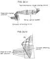
- Fig. 24(a) shows the entire optical system of the conventional image display apparatus
- Fig. 24(b) shows a part of an ocular optical system used in the image display apparatus.
- an image that is displayed by an image display device is transmitted as an aerial image by a relay optical system including a positive lens, and the aerial image is projected into an observer's eyeball as an enlarged image by an ocular optical system formed from a concave reflecting mirror.
- U.S. Patent No. 4,669,810 discloses another type of convention image display apparatus.
- this apparatus as shown in Fig. 25, an image of a CRT is transmitted through a relay optical system to form an intermediate image, and the image is projected into an observer's eye by a combination of a reflection holographic element and a combiner having a hologram surface.
- Japanese Patent Application Unexamined Publication (KOKAI) No. 62-214782 (1987) discloses another type of conventional image display apparatus. As shown in Figs. 26(a) and 26(b), the conventional image display apparatus is designed to enable an image of an image display device to be directly observed as an enlarged image through an ocular lens.
- U.S. Patent No. 4,026,641 discloses another type of conventional image display apparatus.
- an image of an image display device is transferred to a curved object surface by an image transfer device, and the image transferred to the object surface is projected in the air by a toric reflector.
- U.S. Reissued Patent No. 27,356 discloses another type of conventional image display apparatus. As shown in Fig. 28, the apparatus is an ocular optical system designed to project an object surface onto an exit pupil by a semitransparent concave mirror and a semitransparent plane mirror.
- a reflecting surface and a transmitting surface which constitute an optical system, are formed by using a spherical surface, a rotationally symmetric aspherical surface, a toric surface, an anamorphic surface, etc. Therefore, it has heretofore been impossible to favorably correct ray aberration and distortion at the same time.
- an image for observation is not favorably corrected for both aberration and distortion, the image is distorted as it is viewed by an observer. If the observation image is distorted such that images viewed with the user's left and right eyes are not in symmetry with each other, the two images cannot properly be fused into a single image. In the case of displaying a figure or the like, the displayed figure appears to be distorted, making it impossible to correctly recognize the shape of the displayed figure.
- an object of the present invention is to provide a head-mounted image display apparatus capable of providing an observation image which is clear and has minimal distortion even at a wide field angle.
- the present invention provides a head-mounted image display apparatus which has an image display device, and an ocular optical system for leading an image formed by the image display device to an observer's eyeball position without forming an intermediate image so that the image can be observed as a virtual image.
- the ocular optical system has at least one reflecting surface having reflecting action.
- the at least one reflecting surface has a surface configuration defined by a plane-symmetry three-dimensional surface which has no axis of rotational symmetry in nor out of the surface, and which has only one plane of symmetry.
- the reflecting surface it is desirable for the reflecting surface to satisfy either or both of the following conditions (1) and (2): (1)
- the plane of symmetry of the plane-symmetry three-dimensional surface should lie in either the YZ-plane or a plane parallel to the YZ-plane.
- either or both of the reflective refracting power of the axial principal ray reflecting region of the reflecting surface in the YZ-plane and the reflective refracting power in a plane perpendicular to the YZ-plane should be positive.
- the present invention provides a head-mounted image display apparatus which has an image display device, and an ocular optical system for leading an image formed by the image display device to an observer's eyeball position without forming an intermediate image so that the image can be observed as a virtual image.
- the ocular optical system has at least one reflecting surface of a non-rotationally symmetric surface configuration having no axis of rotational symmetry in nor out of the surface.
- the reflecting surface of the non-rotationally symmetric surface configuration satisfies the following condition: -0.2 ⁇ DY max4 ⁇ 0.2 where DY max4 denotes all the values of DY2-DY1, DY2-DY3, DY2-DY4, DY2-DY5, and DY2-DY6 when an effective area is defined for the reflecting surface as being an area formed by intersection of the reflecting surface and six principal rays, which are,
- the present invention provides a head-mounted image display apparatus which has an image display device, and an ocular optical system for leading an image formed by the image display device to an observer's eyeball position without forming an intermediate image so that the image can be observed as a virtual image.
- a final reflecting surface of the ocular optical system as viewed in the sequence of backward ray tracing in which light rays are traced from the pupil of the observer's eyeball to the image display device has a non-rotationally symmetric surface configuration having no axis of rotational symmetry in nor out of the surface.
- the reflecting surface of the non-rotationally symmetric surface configuration satisfies the following condition: 0.55 ⁇ D 2 XY11 ⁇ 4.0 where D 2 XY11 denotes the value of D 2 X2/D 2 Y2 when an effective area is defined for the reflecting surface as being an area formed by intersection of the reflecting surface and six principal rays, which are, with the Y-axis direction defined as a vertical direction
- the present invention provides a head-mounted image display apparatus which has an image display device, and an ocular optical system for leading an image formed by the image display device to an observer's eyeball position without forming an intermediate image so that the image can be observed as a virtual image.
- a reflecting surface of the ocular optical system other than a final reflecting surface of the ocular optical system as viewed in the sequence of backward ray tracing in which light rays are traced from the pupil of the observer's eyeball to the image display device has a non-rotationally symmetric surface configuration having no axis of rotational symmetry in nor out of the surface.
- the reflecting surface of the non-rotationally symmetric surface configuration satisfies the following condition: 0.55 ⁇ D 2 XY12 ⁇ 5 where D 2 XY12 denotes the value of D 2 X2/D 2 Y2 when an effective area is defined for the reflecting surface as being an area formed by intersection of the reflecting surface and six principal rays, which are, with the Y-axis direction defined as a vertical direction
- the present invention provides a head-mounted image display apparatus which has an image display device, and an ocular optical system for leading an image formed by the image display device to an observer's eyeball position without forming an intermediate image so that the image can be observed as a virtual image.
- the ocular optical system includes at least one reflecting surface of a non-rotationally symmetric surface configuration having no axis of rotational symmetry in nor out of the surface.
- a reflecting surface having the strongest reflective refracting power among those which constitute the ocular optical system satisfies the following condition: -0.015 ⁇ CX n2 M ⁇ 0.1 (1/mm) where CX n2 M denotes CXn-CX2 (n is 1, 3 to 6) when an effective area is defined for the reflecting surface as being an area formed by intersection of the reflecting surface and six principal rays,
- the present invention provides a head-mounted image display apparatus which has an image display device, and an ocular optical system for leading an image formed by the image display device to an observer's eyeball position without forming an intermediate image so that the image can be observed as a virtual image.
- the ocular optical system includes at least one reflecting surface of a non-rotationally symmetric surface configuration having no axis of rotational symmetry in nor out of the surface.
- a reflecting surface having the strongest reflective refracting power among those which constitute the ocular optical system satisfies the following condition: -0.015 ⁇ CY n2 M ⁇ 0.1 (1/mm) where CY n2 M denotes CYn-CY2 (n is 1, 3 to 6) when an effective area is defined for the reflecting surface as being an area formed by intersection of the reflecting surface and six principal rays, which are
- the present invention provides a head-mounted image display apparatus which has an image display device, and an ocular optical system for leading an image formed by the image display device to an observer's eyeball position without forming an intermediate image so that the image can be observed as a virtual image.
- the ocular optical system includes at least one reflecting surface having reflecting action.
- the at least one reflecting surface has a surface configuration defined by a plane-symmetry three-dimensional surface which has no axis of rotational symmetry in nor out of the surface, and which has only one plane of symmetry.
- a reflecting surface having the strongest reflective refracting power among those which constitute the ocular optical system satisfies the following condition: CXYM ⁇ 40 where CXYM denotes
- the present invention provides a head-mounted image display apparatus which has an image display device, and an ocular optical system for leading an image formed by the image display device to an observer's eyeball position without forming an intermediate image so that the image can be observed as a virtual image.
- the ocular optical system includes at least one reflecting surface having reflecting action.
- the at least one reflecting surface has a surface configuration defined by a plane-symmetry three-dimensional surface which has no axis of rotational symmetry in nor out of the surface, and which has only one plane of symmetry.
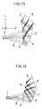
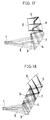
- Figs. 15 to 22 For the convenience of explanation, first, typical ocular optical systems which may be used in a head-mounted image display apparatus according to the present invention will be illustrated with Figs. 15 to 22.
- an ocular optical system 7 comprises a first surface 3, a second surface 4, and a third surface 5.
- a bundle of light rays emitted from an image display device 6 enters the ocular optical system 7 while being refracted by the third surface 5.
- the ray bundle is internally reflected by the first surface 3 and reflected by the second surface 4.
- the ray bundle is incident on the first surface 3 again and refracted by it so as to be projected into an observer's eyeball with the observer's iris position or eyeball rolling center as an exit pupil 1.
- an ocular optical system 7 comprises a first surface 3, a second surface 4, a third surface 5, and a fourth surface 9.
- a bundle of light rays emitted from an image display device 6 enters the ocular optical system 7 while being refracted by the third surface 5. Then, the ray bundle is internally reflected by the fourth surface 9 and further internally reflected by the second surface 4. Then, the ray bundle is incident on and refracted by the first surface 3 so as to be projected into an observer's eyeball with the observer's iris position or eyeball rolling center as an exit pupil 1.
- an ocular optical system 7 comprises a first surface 3, a second surface 4, a third surface 5, and a fourth surface 9.
- a bundle of light rays emitted from an image display device 6 enters the ocular optical system 7 while being refracted by the third surface 5.
- the ray bundle is internally reflected by the fourth surface 9 and internally reflected by the third surface 5.
- the ray bundle is internally reflected by the second surface 4 and refracted by the first surface 3 so as to be projected into an observer's eyeball with the observer's iris position or eyeball rolling center as an exit pupil 1.
- an ocular optical system 7 comprises a first surface 3, a second surface 4, a third surface 5, and a fourth surface 9.
- a bundle of light rays emitted from an image display device 6 enters the ocular optical system 7 while being refracted by the third surface 5.
- the ray bundle is internally reflected by the second surface 4 and further internally reflected by the fourth surface 9.
- the ray bundle is incident on the second surface 4 again and internally reflected by it.
- the ray bundle is incident on and refracted by the first surface 3 so as to be projected into an observer's eyeball with the observer's iris position or eyeball rolling center as an exit pupil 1.
- an ocular optical system 7 comprises a first surface 3, a second surface 4, a third surface 5, and a fourth surface 9.
- a bundle of light rays emitted from an image display device 6 enters the ocular optical system 7 while being refracted by the second surface 4. Then, the ray bundle is internally reflected by the third surface 5 and further internally reflected by the second surface 4. Then, the ray bundle is internally reflected by the fourth surface 9 and incident on the second surface 4 again and internally reflected by it. Then, the ray bundle is incident on and refracted by the first surface 3 so as to be projected into an observer's eyeball with the observer's iris position or eyeball rolling center as an exit pupil 1.
- a bundle of light rays emitted from an image display device 6 enters the ocular optical system 7 while being refracted by the third surface 5. Then, the ray bundle is internally reflected by the first surface 3 and further internally reflected by the third surface 5. Then, the ray bundle is internally reflected by the first surface 3 and further reflected by the second surface 4 to be incident on the first surface 3 once again. Then, the ray bundle is refracted by the first surface 3 so as to be projected into an observer's eyeball with the observer's iris position or eyeball rolling center as an exit pupil 1.
- a bundle of light rays emitted from an image display device 6 enters the ocular optical system 7 while being refracted by the first surface 3. Then, the ray bundle is internally reflected by the third surface 5 and further internally reflected by the first surface 3. Then, the ray bundle is internally reflected by the third surface 5 again and internally reflected by the first surface 3 once again. Then, the ray bundle is reflected by the second surface 4 so as to be incident on the first surface 3 once again. Then, the ray bundle is refracted by the first surface 3 so as to be projected into an observer's eyeball with the observer's iris position or eyeball rolling center as an exit pupil 1.
- an ocular optical system 7 comprises a first surface 3, a second surface 4, and a third surface 5.
- a bundle of light rays emitted from an image display device 6 enters the ocular optical system 7 while being refracted by the third surface 5.
- the ray bundle is internally reflected by the second surface 4 and further internally reflected by the first surface 3.
- the ray bundle is reflected by the second surface 4 again and incident on the first surface 3 again.
- the ray bundle is refracted by the first surface 3 so as to be projected into an observer's eyeball with the observer's iris position or eyeball rolling center as an exit pupil 1.
- the surface Nos. of the ocular optical system are, in principle, given as ordinal numbers in backward ray tracing from the exit pupil 1 to the image display device 6.
- the present invention will be described on the assumption that it is applied to the ocular optical system 7 shown in Fig. 15. It should, however, be noted that the present invention is not necessarily limited to the optical system shown in Fig. 15, but may also be applied to the optical systems shown in Figs. 16 to 22, and to other known optical systems.
- a visual axis 2 is defined by a straight line along which an axial principal ray that emanates from the center of the exit pupil 1 to reach the center of the image display device 6, as an image display device for forming an image to be observed, travels until it intersects the first surface 3 of the ocular optical system 7.
- the visual axis 2 is defined as Z-axis.
- An axis which perpendicularly intersects the Z-axis and which lies in a plane of decentration of each surface constituting the ocular optical system 7 is defined as Y-axis.
- An axis which perpendicularly intersects both the visual axis 2 and the Y-axis is defined as X-axis.
- aspherical surfaces are used in order to effect favorable aberration correction with a minimal number of surfaces.
- Spherical lens systems generally adopt an arrangement in which aberrations produced by a spherical surface, such as spherical aberration, coma, field curvature, etc., are corrected by another surface.
- an aspherical surface is used in order to reduce various aberrations which would be produced by a spherical surface. The purpose of using an aspherical surface is to reduce various aberrations which would be produced by one surface and to minimize the number of surfaces used to effect aberration correction, thereby minimizing the number of surfaces constituting the whole optical system.
- an optical system which is decentered as in the case of an ocular optical system used in a head-mounted image display apparatus according to the present invention suffers from aberrations due to decentration which cannot be corrected by a conventionally employed rotationally symmetric aspherical surface.
- Aberrations due to decentration include coma, astigmatism, image distortion, field curvature, etc.
- a toric surface, an anamorphic surface, etc. are used to correct such aberrations.
- the present invention is characterized by using a plane-symmetry three-dimensional surface which has no axis of rotational symmetry in nor out of the surface, and which has only one plane of symmetry to correct the above-described aberrations simultaneously and favorably.
- a tilted reflecting surface e.g. the second surface in Examples (described later) can be given a desired tilt in the direction Y at a desired position on the X-axis in the above-described coordinate system, in which: the direction of decentration is defined as Y-axis; the direction of the observer's visual axis is defined as Z-axis; and an axis that perpendicularly intersects both the Y- and Z-axes is defined as X-axis.
- This distortion can be corrected by using a three-dimensional surface according to the present invention.
- the three-dimensional surface has Y terms of odd-numbered order and X terms of even-numbered order, which enable the curvature to be varied in the X-axis direction as desired according to the sign (positive or negative) of the Y-axis.
- a rotationally symmetric image distortion will be explained.
- a rotationally symmetric pincushion distortion occurs to a considerable extent in backward ray tracing from the pupil plane side.
- the occurrence of such an image distortion can be suppressed by increasing the tilt of the peripheral portions of the reflecting surface.
- a three-dimensional surface makes it possible to give desired curvatures in the X- and Y-axis directions at any point relative to the positive and negative directions of the Y-axis. This is because, as will be clear from the defining equation (a), the three-dimensional surface has Y terms of odd-numbered order which enable the curvature to be varied as desired according to the sign (positive or negative) of the Y-axis. This is effective in correcting a rotationally asymmetric field curvature, particularly the tilt of the image surface, produced by a decentered concave mirror.
- a reflecting mirror produces a curvature of field along the reflecting surface.
- Ocular optical systems according to the present invention are generally arranged such that the field curvature can be corrected by a convex mirror which pairs with a concave mirror as described above.
- the field curvature cannot completely be corrected because the number of surfaces is small. It is preferable in order to correct the field curvature left uncorrected to use a three-dimensional surface according to the present invention, which enables a desired curvature to be given at any position.
- Astigmatism can be corrected by appropriately changing the difference between the second-order differential or curvature in the X-axis direction and the second-order differential or curvature in the Y-axis direction.
- Coma can be corrected by giving a desired tilt in the direction Y at any point on the X-axis on the basis of the same idea as that for a bow-shaped image distortion described above.
- the productivity of optical parts it is even more desirable to minimize the number of three-dimensional surfaces used. Accordingly, it is preferable to use the above-described three-dimensional surface as one reflecting surface among at least three surfaces, e.g. the second surface, and a plane surface or a spherical surface or a decentered rotationally symmetric surface as each of the remaining surfaces. By doing so, it is possible to improve the productivity.
- the second surface which is a reflecting surface facing the exit pupil of the ocular optical system, has a strong reflective refracting power in comparison to the other surfaces. Therefore, the three-dimensional surface is effectively used as the second surface when it is desired to suppress the occurrence of aberration.
- the first surface which serves as both a refracting surface facing the exit pupil of the ocular optical system and a reflecting surface. This is because the first surface is tilted to a considerable extent with respect to the axial principal ray when it acts as a reflecting surface.
- the third surface By using the three-dimensional surface as the third surface, image distortion can be corrected.
- the reason for this is that the third surface is disposed close to the image formation position and therefore enables image distortion to be favorably corrected without aggravating other aberrations.
- the second and third surfaces are three-dimensional surfaces, for example, a plane surface can be used as the first surface, and it is possible to improve the productivity of optical elements used to constitute the ocular optical system.
- the first surface can also be formed by using a spherical surface or a rotationally symmetric aspherical surface.
- the above-described three-dimensional surface is used as at least one reflecting surface having reflecting action
- the surface configuration of the reflecting surface is defined as a plane-symmetry three-dimensional surface which has no axis of rotational symmetry in nor out of the surface, and which has only one plane of symmetry.
- the reflecting surface is formed as a three-dimensional surface having a plane of symmetry lying in the YZ-plane, which is a plane containing the direction of decentration of the decentered surface.
- reflecting surface having reflecting action includes any reflecting surface having reflective action, e.g. a totally reflecting surface, a mirror-coated surface, a semitransparent reflecting surface, etc.
- an axial principal ray in a visual axis direction corresponding to the center of the image field is defined as 2; a principal ray in a field angle direction corresponding to the center of the upper edge of the image field is defined as 1; a principal ray in a field angle direction corresponding to the upper-right corner of the image field is defined as 4; a principal ray in a field angle direction corresponding to the center of the right-hand edge of the image field is defined as 5; a principal ray in a field angle direction corresponding to the lower-right corner of the image field is defined as 6; and a principal ray in a field angle direction corresponding to the center of the lower edge of the image field is defined by 3.
- An area where the principal rays 1 to 6 intersect each particular surface is defined as an effective area.
- Second-order differential values at the points are denoted by D 2 Y1 to D 2 Y6, respectively, and curvatures at the points are denoted by CY1 to CY6.
- the defining equation is also differentiated with respect to the X-axis, which perpendicularly intersects the Y-axis, thereby obtaining first-order differential values DX1 to DX6 (differential values in a plane perpendicular to the YZ-plane) at the points where the principal rays 1 to 6 strike the surface, respectively.
- Second-order differential values at the points are denoted by D 2 X1 to D 2 X6, and curvatures at the points are denoted by CX1 to CX6.
- the condition (1-1) limits the tilt in the direction Y of the second surface, which has a relatively strong reflective refracting power in the ocular optical system. If the effective area of the second surface, which has a principal reflective refracting power in the ocular optical system, is excessively tilted, there is a portion lacking resolution in the entire observation field. If DY max1 is not smaller than the upper limit of the condition (1-1), i.e. 1.0, the tilt of the reflecting surface becomes excessively large with respect to the principal ray at each image height that passes through the pupil center, causing aberration due to the decentration to become excessively large and hence impossible to correct by another surface. Conversely, if DY max1 is not larger than the lower limit of the condition (1-1), i.e. -10, it becomes impossible to lead the principal ray at each image height to the image display device. Consequently, the observation field angle becomes extremely small.
- the condition (1-2) is particularly important to satisfy at an observation field angle of 20 o or more, and it is preferable to satisfy the condition (1-3) at an observation field angle of 30 o or more.
- the condition (2-1) specifies a maximum value for the tilt of the surface in the direction Y relative to the direction X.
- DY max2 represents a difference in tilt in the direction Y of the effective area between a point in the vicinity of the maximum value on the X-axis and a point on the Y-axis. If the Y-axis is taken in the vertical direction of the observer, the maximum value specified by the condition (2-1) corresponds to the expansion and contraction in the direction Y of the observation image at the left and right ends thereof.
- DY max2 is not smaller than the upper limit of the condition (2-1), i.e. 0.2, the left and right edges of the observation image change in the direction Y, and the distortion cannot be corrected by another surface. As a result, a distorted observation image is presented to the observer. The same is true for the lower limit of the condition (2-1), i.e. -0.2.
- the condition (2-2) is particularly important to satisfy in order to view an observation image having minimal distortion when it is intended to ensure an observation field angle of 20 o or more.
- the condition (2-3) is particularly important to satisfy in order to view an observation image having minimal distortion when it is intended to ensure an observation field angle of 30 o or more.
- the condition (2-4) is particularly important to satisfy in order to view an observation image having substantially no distortion when it is intended to ensure an observation field angle of 30 o or more.
- DY max2 is zero, but a large amount of comatic aberration is produced. Therefore, favorable image-formation characteristics cannot be obtained.
- DY max3 represents a difference in tilt in the direction Y of the effective area between a point in the vicinity of the maximum value on the X-axis and a point on the Y-axis. Assuming that the Y-axis is taken in the vertical direction of the observer, DY max3 corresponds to the symmetry between the right-upper and right-lower portions of the observation image in the vertical direction. If DY max3 is not larger than the lower limit of the condition (3-1), i.e. -0.1, the length of the image in the vertical direction becomes excessively long, resulting in a large pincushion distortion. If DY max3 is not smaller than the upper limit of the condition (3-1), i.e. 1, a large barrel distortion occurs.
- condition (3-2) is particularly important to satisfy when the observation field angle exceeds 20 o . It should be noted that the meaning of the upper and lower limits of the condition (3-2) is the same as in the condition (3-1).
- the condition (3-3) is particularly important to satisfy when the observation field angle exceeds 30 o .
- the meaning of the upper and lower limits of the condition (3-3) is the same as in the condition (3-1). In this case also, if a toric surface is used, DY max2 is zero, but a large amount of comatic aberration is produced. Therefore, favorable image-formation characteristics cannot be obtained.
- DY max4 represents a deviation of the differential value in the direction Y at each peripheral point in the image field relative to the center of the image field. If DY max4 is not smaller than the upper limit of the condition (4-1), i.e. 0.2, a bow-shaped image distortion occurs to a considerable extent. If DY max4 is not larger than the lower limit of the condition (4-2), i.e. -0.2, a large bow-shaped image distortion occurs in the opposite direction to the above, and it becomes impossible to correct it by another surface.
- condition (4-2) is particularly important to satisfy when the observation field angle exceeds 20 o . It should be noted that the meaning of the upper and lower limits of the condition (4-2) is the same as in the condition (4-1).
- DY max5 denotes DY2-DY5, i.e. the difference between the differential values in the direction Y at the center of the image field and the right-hand end of the image field on the X-axis, which corresponds to the maximum field angle in the direction X.
- the condition (5-1) is concerned with an image distortion in which a straight line horizontally passing through the center of the image field, e.g. a horizontal line, is observed as being a bow-shaped line. If DY max5 is not smaller than the upper limit of the condition (5-1), i.e. 0.08, a bow-shaped image distortion which is convex downwards occurs to a considerable extent, and it becomes impossible to correct the distortion by another surface. If DY max5 is not larger than the lower limit of the condition (5-1), i.e. -0.5, a bow-shaped image distortion which is convex upwards occurs to a considerable extent, and it also becomes impossible to correct the distortion by another surface.
- condition (5-2) is particularly important to satisfy when the observation field angle exceeds 20 o . It should be noted that the meaning of the upper and lower limits of the condition (5-2) is the same as in the condition (5-1).
- condition (5-3) is particularly important to satisfy when the observation field angle exceeds 30 o . It should be noted that the meaning of the upper and lower limits of the condition (5-3) is the same as in the condition (5-1).
- DX max1 denotes DX4-DX6, i.e. a difference between the differential values DX4 and DX6 in the X-axis direction at the upper and lower ends of the right-hand edge of the image field.
- DX max1 denotes a difference in tilt in the X-axis direction between points in the effective area in the vicinity of the maximum value on the X-axis. Assuming that the Y-axis is taken in the vertical direction of the observer, DX max1 corresponds to the symmetry between the right-upper and right-lower portions of the observation image in the horizontal direction. If DX max1 is not larger than the lower limit of the condition (6-1), i.e. -0.16, the upper and lower portions of the observation image considerably differ in the length in the horizontal direction, resulting in a large trapezoidal image distortion in which the base is longer than the upper side. If DX max1 is not smaller than the upper limit of the condition (6-1), i.e. 1.4, a large trapezoidal image distortion in which the upper side is longer than the base occurs.
- condition (6-2) is particularly important to satisfy when the observation field angle exceeds 20 o . It should be noted that the meaning of the upper and lower limits of the condition (6-2) is the same as in the condition (6-1).
- condition (6-3) is particularly important to satisfy when the observation field angle exceeds 30 o . It should be noted that the meaning of the upper and lower limits of the condition (6-3) is the same as in the condition (6-1).
- DX max1' denotes DX4-DX6 at all reflecting surfaces constituting the ocular optical system.
- condition (7-2) is particularly important to satisfy when the observation field angle exceeds 20 o . It should be noted that the meaning of the upper and lower limits of the condition (7-2) is the same as in the condition (6-1).
- condition (7-3) is particularly important to satisfy when the observation field angle exceeds 30 o . It should be noted that the meaning of the upper and lower limits of the condition (7-3) is the same as in the condition (6-1).
- Astigmatism occurs because the curvatures in the X- and Y-axis directions of a tilted concave mirror are different from each other relative to light rays.
- D 2 X2-D 2 Y2 is denoted by D 2 XY
- D 2 XY having a maximum absolute value is denoted by D 2 XY max1 , it is important to satisfy the following condition: -0.02 ⁇ D 2 XY max1 ⁇ 0.04 (1/mm)
- the ocular optical system has a reflecting surface in which D 2 XY max1 is not smaller than the upper limit of the condition (8-1), i.e. 0.04, or not larger than the lower limit, i.e. -0.02, astigmatism produced by a tilted concave mirror becomes excessively large and hence impossible to correct by another surface.
- condition (8-2) is particularly important to satisfy when the observation field angle exceeds 20 o . It should be noted that the meaning of the upper and lower limits of the condition (8-2) is the same as in the condition (8-1).
- condition (8-3) is particularly important to satisfy when the observation field angle exceeds 30 o . It should be noted that the meaning of the upper and lower limits of the condition (8-3) is the same as in the condition (8-1).
- condition (8-4) is particularly important to satisfy when the observation field angle exceeds 35 o . It should be noted that the meaning of the upper and lower limits of the condition (8-4) is the same as in the condition (8-1).
- D 2 XY max1 At the second surface produces a large amount of astigmatism because it has a strong reflective refracting power in comparison to other surfaces, and light rays are incident obliquely to it.
- D 2 XY max1' Assuming that D 2 XY max1 at the second surface is denoted by D 2 XY max1' , it is important to satisfy the following condition: -0.02 ⁇ D 2 XY max1' ⁇ 0.04 (1/mm)
- D 2 XY max1' at the second surface is not smaller than the upper limit of the condition (9-1), i.e. 0.04, or not larger than the lower limit, i.e. -0.02, astigmatism produced by the tilted concave mirror becomes excessively large and hence impossible to correct by another surface.
- condition (9-2) is particularly important to satisfy when the observation field angle exceeds 20 o . It should be noted that the meaning of the upper and lower limits of the condition (9-2) is the same as in the condition (9-1).
- condition (9-3) is particularly important to satisfy when the observation field angle exceeds 30 o . It should be noted that the meaning of the upper and lower limits of the condition (9-3) is the same as in the condition (9-1).
- condition (9-4) is particularly important to satisfy when the observation field angle exceeds 35 o . It should be noted that the meaning of the upper and lower limits of the condition (9-4) is the same as in the condition (9-1).
- D 2 Y max1' the values of D 2 Y1 to D 2 Y6 at the second surface are denoted by D 2 Y max1' it is important that all the values D 2 Y1 to D 2 Y6 at the second surface should satisfy the following condition: -0.03 ⁇ D 2 Y max1 ⁇ 0.06 (1/mm)
- D 2 Y max1 represents variations in tilt of the second surface in the direction Y. If D 2 Y max1 is not smaller than the upper limit of the condition (10-1), i.e. 0.06, or not larger than the lower limit, i.e. -0.03, the curvature of the surface in the effective area varies to an excessively large extent, resulting in excessively large variations of the curvature in the entire effective area of the second surface, which has a principal reflective refracting power in the ocular optical system. Consequently, it becomes impossible to view an observation image which is wide and flat over the entire observation field angle.
- Both the conditions (10-2) and (10-3) are necessary to satisfy in order to obtain a favorable observation image at a wide observation field angle.
- the condition (10-2) is particularly important to satisfy when the observation field angle is 20 o or more, and it is preferable to satisfy the condition (10-3) when the observation field angle is 30 o or more.
- D 2 X max2 the values of D 2 X1 to D 2 X6 at the second surface are denoted by D 2 X max2 . It is preferable that all the values D 2 X1 to D 2 X6 at the second surface should satisfy the following condition: -0.03 ⁇ D 2 X max2 ⁇ 0.1 (1/mm)
- the condition (11-1) specifies a maximum value for the variation of the tilt of the second surface in the direction X.
- the condition (11-1) relates to field curvature at the left and right ends of the observation image. If D 2 X max2 is not smaller than the upper limit of the condition (11-1), i.e. 0.1, the image-formation position is too far away from the optical system, whereas, if D 2 X max2 is not larger than the lower limit of the condition (11-1), i.e. -0.03, the image-formation position is too close to the optical system. As a result, the observation image surface is undesirably curved.
- the condition (11-2) is particularly important to satisfy in order to view an observation image having minimal field curvature when it is intended to ensure an observation field angle of 20 o or more.
- the condition (11-3) is particularly important to satisfy in order to view an observation image having minimal field curvature when it is intended to ensure an observation field angle of 30 o or more.
- the condition (11-4) is particularly important to satisfy in order to view an observation image having substantially no field curvature when it is intended to ensure an observation field angle of 30 o or more.
- D 2 X max2 is zero, but a large amount of comatic aberration is produced. Therefore, favorable image-formation characteristics cannot be obtained.
- D 2 X max3 D 2 X max3
- D 2 X max3 is not smaller than the upper limit of the condition (12-1), i.e. 0.05, the image surface is too far away from the optical system, and it becomes impossible to correct the field curvature by another surface. In either case, a flat image surface cannot be obtained.
- condition (12-2) is particularly important to satisfy when the observation field angle exceeds 20 o . It should be noted that the meaning of the upper and lower limits of the condition (12-2) is the same as in the condition (12-1).
- the condition (12-3) is particularly important to satisfy when the observation field angle exceeds 30 o . It should be noted that the meaning of the upper and lower limits of the condition (12-3) is the same as in the condition (12-1). In the case of a toric surface, D 2 X max3 is zero, but a large amount of comatic aberration is produced. Therefore, favorable image-formation characteristics cannot be obtained.
- D 2 Y max4 D 2 Y max4
- D 2 Y max4 is not smaller than the upper limit of the condition (13-1), i.e. 0.05, the image surface shifts too far away from the optical system, and it becomes impossible to correct the field curvature by another surface. In either case, a flat image surface cannot be obtained.
- condition (13-2) is particularly important to satisfy when the observation field angle exceeds 20 o . It should be noted that the meaning of the upper and lower limits of the condition (13-2) is the same as in the condition (13-1).
- condition (13-3) is particularly important to satisfy when the observation field angle exceeds 30 o . It should be noted that the meaning of the upper and lower limits of the condition (13-3) is the same as in the condition (13-1).
- all reflecting surfaces should satisfy the following condition: -0.05 ⁇ D 2 X max5 ⁇ 0.05 (1/mm)
- the condition (14-1) is necessary to satisfy in order to reduce the tilt of the image surface in the vertical direction of the image field. If D 2 X max5 is not smaller than the upper limit of the condition (14-1), i.e. 0.05, or not larger than the lower limit, i.e. -0.05, the tilt of the image surface becomes excessively large and hence impossible to correct unless an image display device for forming an image to be observed is tilted to a considerable degree with respect to the axial principal ray, resulting in an increase in the size of the apparatus.
- condition (14-2) is particularly important to satisfy when the observation field angle exceeds 20 o . It should be noted that the meaning of the upper and lower limits of the condition (14-2) is the same as in the condition (14-1).
- condition (14-3) is particularly important to satisfy when the observation field angle exceeds 25 o . It should be noted that the meaning of the upper and lower limits of the condition (14-3) is the same as in the condition (14-1).
- condition (14-4) is particularly important to satisfy when the observation field angle exceeds 30 o . It should be noted that the meaning of the upper and lower limits of the condition (14-4) is the same as in the condition (14-1).
- condition (14-4) is particularly important to satisfy when the observation field angle exceeds 35 o . It should be noted that the meaning of the upper and lower limits of the condition (14-5) is the same as in the condition (14-1).
- the condition (15-1) is also necessary to satisfy in order to reduce the tilt of the image surface in the vertical direction of the image field. If D 2 Y max6 is not smaller than the upper limit of the condition (15-1), i.e. 0.03, or not larger than the lower limit, i.e. -0.03, the tilt of the image surface becomes excessively large and hence impossible to correct unless an image display device for forming an image to be observed is tilted to a considerable degree with respect to the axial principal ray, resulting in an increase in the size of the apparatus.
- condition (15-2) is particularly important to satisfy when the observation field angle exceeds 20 o . It should be noted that the meaning of the upper and lower limits of the condition (15-2) is the same as in the condition (15-1).
- condition (15-3) is particularly important to satisfy when the observation field angle exceeds 30 o . It should be noted that the meaning of the upper and lower limits of the condition (15-3) is the same as in the condition (15-1).
- D 2 XY max7 denotes a difference between the second-order differential in the direction X and the second-order differential in the direction Y at each point where each light ray strikes each particular surface in the effective area, i.e. D 2 Xn-D 2 Yn (n is 1 to 6)
- D 2 Xn-D 2 Yn n is 1 to 6
- D 2 XY max7 corresponds to the image-formation positions in the directions X and Y of the effective area.
- the condition (16-1) is necessary to satisfy in order to effect favorable correction of astigmatism. If D 2 XY max7 is not larger than the lower limit of the condition (16-1), i.e. -0.02, light rays in the direction X are focused at a position closer to the optical system relative to light rays in the direction Y, causing astigmatism to occur to a considerable extent. If D 2 XY max7 is not smaller than the upper limit of the condition (16-1), i.e.
- the condition (16-2) is particularly important to satisfy when the observation field angle exceeds 20 o .
- the condition (16-3) is particularly important to satisfy when the observation field angle exceeds 25 o .
- the condition (16-4) is particularly important to satisfy when the observation field angle exceeds 30 o .
- condition (16-1) it is important for the second surface to satisfy the following condition: -0.1 ⁇ D 2 XY max7' ⁇ 0.08 (1/mm) where D 2 XY max7' denotes D 2 Xn-D 2 Yn (n is 1 to 6) at the second surface.
- the meaning of the upper limit 0.08 and the lower limit -0.1 is the same as in the condition (16-1). It is particularly important for the second surface to satisfy the condition (17-1) to thereby correct astigmatism with good balance because the second surface, which has the strongest positive reflective refracting power in the optical system and which is tilted, produces a large amount of astigmatism.
- the second surface is a surface having symmetry with respect to both the Y- and X-axes, e.g. a toric surface, D 2 XY max7' falls within the range of the condition (17-1). However, such a surface produces a large amount of coma and image distortion.
- the condition (17-2) is particularly important to satisfy when the observation field angle exceeds 20 o .
- the condition (17-3) is particularly important to satisfy when the observation field angle exceeds 25 o .
- the condition (17-4) is particularly important to satisfy when the observation field angle exceeds 30 o .
- D 2 X9 denotes a value determined by dividing D 2 X2 of a reflecting surface facing the image display device of the ocular optical system (in the case of an arrangement as shown in Fig. 15 or 20, the first surface serves as both a transmitting surface and a reflecting surface) by D 2 X2 of the second surface.
- the condition (18-1) expresses the ratio of the second-order differential in the direction X of a reflecting surface facing the image display device and having a principal reflective refracting power in the entire optical system to the second-order differential in the direction X of a reflecting surface facing the exit pupil.
- the condition (18-1) relates to a conventional paraxial power distribution necessary in order to increase the distance from the optical system to the pupil position and to make the emergent principal ray inclination angle on the observation image side as close to right angles to the observation image display surface as possible. If D 2 X9 is not larger than the lower limit of the condition (18-1), i.e.
- D 2 X9 is not smaller than the upper limit of the condition (18-1), i.e. 1.15, the back focus increases, but the front focus of the optical system becomes excessively short, making it difficult for the observer to view the displayed image with his or her glasses on.
- condition (18-2) is particularly important to satisfy when the observation field angle exceeds 20 o . It should be noted that the meaning of the upper and lower limits of the condition (18-2) is the same as in the condition (18-1).
- condition (18-3) is particularly important to satisfy when the observation field angle exceeds 30 o . It should be noted that the meaning of the upper and lower limits of the condition (18-3) is the same as in the condition (18-1).
- D 2 Y10 denotes a value determined by dividing D 2 Y2 of a reflecting surface facing the image display device of the ocular optical system by D 2 Y2 of the second surface.
- the condition (19-1) expresses the ratio of the second-order differential in the direction Y of a reflecting surface facing the image display device and having a principal reflective refracting power in the entire optical system to the second-order differential in the direction X of a reflecting surface facing the exit pupil.
- the condition (19-1) relates to a conventional paraxial power distribution necessary in order to increase the distance from the optical system to the pupil position and to make the emergent principal ray inclination angle on the observation image side as close to right angles to the observation image display surface as possible. If D 2 Y10 is not larger than the lower limit of the condition (19-1), i.e.
- D 2 Y10 is not smaller than the upper limit of the condition (19-1), i.e. 5, the back focus increases, but the front focus of the optical system becomes excessively short, making it difficult for the observer to view the displayed image with his or her glasses on.
- condition (19-2) is particularly important to satisfy when the observation field angle exceeds 20 o . It should be noted that the meaning of the upper and lower limits of the condition (19-2) is the same as in the condition (19-1).
- condition (19-3) is particularly important to satisfy when the observation field angle exceeds 25 o . It should be noted that the meaning of the upper and lower limits of the condition (19-3) is the same as in the condition (19-1).
- condition (19-4) is particularly important to satisfy when the observation field angle exceeds 30 o . It should be noted that the meaning of the upper and lower limits of the condition (19-4) is the same as in the condition (19-1).
- D 2 XY11 denotes the value of D 2 X2/D 2 Y2 of a reflecting surface facing the image display device of the ocular optical system.
- D 2 XY11 corresponds to the refracting power of that portion of a reflecting surface which is struck by principal rays in the directions X and Y relative to the axial principal ray, which reflecting surface is disposed to face the image display device such that the axial principal ray is incident on the surface with the largest angle of inclination in the entire optical system.
- the condition (20-1) relates mainly to astigmatism. If D 2 XY11 is not larger than the lower limit of the condition (20-1), i.e. 0.55, or not smaller than the upper limit, i.e. 4.0, astigmatism that is produced by the surface when light rays are reflected thereby becomes excessively large and hence difficult to correct by another surface.
- the condition (20-2) is particularly important to satisfy when the observation field angle exceeds 20 o .
- the meaning of the upper and lower limits of the condition (20-2) is the same as in the condition (20-1).
- condition (20-3) is particularly important to satisfy when the observation field angle exceeds 25 o . It should be noted that the meaning of the upper and lower limits of the condition (20-3) is the same as in the condition (20-1).
- condition (20-4) is particularly important to satisfy when the observation field angle exceeds 30 o . It should be noted that the meaning of the upper and lower limits of the condition (20-4) is the same as in the condition (20-1).
- D 2 XY12 denotes the value of D 2 X2/D 2 Y2 of the second surface facing the exit pupil.
- the condition (21-1) relates to astigmatism, as is the case with the condition (20-1).
- the meaning of the upper limit 5 and the lower limit 0.55 is the same as in the condition (20-1).
- condition (21-2) is particularly important to satisfy when the observation field angle exceeds 20 o . It should be noted that the meaning of the upper and lower limits of the condition (21-2) is the same as in the condition (20-1).
- condition (21-3) is particularly important to satisfy when the observation field angle exceeds 25 o . It should be noted that the meaning of the upper and lower limits of the condition (21-3) is the same as in the condition (20-1).
- condition (21-4) is particularly important to satisfy when the observation field angle exceeds 30 o . It should be noted that the meaning of the upper and lower limits of the condition (21-4) is the same as in the condition (20-1).
- CX1 and CY2 at the second surface which is a reflecting surface facing the exit pupil of the ocular optical system, are denoted by CX2 2 and CY2 2 , respectively, it is desirable to satisfy both the following conditions: (22-1) 0.001 ⁇
- a plane-symmetry three-dimensional surface according to the present invention can be introduced into a concave mirror serving as the second surface that carries the strongest refracting power in the ocular optical system of the head-mounted image display apparatus, thereby enabling favorable correction of various aberrations in the entire system, e.g. image distortion, astigmatism, coma, etc.
- CY2M and CX2M denote curvatures in the directions Y and X, respectively, of that portion of a surface having the strongest reflective refracting power in the optical system which is struck by the axial principal ray 2, which passes through the center of the exit pupil and reaches the center of the image to be observed.
- the condition (23-1) is necessary to satisfy in order to reduce astigmatism produced by a decentered reflecting mirror.
- CX2M/CY2M 1.
- a decentered spherical surface produces a large amount of aberration such as image distortion, astigmatism, coma, etc. Therefore, if a decentered surface is formed by using a spherical surface, it is difficult to completely correct astigmatism on the optical axis, and the residual astigmatism makes it difficult to view a clear observation image even at the center of the visual field.
- the upper limit 2 and the lower limit 0.055 are limits within which astigmatism is minimized.
- the meaning of the upper and lower limits of the conditions (23-2) to (23-4) is the same as in the condition (23-1). However, because the tolerance for astigmatism varies according to the pupil diameter of the observer's eyeball, which varies with the brightness of the observation image, it is preferable to satisfy the condition (23-4) as the pupil diameter increases.
- the second surface has the strongest reflective refracting power.
- CX n2 is not smaller than the upper limit of the condition (24-1), i.e. 0.1, or not larger than the lower limit, i.e. -0.015, the curvature in the effective area of each reflecting surface becomes excessively large.
- the curvature in the entire effective area changes to an excessively large extent, making it impossible to view an observation image which is wide and flat over the entire observation field angle.
- the condition (24-2) is particularly important to satisfy when the observation field angle exceeds 20 o .
- the condition (24-3) is particularly important to satisfy when the observation field angle exceeds 30 o . Both the conditions (24-2) and (24-3) are necessary to satisfy in order to obtain a favorable observation image at a wide observation field angle.
- a surface having the strongest refracting power in the ocular optical system should further satisfy the following condition.
- the following condition is important in order to correct, with good balance, all aberrations which are produced by a surface decentered and having only one plane of symmetry, as is the case with the condition (24-1).
- CX n2 M denotes CXn-CX2, i.e. differences between the curvature CX2 in the direction X of that portion of a reflecting surface at which the axial principal ray 2 is reflected, which reflecting surface has the strongest reflective refracting power in the optical system, and the curvatures CXn (n is 1, 3 to 6) in the direction X of those portions of the surface which are struck by the rays 1 and 3 to 6 in the directions of maximum observation field angles.
- CX n2M is not smaller than the upper limit of the condition (25-1), i.e. 0.1, or not larger than the lower limit, i.e. -0.015, the curvature of the surface in the effective area becomes excessively large.
- the curvature in the entire effective area changes to an excessively large extent, making it impossible to view an observation image which is wide and flat over the entire observation field angle.
- the condition (25-2) is particularly important to satisfy when the observation field angle exceeds 20 o .
- the condition (25-3) is particularly important to satisfy when the observation field angle exceeds 30 o . Both the conditions (25-2) and (25-3) are necessary to satisfy in order to obtain a favorable observation image at a wide observation field angle.
- CY n2 A denotes CYn-CY2, i.e. differences between the curvature CY2 in the direction Y of that portion of each of all reflecting surfaces at which the axial principal ray 2 is reflected and the curvatures CYn (n is 1, 3 to 6) in the direction Y of those portions of each reflecting surface which are struck by the rays 1 and 3 to 6 in the directions of maximum observation field angles, as is the case with the condition (24-1).
- CY n2 A is not smaller than the upper limit of the condition (26-1), i.e. 0.1, or not larger than the lower limit, i.e. -0.1, the curvature of each reflecting surface in the effective area becomes excessively large.
- the curvature in the entire effective area changes to an excessively large extent, making it impossible to view an observation image which is wide and flat over the entire observation field angle.
- the condition (26-2) is particularly important to satisfy when the observation field angle is about 20 o .
- the condition (26-3) is particularly important to satisfy when the observation field angle is about 30 o .
- the condition (26-4) is particularly important to satisfy when the observation field angle exceeds 30 o .
- a surface having a particularly strong reflective refracting power in the ocular optical system should further satisfy the following condition.
- the following condition is important in order to correct, with good balance, all aberrations which are produced by a surface decentered and having only one plane of symmetry, as is the case with the condition (24-1).
- CY n2 M denotes CYn-CY2, i.e. differences between the curvature CY2 in the direction Y of that portion of a reflecting surface at which the axial principal ray 2 is reflected, which reflecting surface has the strongest reflective refracting power in the optical system, and the curvatures CYn (n is 1, 3 to 6) in the direction Y of those portions of the surface which are struck by the rays 1 and 3 to 6 in the directions of maximum observation field angles.
- CY n2 M is not smaller than the upper limit of the condition (27-1), i.e. 0.1, or not larger than the lower limit, i.e. -0.015, the curvature of the surface in the effective area becomes excessively large.
- the curvature in the entire effective area changes to an excessively large extent, making it impossible to view an observation image which is wide and flat over the entire observation field angle.
- the condition (27-2) is particularly important to satisfy when the observation field angle exceeds 20 o .
- the condition (27-3) is particularly important to satisfy when the observation field angle exceeds 30 o . Both the conditions (27-2) and (27-3) are necessary to satisfy in order to obtain a favorable observation image at a wide observation field angle.
- CXYA ⁇ 40 CXYA denotes values respectively determined by dividing the curvatures in the direction X at those portions of each surface which are struck by the principal rays in the effective area by the curvatures in the direction Y at these portions, i.e.
- CXYA corresponds to the range of image-formation positions in the directions X and Y of the effective area.
- the condition (28-1) must be satisfied in order to effect favorable correction of astigmatism. If CXYA is not smaller than the upper limit of the condition (28-1), i.e. 40, the deviation of the image-formation positions in the directions X and Y becomes excessively large and hence impossible to correct by another surface. In the case of a surface having symmetry with respect to both the Y- and X-axes, e.g. a toric surface, CXYA falls within the range of the condition (28-1). However, such a surface produces a large amount of coma and image distortion.
- the condition (28-2) is particularly important to satisfy when the observation field angle exceeds 20 o .
- the condition (28-3) is particularly important to satisfy when the observation field angle exceeds 25 o .
- the condition (28-4) is particularly important to satisfy when the observation field angle exceeds 30 o .
- CXYM denotes values respectively determined by dividing the curvatures in the direction X of a surface having the strongest reflective refracting power in the optical system by the curvatures in the direction Y, i.e.
- CXYM corresponds to the range of image-formation positions in the directions X and Y of the effective area.
- the condition (29-1) must be satisfied in order to effect favorable correction of astigmatism. If CXYM is not smaller than the upper limit of the condition (29-1), i.e. 40, the deviation of the image-formation positions in the directions X and Y becomes excessively large and hence impossible to correct by another surface. In the case of a surface having symmetry with respect to both the Y- and X-axes, e.g. a toric surface, CXYM falls within the range of the condition (29-1). However, such a surface produces a large amount of coma and image distortion.
- the condition (29-2) is particularly important to satisfy when the observation field angle exceeds 20 o .
- the condition (29-3) is particularly important to satisfy when the observation field angle exceeds 25 o .
- the condition (29-4) is particularly important to satisfy when the observation field angle exceeds 30 o .
- CX12 denotes a value determined by dividing CX2 of a reflecting surface facing the image display device of the ocular optical system (in the case of an arrangement as shown in Fig. 15 or 20, the first surface serves as both a transmitting surface and a reflecting surface) by CX2 of the second surface.
- the condition (30-1) expresses the ratio of the curvature in the direction X of the first surface to the curvature in the direction X of the second surface, the first and second surfaces being surfaces having a principal reflective refracting power in the entire optical system.
- the condition (30-1) relates to a conventional paraxial power distribution necessary in order to increase the distance from the optical system to the pupil position and to make the emergent principal ray inclination angle on the observation image side as close to right angles to the observation image display surface as possible. If CX12 is not larger than the lower limit of the condition (30-1), i.e. -5, the front focus of the optical system increases, but the back focus becomes excessively short, causing the surface for displaying an image to be observed and the optical system body to interfere with each other.
- CX12 is not smaller than the upper limit of the condition (30-1), i.e. 5, the back focus increases, but the front focus of the optical system becomes excessively short, making it difficult for the observer to view the displayed image with his or her glasses on.
- the condition (30-2) is particularly important to satisfy when the observation field angle is not more than 20 o .
- condition (30-3) is particularly important to satisfy when the observation field angle is not more than 30 o . It should be noted that the meaning of the upper and lower limits of the condition (30-3) is the same as in the condition (30-1).
- condition (30-4) is particularly important to satisfy when the observation field angle exceeds 30 o . It should be noted that the meaning of the upper and lower limits of the condition (30-4) is the same as in the condition (30-1).
- CY12 denotes a value determined by dividing CY2 of a reflecting surface facing the image display device of the ocular optical system by CY2 of the second surface.
- the condition (31-1) expresses the ratio of the curvature in the direction Y of the first surface to the curvature in the direction Y of the second surface, the first and second surfaces being surfaces having a principal reflective refracting power in the entire optical system.
- the condition (31-1) relates to a conventional paraxial power distribution necessary in order to increase the distance from the optical system to the pupil position and to make the emergent principal ray inclination angle on the observation image side as close to right angles to the observation image display surface as possible. If CY12 is not larger than the lower limit of the condition (31-1), i.e.
- condition (31-2) is particularly important to satisfy when the observation field angle exceeds 20 o . It should be noted that the meaning of the upper and lower limits of the condition (31-2) is the same as in the condition (31-1).
- condition (31-3) is particularly important to satisfy when the observation field angle exceeds 25 o . It should be noted that the meaning of the upper and lower limits of the condition (31-3) is the same as in the condition (31-1).
- condition (31-4) is particularly important to satisfy when the observation field angle exceeds 30 o . It should be noted that the meaning of the upper and lower limits of the condition (31-4) is the same as in the condition (31-1).
- CXY11 denotes the value of CX2/CY2 of a reflecting surface facing the image display device of the ocular optical system.
- CXY11 corresponds to the ratio between the curvatures in the directions X and Y of that portion of the first surface which is struck by the axial principal ray, the first surface being a reflecting surface disposed such that the axial principal ray is incident on the surface with the largest angle of inclination in the entire optical system.
- the condition (32-1) relates mainly to astigmatism. If CXY11 is not larger than the lower limit of the condition (32-1), i.e. 0.3, or not smaller than the upper limit, i.e. 4.0, astigmatism that is produced by the surface when light rays are reflected thereby becomes excessively large and hence difficult to correct by another surface.
- the condition (32-2) is particularly important to satisfy when the observation field angle exceeds 20 o .
- the meaning of the upper and lower limits of the condition (32-2) is the same as in the condition (32-1).
- condition (32-3) is particularly important to satisfy when the observation field angle exceeds 25 o . It should be noted that the meaning of the upper and lower limits of the condition (32-3) is the same as in the condition (32-1).
- condition (32-4) is particularly important to satisfy when the observation field angle exceeds 30 o . It should be noted that the meaning of the upper and lower limits of the condition (32-4) is the same as in the condition (32-1).
- the above-described conditions (1-1) to (21-4) are applicable not only in a case where the surface configuration of any of reflecting surfaces constituting an ocular optical system is a plane-symmetry three-dimensional surface which has no axis of rotational symmetry in nor out of the surface, and which has only one plane of symmetry, but also in a case where the surface configuration is an anamorphic surface having no axis of rotational symmetry in nor out of the surface, that is, a non-rotationally symmetric surface configuration having no axis of rotational symmetry in nor out of the surface.
- the conditions (4-1) and (4-2) in the foregoing description are conditions concerning a reflecting surface which faces the exit pupil of the ocular optical system; however, when any of reflecting surfaces constituting the ocular optical system is formed with a non-rotationally symmetric surface configuration having no axis of rotational symmetry in nor out of the surface, the conditions (4-1) and (4-2) are also applicable to the reflecting surface of the non-rotationally symmetric surface configuration.
- the conditions (20-1) to (20-4) are also applicable in a case where a reflecting surface which faces the image display device is formed with a non-rotationally symmetric surface configuration having no axis of rotational symmetry in nor out of the surface.
- the conditions (21-1) to (21-4) are also applicable in a case where a reflecting surface other than a reflecting surface facing the image display device is formed with a non-rotationally symmetric surface configuration having no axis of rotational symmetry in nor out of the surface.
- Fig. 1 is a sectional view of an optical system for a single eye of a head-mounted image display apparatus which uses an ocular optical system according to Example 1 of the present invention.
- Fig. 2 is a sectional view of an optical system for a single eye of a head-mounted image display apparatus which uses an ocular optical system according to Example 2 of the present invention.
- Fig. 3 is a sectional view of an optical system for a single eye of a head-mounted image display apparatus which uses an ocular optical system according to Example 3 of the present invention.
- Fig. 4 is a sectional view of an optical system for a single eye of a head-mounted image display apparatus which uses an ocular optical system according to Example 4 of the present invention.
- Fig. 5 is a sectional view of an optical system for a single eye of a head-mounted image display apparatus which uses an ocular optical system according to Example 5 of the present invention.
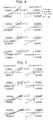
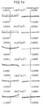
- Fig. 6 is a part of an aberrational diagram illustrating lateral aberrations in the ocular optical system according to Example 1 of the present invention.
- Fig. 7 is another part of the aberrational diagram illustrating lateral aberrations in the ocular optical system according to Example 1 of the present invention.
- Fig. 8 is the other part of the aberrational diagram illustrating lateral aberrations in the ocular optical system according to Example 1 of the present invention.
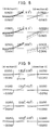
- Fig. 9 is a part of an aberrational diagram illustrating lateral aberrations in the ocular optical system according to Example 2 of the present invention.
- Fig. 10 is another part of the aberrational diagram illustrating lateral aberrations in the ocular optical system according to Example 2 of the present invention.
- Fig. 11 is the other part of the aberrational diagram illustrating lateral aberrations in the ocular optical system according to Example 2 of the present invention.
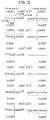
- Fig. 12 is an aberrational diagram illustrating lateral aberrations in the ocular optical system according to Example 3 of the present invention.
- Fig. 13 is an aberrational diagram illustrating lateral aberrations in the ocular optical system according to Example 4 of the present invention.
- Fig. 14 is an aberrational diagram illustrating lateral aberrations in the ocular optical system according to Example 5 of the present invention.
- Fig. 15 is a sectional view showing one example of an ocular optical system to which the present invention can be applied.
- Fig. 16 is a sectional view showing another example of an ocular optical system to which the present invention can be applied.
- Fig. 17 is a sectional view showing another example of an ocular optical system to which the present invention can be applied.
- Fig. 18 is a sectional view showing another example of an ocular optical system to which the present invention can be applied.
- Fig. 19 is a sectional view showing another example of an ocular optical system to which the present invention can be applied.
- Fig. 20 is a sectional view showing another example of an ocular optical system to which the present invention can be applied.
- Fig. 21 is a sectional view showing another example of an ocular optical system to which the present invention can be applied.
- Fig. 22 is a sectional view showing another example of an ocular optical system to which the present invention can be applied.
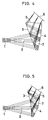
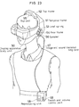
- Fig. 23 shows the whole arrangement of one example of a head-mounted image display apparatus according to the present invention.
- Figs. 24(a) and 24(b) show an optical system of a conventional head-mounted image display apparatus.
- Fig. 25 shows an optical system of another conventional head-mounted image display apparatus.
- Figs. 26(a) and 26(b) each show an optical system of still another conventional head-mounted image display apparatus.
- Fig. 27 shows an optical system of a further conventional head-mounted image display apparatus.
- Fig. 28 shows an optical system of a still further conventional head-mounted image display apparatus.
- an exit pupil 1 of an ocular optical system 7 is defined as the origin of an optical system
- an optical axis 2 is defined by a light ray which emanates from the center of the display area of an image display device 6 and passes through the center (the origin) of the exit pupil 1.
- a Z-axis is taken in a direction in which light rays travel from the exit pupil 1 along the optical axis 2.
- a Y-axis is taken in a direction which extends through the center of the exit pupil 1 at right angles to the Z-axis in a plane in which light rays are bent by the ocular optical system 7.
- An X-axis is taken in a direction which extends through the center of the exit pupil 1 at right angles to both the Z- and Y-axes.
- a direction in which the Z-axis extends from the exit pupil 1 toward the ocular optical system 7 is defined as a positive direction of the Z-axis.
- a direction in which the Y-axis extends from the optical axis 2 toward the image display device 6 is defined as a positive direction of the Y-axis.
- a direction in which the X-axis constitutes a right-handed system in combination with the Z- and Y-axes is defined as a positive direction of the X-axis. It should be noted that ray tracing is carried out by backward tracing from the exit pupil 1 of the ocular optical system 7, which is defined as the object side, toward the image display device 6, which is defined as the image surface side.
- the eccentricity Y is a distance by which the surface deviates in the Y-axis direction from the exit pupil 1, which is the origin of the optical system
- the eccentricity Z is a distance by which the surface deviates in the Z-axis direction from the exit pupil 1
- the amount of inclination ⁇ is an angle of tilt with respect to the Z-axis.
- the counterclockwise direction is defined as a positive direction. It should be noted that the surface separation in the constituent parameters is meaningless.
- the configuration of an anamorphic surface is defined by the following equation.
- a straight line which passes through the origin of the surface configuration, and which is perpendicular to the optical surface is defined as the axis of the anamorphic surface.
- Z is the amount of deviation from a plane tangent to the origin of the surface configuration
- CX is the curvature in the X-axis direction
- CY is the curvature in the Y-axis direction
- K x is the conical coefficient in the X-axis direction
- K y is the conical coefficient in the Y-axis direction
- R n is the rotationally
- the term concerning an aspherical surface for which no data is shown is 0.
- the refractive index is expressed by the refractive index for the spectral d-line (wavelength: 587.56 nm). Lengths are given in millimeters.
- the ocular optical system 7 in any of the following Examples 1 to 6 has three surfaces, i.e. a first surface 3, a second surface 4, and a third surface 5, and a space lying between these surfaces is filled with a medium having a refractive index larger than 1.
- Display light from an image display device 6 enters the optical system 7 through the third surface 5, which is a transparent surface disposed to face the image display device 6.
- the incident light is reflected by the first surface 3, which is disposed on the optical axis 2 between the second surface 4 and the exit pupil 1.
- the reflected light is reflected by the second surface 4, which is a reflecting surface eccentrically disposed on the optical axis 2 to face the exit pupil 1.
- Figs. 1 to 5 are sectional views of Examples 1 to 5, taken along the YZ-plane containing the optical axis 2. Illustration of Example 6 is omitted. Constituent parameters in Examples 1 to 6 will be shown later.
- both the first and second surfaces 3 and 4 are anamorphic surfaces defined by the above equation (b), and the third surface 5 is a plane surface.
- the first, second and third surfaces 3, 4 and 5 are all three-dimensional surfaces defined by the above equation (a).
- the first surface 3 is a plane surface
- both the second and third surfaces 4 and 5 are three-dimensional surfaces defined by the equation (a).
- Example 5 the first surface 3 is a spherical surface, and both the second and third surfaces 4 and 5 are three-dimensional surfaces defined by the equation (a).
- the horizontal field angle is 57.8 o
- the vertical field angle is 34.5 o
- the pupil diameter is 4 millimeters.
- the horizontal field angle is 40 o
- the vertical field angle is 30.5 o
- the pupil diameter is 8 millimeters.
- the horizontal field angle is 40 o
- the vertical field angle is 30.5 o
- the pupil diameter is 4 millimeters.
- the horizontal field angle is 35 o
- the vertical field angle is 26.6 o
- the pupil diameter is 4 millimeters.
- the horizontal field angle is 30 o
- the vertical field angle is 22.7 o
- the pupil diameter is 4 millimeters.
- ocular optical systems in the above examples are formed by using three-dimensional surfaces defined by the equation (a) and anamorphic surfaces defined by the equation (b), curved surfaces defined by any defining equation can be used in the present invention. No matter which defining equation is used, an ocular optical system which is considerably favorably corrected for aberrations can be obtained by satisfying any or some of the conditions shown in the present invention. It should be noted that conditional expressions which are used in conventional non-decentered systems, e.g.
- a portable image display apparatus such as a stationary or head-mounted image display apparatus, which enables the observer to see with both eyes by preparing a pair of combinations of an ocular optical system according to the present invention, arranged as described above, and an image display device for the left and right eyes, and supporting them apart from each other by the distance between the eyes.
- Fig. 23 shows the whole arrangement of an example of such a portable image display apparatus.
- a display apparatus body unit 50 contains a pair of left and right ocular optical systems such as those described above, and image display devices comprising liquid crystal display devices are disposed at the respective image planes of the two ocular optical systems.
- the apparatus body unit 50 is provided with a pair of left and right temporal frames 51 which are contiguous with the left and right ends of the apparatus body unit 50, as illustrated in the figure.
- the two temporal frames 51 are connected by a top frame 52.
- a rear frame 54 is attached to the intermediate portion of each temporal frame 51 through a leaf spring 53.
- a top pad 55 which is an elastic material such as a sponge, is attached to the inner side of the top frame 52, and a similar pad is attached to the inner side of each rear frame 54, thereby allowing the user to wear the display apparatus on his or her head without feeling uncomfortable.
- a speaker 56 is provided on each rear frame 54 to enable the user to enjoy listening to stereophonic sound in addition to image observation.
- the display apparatus body unit 50 having the speakers 56 is connected with a reproducing unit 58, e.g. a portable video cassette unit, through an image and sound transmitting cord 57. Therefore, the user can enjoy not only observing an image but also listening to sound with the reproducing unit 58 retained on a desired position, e.g. a belt, as illustrated in the figure.
- Reference numeral 59 in the figure denotes a switch and volume control part of the reproducing unit 58.
- the top frame 52 contains electronic parts such as image and sound processing circuits.
- the cord 57 may have a jack and plug arrangement attached to the distal end thereof so that the cord 57 can be detachably connected to an existing video deck.
- the cord 57 may also be connected to a TV signal receiving tuner so as to enable the user to enjoy watching TV.
- the cord 57 may be connected to a computer to receive computer graphic images or message images or the like from the computer.
- the image display apparatus may be arranged to receive external radio signals through an antenna connected thereto.
- the present invention makes it possible to provide a head-mounted image display apparatus capable of providing an observation image which is clear and has minimal distortion even at a wide field angle.
- a head-mounted image display apparatus capable of providing an observation image which is clear and has minimal distortion even at a wide field angle.
- the apparatus has an image display device (6), and an ocular optical system (7) for leading an image formed by the image display device (6) to an observer's eyeball position without forming an intermediate image so that the image can be observed as a virtual image.
- the ocular optical system (7) has at least one reflecting surface (4) having reflecting action.
- the at least one reflecting surface (4) has a surface configuration defined by a plane-symmetry three-dimensional surface which has no axis of rotational symmetry in nor out of the surface, and which has only one plane of symmetry.
Landscapes
- Physics & Mathematics (AREA)
- General Physics & Mathematics (AREA)
- Optics & Photonics (AREA)
- Lenses (AREA)
Applications Claiming Priority (9)
| Application Number | Priority Date | Filing Date | Title |
|---|---|---|---|
| JP09230196A JP3683339B2 (ja) | 1996-04-15 | 1996-04-15 | 頭部装着型画像表示装置 |
| JP92301/96 | 1996-04-15 | ||
| JP92299/96 | 1996-04-15 | ||
| JP9230096 | 1996-04-15 | ||
| JP9229996 | 1996-04-15 | ||
| JP9230196 | 1996-04-15 | ||
| JP09230096A JP3683338B2 (ja) | 1996-04-15 | 1996-04-15 | 頭部装着型画像表示装置 |
| JP09229996A JP3683337B2 (ja) | 1996-04-15 | 1996-04-15 | 頭部装着型画像表示装置 |
| JP92300/96 | 1996-04-15 |
Publications (3)
| Publication Number | Publication Date |
|---|---|
| EP0802440A2 true EP0802440A2 (de) | 1997-10-22 |
| EP0802440A3 EP0802440A3 (de) | 1998-12-09 |
| EP0802440B1 EP0802440B1 (de) | 2005-06-22 |
Family
ID=27306990
Family Applications (1)
| Application Number | Title | Priority Date | Filing Date |
|---|---|---|---|
| EP96112994A Expired - Lifetime EP0802440B1 (de) | 1996-04-15 | 1996-08-13 | Am Kopf montierter Bildanzeigeapparat |
Country Status (3)
| Country | Link |
|---|---|
| US (1) | US5959780A (de) |
| EP (1) | EP0802440B1 (de) |
| DE (1) | DE69634874D1 (de) |
Cited By (2)
| Publication number | Priority date | Publication date | Assignee | Title |
|---|---|---|---|---|
| EP0977067A3 (de) * | 1998-07-29 | 2000-05-31 | Canon Kabushiki Kaisha | Optisches System |
| WO2014189692A2 (en) | 2013-05-24 | 2014-11-27 | University Of Rochester | Optical display apparatus, method, and applications |
Families Citing this family (51)
| Publication number | Priority date | Publication date | Assignee | Title |
|---|---|---|---|---|
| JPH10239630A (ja) * | 1996-12-24 | 1998-09-11 | Olympus Optical Co Ltd | 画像表示装置 |
| JP2000098232A (ja) * | 1998-09-25 | 2000-04-07 | Canon Inc | 光学素子及びそれを用いた光学系 |
| US6417970B1 (en) | 2000-06-08 | 2002-07-09 | Interactive Imaging Systems | Two stage optical system for head mounted display |
| US6522474B2 (en) | 2001-06-11 | 2003-02-18 | Eastman Kodak Company | Head-mounted optical apparatus for stereoscopic display |
| JP3755036B2 (ja) * | 2002-09-02 | 2006-03-15 | 国立大学法人大阪大学 | 広視野角ヘッドマウントディスプレイ装置 |
| DE50305854D1 (de) | 2003-09-03 | 2007-01-11 | Zeiss Carl | HMD-Vorrichtung (Head Mounted Display) mit einer eine asphärische Fläche aufweisenden Abbildungsoptik |
| DE102007015278A1 (de) * | 2007-03-29 | 2008-10-02 | Carl Zeiss Ag | Optisches Okularsystem |
| CA2712059A1 (en) | 2008-01-22 | 2009-07-30 | The Arizona Board Of Regents On Behalf Of The University Of Arizona | Head-mounted projection display using reflective microdisplays |
| CN101359089B (zh) * | 2008-10-08 | 2010-08-11 | 北京理工大学 | 轻小型大视场自由曲面棱镜头盔显示器光学系统 |
| WO2010123934A1 (en) * | 2009-04-20 | 2010-10-28 | The Arizona Board Of Regents On Behalf Of The University Of Arizona | Optical see-through free-form head-mounted display |
| US20110075257A1 (en) | 2009-09-14 | 2011-03-31 | The Arizona Board Of Regents On Behalf Of The University Of Arizona | 3-Dimensional electro-optical see-through displays |
| US10180572B2 (en) | 2010-02-28 | 2019-01-15 | Microsoft Technology Licensing, Llc | AR glasses with event and user action control of external applications |
| US9091851B2 (en) | 2010-02-28 | 2015-07-28 | Microsoft Technology Licensing, Llc | Light control in head mounted displays |
| US9128281B2 (en) | 2010-09-14 | 2015-09-08 | Microsoft Technology Licensing, Llc | Eyepiece with uniformly illuminated reflective display |
| US8467133B2 (en) | 2010-02-28 | 2013-06-18 | Osterhout Group, Inc. | See-through display with an optical assembly including a wedge-shaped illumination system |
| US20120249797A1 (en) | 2010-02-28 | 2012-10-04 | Osterhout Group, Inc. | Head-worn adaptive display |
| US9285589B2 (en) | 2010-02-28 | 2016-03-15 | Microsoft Technology Licensing, Llc | AR glasses with event and sensor triggered control of AR eyepiece applications |
| WO2011106797A1 (en) * | 2010-02-28 | 2011-09-01 | Osterhout Group, Inc. | Projection triggering through an external marker in an augmented reality eyepiece |
| US9229227B2 (en) | 2010-02-28 | 2016-01-05 | Microsoft Technology Licensing, Llc | See-through near-eye display glasses with a light transmissive wedge shaped illumination system |
| US9223134B2 (en) | 2010-02-28 | 2015-12-29 | Microsoft Technology Licensing, Llc | Optical imperfections in a light transmissive illumination system for see-through near-eye display glasses |
| US8482859B2 (en) | 2010-02-28 | 2013-07-09 | Osterhout Group, Inc. | See-through near-eye display glasses wherein image light is transmitted to and reflected from an optically flat film |
| US8488246B2 (en) | 2010-02-28 | 2013-07-16 | Osterhout Group, Inc. | See-through near-eye display glasses including a curved polarizing film in the image source, a partially reflective, partially transmitting optical element and an optically flat film |
| US20150309316A1 (en) | 2011-04-06 | 2015-10-29 | Microsoft Technology Licensing, Llc | Ar glasses with predictive control of external device based on event input |
| US9759917B2 (en) | 2010-02-28 | 2017-09-12 | Microsoft Technology Licensing, Llc | AR glasses with event and sensor triggered AR eyepiece interface to external devices |
| US9182596B2 (en) | 2010-02-28 | 2015-11-10 | Microsoft Technology Licensing, Llc | See-through near-eye display glasses with the optical assembly including absorptive polarizers or anti-reflective coatings to reduce stray light |
| US9129295B2 (en) | 2010-02-28 | 2015-09-08 | Microsoft Technology Licensing, Llc | See-through near-eye display glasses with a fast response photochromic film system for quick transition from dark to clear |
| US8472120B2 (en) | 2010-02-28 | 2013-06-25 | Osterhout Group, Inc. | See-through near-eye display glasses with a small scale image source |
| US9366862B2 (en) | 2010-02-28 | 2016-06-14 | Microsoft Technology Licensing, Llc | System and method for delivering content to a group of see-through near eye display eyepieces |
| US8477425B2 (en) | 2010-02-28 | 2013-07-02 | Osterhout Group, Inc. | See-through near-eye display glasses including a partially reflective, partially transmitting optical element |
| US9097891B2 (en) | 2010-02-28 | 2015-08-04 | Microsoft Technology Licensing, Llc | See-through near-eye display glasses including an auto-brightness control for the display brightness based on the brightness in the environment |
| US9341843B2 (en) | 2010-02-28 | 2016-05-17 | Microsoft Technology Licensing, Llc | See-through near-eye display glasses with a small scale image source |
| US9134534B2 (en) | 2010-02-28 | 2015-09-15 | Microsoft Technology Licensing, Llc | See-through near-eye display glasses including a modular image source |
| US9097890B2 (en) | 2010-02-28 | 2015-08-04 | Microsoft Technology Licensing, Llc | Grating in a light transmissive illumination system for see-through near-eye display glasses |
| CN102782562B (zh) | 2010-04-30 | 2015-07-22 | 北京理工大学 | 宽视场高分辨率拼接式头盔显示装置 |
| NZ706893A (en) | 2010-12-24 | 2017-02-24 | Magic Leap Inc | An ergonomic head mounted display device and optical system |
| JP6141584B2 (ja) | 2012-01-24 | 2017-06-07 | アリゾナ ボード オブ リージェンツ オン ビハーフ オブ ザ ユニバーシティ オブ アリゾナ | 小型視線追従型ヘッドマウントディスプレイ |
| WO2014043142A1 (en) | 2012-09-11 | 2014-03-20 | Augmented Vision, Inc. | Compact eye imaging and eye tracking apparatus |
| JP5903018B2 (ja) * | 2012-09-26 | 2016-04-13 | ソニー株式会社 | ヘッドマウントディスプレイ |
| CA3102710A1 (en) | 2012-10-18 | 2014-04-24 | The Arizona Board Of Regents On Behalf Of The University Of Arizona | Stereoscopic displays with addressable focus cues |
| KR102539365B1 (ko) | 2014-03-05 | 2023-06-01 | 아리조나 보드 오브 리전츠 온 비해프 오브 더 유니버시티 오브 아리조나 | 가변 초점 및/또는 객체 인식 기능을 가진 웨어러블 3d 증강 현실 디스플레이 |
| US10176961B2 (en) | 2015-02-09 | 2019-01-08 | The Arizona Board Of Regents On Behalf Of The University Of Arizona | Small portable night vision system |
| KR20160147636A (ko) | 2015-06-15 | 2016-12-23 | 삼성전자주식회사 | 헤드 마운티드 디스플레이 장치 |
| WO2016204433A1 (en) | 2015-06-15 | 2016-12-22 | Samsung Electronics Co., Ltd. | Head mounted display apparatus |
| US10739578B2 (en) | 2016-08-12 | 2020-08-11 | The Arizona Board Of Regents On Behalf Of The University Of Arizona | High-resolution freeform eyepiece design with a large exit pupil |
| CA3034713C (en) * | 2016-08-12 | 2024-07-02 | Gentex Corporation | Portable near-eye vision systems with large exit pupils using lible shaped eyepieces |
| US10402950B1 (en) * | 2016-11-15 | 2019-09-03 | Facebook Technologies, Llc | Optical measurement system |
| CA3055545A1 (en) | 2017-03-09 | 2018-09-13 | Arizona Board Of Regents On Behalf Of The University Of Arizona | Head-mounted light field display with integral imaging and waveguide prism |
| AU2018231081B2 (en) | 2017-03-09 | 2023-03-09 | Arizona Board Of Regents On Behalf Of The University Of Arizona | Head-mounted light field display with integral imaging and relay optics |
| JP6516806B2 (ja) * | 2017-08-31 | 2019-05-22 | キヤノン株式会社 | 画像表示装置 |
| JP7185331B2 (ja) | 2018-03-22 | 2022-12-07 | アリゾナ ボード オブ リージェンツ オン ビハーフ オブ ザ ユニバーシティ オブ アリゾナ | インテグラルイメージング方式のライトフィールドディスプレイ用にライトフィールド画像をレンダリングする方法 |
| WO2021068855A1 (zh) | 2019-10-10 | 2021-04-15 | 华为技术有限公司 | 一种显示设备模组及头戴式显示设备 |
Family Cites Families (15)
| Publication number | Priority date | Publication date | Assignee | Title |
|---|---|---|---|---|
| US3836931A (en) * | 1971-11-11 | 1974-09-17 | Polaroid Corp | Eye lens in a single lens reflex camera viewfinder providing field tilt compensation |
| US4021846A (en) * | 1972-09-25 | 1977-05-03 | The United States Of America As Represented By The Secretary Of The Navy | Liquid crystal stereoscopic viewer |
| US4961625A (en) * | 1987-09-18 | 1990-10-09 | Flight Dynamics, Inc. | Automobile head-up display system with reflective aspheric surface |
| US5274406A (en) * | 1987-12-29 | 1993-12-28 | Asahi Kogaku Kogyo Kabushiki Kaisha | Image projecting device |
| US5325386A (en) * | 1992-04-21 | 1994-06-28 | Bandgap Technology Corporation | Vertical-cavity surface emitting laser assay display system |
| JP3155360B2 (ja) * | 1992-07-27 | 2001-04-09 | オリンパス光学工業株式会社 | 視覚表示装置 |
| US5585813A (en) * | 1992-10-05 | 1996-12-17 | Rockwell International Corporation | All aspect head aiming display |
| US5357369A (en) * | 1992-12-21 | 1994-10-18 | Geoffrey Pilling | Wide-field three-dimensional viewing system |
| JP3245478B2 (ja) * | 1993-04-27 | 2002-01-15 | オリンパス光学工業株式会社 | 頭部装着式表示装置 |
| US5585967A (en) * | 1993-09-07 | 1996-12-17 | The Walt Disney Company | Three dimensional virtual image system |
| JPH07325266A (ja) * | 1994-06-01 | 1995-12-12 | Olympus Optical Co Ltd | 映像表示装置 |
| EP0687932B1 (de) * | 1994-06-13 | 2005-05-25 | Canon Kabushiki Kaisha | Anzeigevorrichtung |
| JP3658034B2 (ja) * | 1995-02-28 | 2005-06-08 | キヤノン株式会社 | 画像観察光学系及び撮像光学系 |
| JP3599828B2 (ja) * | 1995-05-18 | 2004-12-08 | オリンパス株式会社 | 光学装置 |
| JPH09219832A (ja) * | 1996-02-13 | 1997-08-19 | Olympus Optical Co Ltd | 画像表示装置 |
-
1996
- 1996-04-23 US US08/636,592 patent/US5959780A/en not_active Expired - Lifetime
- 1996-08-13 DE DE69634874T patent/DE69634874D1/de not_active Expired - Lifetime
- 1996-08-13 EP EP96112994A patent/EP0802440B1/de not_active Expired - Lifetime
Cited By (4)
| Publication number | Priority date | Publication date | Assignee | Title |
|---|---|---|---|---|
| EP0977067A3 (de) * | 1998-07-29 | 2000-05-31 | Canon Kabushiki Kaisha | Optisches System |
| WO2014189692A2 (en) | 2013-05-24 | 2014-11-27 | University Of Rochester | Optical display apparatus, method, and applications |
| EP3004965A4 (de) * | 2013-05-24 | 2016-05-25 | Univ Rochester | Optische anzeigevorrichtung, verfahren und anwendungen |
| US10088681B2 (en) | 2013-05-24 | 2018-10-02 | University Of Rochester | Optical display apparatus, method, and applications |
Also Published As
| Publication number | Publication date |
|---|---|
| US5959780A (en) | 1999-09-28 |
| EP0802440B1 (de) | 2005-06-22 |
| EP0802440A3 (de) | 1998-12-09 |
| DE69634874D1 (de) | 2005-07-28 |
Similar Documents
| Publication | Publication Date | Title |
|---|---|---|
| EP0802440A2 (de) | Am Kopf montierter Bildanzeigeapparat | |
| US5986812A (en) | Image display apparatus | |
| US6028709A (en) | Image display apparatus | |
| US6097542A (en) | Optical system having reflecting surface of non-rotationally symmetric surface configuration | |
| US5991103A (en) | Prism optical system | |
| US6008778A (en) | Visual display apparatus | |
| US6097354A (en) | Image display apparatus | |
| US6134051A (en) | Optical system for image observation | |
| USRE37175E1 (en) | Image display apparatus | |
| US6333820B1 (en) | Image display apparatus | |
| US6195207B1 (en) | Head or face mounted image display apparatus | |
| EP0845692B1 (de) | Optisches System mit einer rotationsasymmetrischengewölbten Fläche | |
| US5436765A (en) | Visual display apparatus | |
| US6760169B2 (en) | Prism optical element, image observation apparatus and image display apparatus | |
| KR100412760B1 (ko) | 헤드마운트디스플레이장치및이장치에이용되는디스플레이용광학계 | |
| US6342871B1 (en) | Image display apparatus | |
| US6130784A (en) | Resolution enhancing image display apparatus | |
| US5923477A (en) | Image display apparatus having a reflecting surface that bends light rays | |
| EP0857992B1 (de) | Optisches System mit dezentriertem Prisma | |
| US5748378A (en) | Image display apparatus | |
| JPH06294943A (ja) | 視覚表示装置 | |
| KR19990077356A (ko) | 표시장치 | |
| JPH07191274A (ja) | 画像表示装置 | |
| JP3683338B2 (ja) | 頭部装着型画像表示装置 | |
| JPH10206790A (ja) | 表示装置 |
Legal Events
| Date | Code | Title | Description |
|---|---|---|---|
| PUAI | Public reference made under article 153(3) epc to a published international application that has entered the european phase |
Free format text: ORIGINAL CODE: 0009012 |
|
| AK | Designated contracting states |
Kind code of ref document: A2 Designated state(s): DE FR GB |
|
| PUAL | Search report despatched |
Free format text: ORIGINAL CODE: 0009013 |
|
| AK | Designated contracting states |
Kind code of ref document: A3 Designated state(s): DE FR GB |
|
| 17P | Request for examination filed |
Effective date: 19990608 |
|
| 17Q | First examination report despatched |
Effective date: 20030820 |
|
| RAP1 | Party data changed (applicant data changed or rights of an application transferred) |
Owner name: OLYMPUS CORPORATION |
|
| GRAP | Despatch of communication of intention to grant a patent |
Free format text: ORIGINAL CODE: EPIDOSNIGR1 |
|
| GRAS | Grant fee paid |
Free format text: ORIGINAL CODE: EPIDOSNIGR3 |
|
| GRAA | (expected) grant |
Free format text: ORIGINAL CODE: 0009210 |
|
| AK | Designated contracting states |
Kind code of ref document: B1 Designated state(s): DE FR GB |
|
| REG | Reference to a national code |
Ref country code: GB Ref legal event code: FG4D |
|
| REF | Corresponds to: |
Ref document number: 69634874 Country of ref document: DE Date of ref document: 20050728 Kind code of ref document: P |
|
| PG25 | Lapsed in a contracting state [announced via postgrant information from national office to epo] |
Ref country code: GB Free format text: LAPSE BECAUSE OF NON-PAYMENT OF DUE FEES Effective date: 20050922 |
|
| PG25 | Lapsed in a contracting state [announced via postgrant information from national office to epo] |
Ref country code: DE Free format text: LAPSE BECAUSE OF FAILURE TO SUBMIT A TRANSLATION OF THE DESCRIPTION OR TO PAY THE FEE WITHIN THE PRESCRIBED TIME-LIMIT Effective date: 20050923 |
|
| ET | Fr: translation filed | ||
| PG25 | Lapsed in a contracting state [announced via postgrant information from national office to epo] |
Ref country code: FR Free format text: LAPSE BECAUSE OF NON-PAYMENT OF DUE FEES Effective date: 20060428 |
|
| PLBE | No opposition filed within time limit |
Free format text: ORIGINAL CODE: 0009261 |
|
| STAA | Information on the status of an ep patent application or granted ep patent |
Free format text: STATUS: NO OPPOSITION FILED WITHIN TIME LIMIT |
|
| GBPC | Gb: european patent ceased through non-payment of renewal fee |
Effective date: 20050922 |
|
| REG | Reference to a national code |
Ref country code: FR Ref legal event code: ST Effective date: 20060428 |
|
| 26N | No opposition filed |
Effective date: 20060323 |