EP0802163B1 - Wasserbehandlung durch UV-Bestrahlung und Filtration - Google Patents
Wasserbehandlung durch UV-Bestrahlung und Filtration Download PDFInfo
- Publication number
- EP0802163B1 EP0802163B1 EP97302591A EP97302591A EP0802163B1 EP 0802163 B1 EP0802163 B1 EP 0802163B1 EP 97302591 A EP97302591 A EP 97302591A EP 97302591 A EP97302591 A EP 97302591A EP 0802163 B1 EP0802163 B1 EP 0802163B1
- Authority
- EP
- European Patent Office
- Prior art keywords
- water
- unit
- cover
- container
- filtration
- Prior art date
- Legal status (The legal status is an assumption and is not a legal conclusion. Google has not performed a legal analysis and makes no representation as to the accuracy of the status listed.)
- Expired - Lifetime
Links
- XLYOFNOQVPJJNP-UHFFFAOYSA-N water Substances O XLYOFNOQVPJJNP-UHFFFAOYSA-N 0.000 title claims description 63
- 238000001914 filtration Methods 0.000 title claims description 30
- 238000009281 ultraviolet germicidal irradiation Methods 0.000 title 1
- 230000005855 radiation Effects 0.000 claims description 22
- 239000000463 material Substances 0.000 claims description 13
- 241000195493 Cryptophyta Species 0.000 claims description 6
- 238000005192 partition Methods 0.000 claims description 6
- 230000002093 peripheral effect Effects 0.000 claims description 6
- 239000005030 aluminium foil Substances 0.000 claims description 3
- 238000004140 cleaning Methods 0.000 claims description 3
- 239000004033 plastic Substances 0.000 claims description 3
- 229920003023 plastic Polymers 0.000 claims description 3
- 230000008030 elimination Effects 0.000 claims description 2
- 238000003379 elimination reaction Methods 0.000 claims description 2
- 239000011521 glass Substances 0.000 claims description 2
- 230000007547 defect Effects 0.000 claims 1
- 239000010453 quartz Substances 0.000 description 4
- VYPSYNLAJGMNEJ-UHFFFAOYSA-N silicon dioxide Inorganic materials O=[Si]=O VYPSYNLAJGMNEJ-UHFFFAOYSA-N 0.000 description 4
- QGZKDVFQNNGYKY-UHFFFAOYSA-N Ammonia Chemical compound N QGZKDVFQNNGYKY-UHFFFAOYSA-N 0.000 description 2
- IOVCWXUNBOPUCH-UHFFFAOYSA-M Nitrite anion Chemical compound [O-]N=O IOVCWXUNBOPUCH-UHFFFAOYSA-M 0.000 description 1
- 229910021529 ammonia Inorganic materials 0.000 description 1
- 238000000354 decomposition reaction Methods 0.000 description 1
- 229920001971 elastomer Polymers 0.000 description 1
- 229920001821 foam rubber Polymers 0.000 description 1
- 231100001261 hazardous Toxicity 0.000 description 1
- 239000012535 impurity Substances 0.000 description 1
- 230000000149 penetrating effect Effects 0.000 description 1
- 230000000630 rising effect Effects 0.000 description 1
- 230000000007 visual effect Effects 0.000 description 1
Images
Classifications
-
- A—HUMAN NECESSITIES
- A01—AGRICULTURE; FORESTRY; ANIMAL HUSBANDRY; HUNTING; TRAPPING; FISHING
- A01K—ANIMAL HUSBANDRY; AVICULTURE; APICULTURE; PISCICULTURE; FISHING; REARING OR BREEDING ANIMALS, NOT OTHERWISE PROVIDED FOR; NEW BREEDS OF ANIMALS
- A01K63/00—Receptacles for live fish, e.g. aquaria; Terraria
- A01K63/04—Arrangements for treating water specially adapted to receptacles for live fish
-
- C—CHEMISTRY; METALLURGY
- C02—TREATMENT OF WATER, WASTE WATER, SEWAGE, OR SLUDGE
- C02F—TREATMENT OF WATER, WASTE WATER, SEWAGE, OR SLUDGE
- C02F1/00—Treatment of water, waste water, or sewage
- C02F1/30—Treatment of water, waste water, or sewage by irradiation
- C02F1/32—Treatment of water, waste water, or sewage by irradiation with ultraviolet light
- C02F1/325—Irradiation devices or lamp constructions
-
- C—CHEMISTRY; METALLURGY
- C02—TREATMENT OF WATER, WASTE WATER, SEWAGE, OR SLUDGE
- C02F—TREATMENT OF WATER, WASTE WATER, SEWAGE, OR SLUDGE
- C02F2201/00—Apparatus for treatment of water, waste water or sewage
- C02F2201/32—Details relating to UV-irradiation devices
- C02F2201/322—Lamp arrangement
- C02F2201/3221—Lamps suspended above a water surface or pipe
-
- C—CHEMISTRY; METALLURGY
- C02—TREATMENT OF WATER, WASTE WATER, SEWAGE, OR SLUDGE
- C02F—TREATMENT OF WATER, WASTE WATER, SEWAGE, OR SLUDGE
- C02F2201/00—Apparatus for treatment of water, waste water or sewage
- C02F2201/32—Details relating to UV-irradiation devices
- C02F2201/322—Lamp arrangement
- C02F2201/3227—Units with two or more lamps
-
- C—CHEMISTRY; METALLURGY
- C02—TREATMENT OF WATER, WASTE WATER, SEWAGE, OR SLUDGE
- C02F—TREATMENT OF WATER, WASTE WATER, SEWAGE, OR SLUDGE
- C02F2201/00—Apparatus for treatment of water, waste water or sewage
- C02F2201/32—Details relating to UV-irradiation devices
- C02F2201/322—Lamp arrangement
- C02F2201/3228—Units having reflectors, e.g. coatings, baffles, plates, mirrors
Definitions
- This invention relates to a unit for eliminating algae in ornamental ponds.
- Apparatus for killing algae is known from GB 2264295 and comprises a container housing separate water radiation and filtration chambers having respectively an inlet and an outlet for passing water to be treated through the container, a weir for maintaining a predetermined water level in the radiation chamber, and a source of ultra-violet light suspended in the water radiation chamber.
- the present invention proceeds from the discovery that pond water can be treated satisfactorily by a source of ultra-violet light which is not immersed in the water being treated but rather suspended above it. This permits expensive shielding such as a quartz tube to be dispensed with and makes changing a gas-filled tube a much simpler and less hazardous operation.
- a unit for algae elimination in ornamental ponds is characterised in that said chambers are side-by-side and separated by a partition wall, the weir comprising a reduced-height portion of said wall, said portion being located at an opposite end of the filtration chambers to the outlet such that water flowing over it must pass along the length of the filtration chamber before reaching the outlet, the source of ultra-violet light being suspended above the maximum water level set by said weir in the water radiation chamber.
- the reduced-height portion of the wall increases in width vertically upwardly so that as the water level rises a greater volume of water is permitted to overflow the weir.
- At least one side of said cut out may have a stepped configuration.
- Said source of ultra-violet light is preferably mounted in a removable cover for the container, and a gap may be provided between upper edges of walls of the container and the cover, when the cover is positioned over the container, through which water may overflow in the event of failure to do so of said means for maintaining a normal water level in the container, such that in the event of such failure the water level is prevented from rising to the source of ultra-violet light.
- the source of ultra-violet light is an elongated gas-filled glass tube and the cover may have spaced apart, resilient mountings for opposite ends of the tube.
- a diffuser is preferably positioned within the container to deflect water entering the container through the inlet such as to prevent a linear flow of water through the container.
- the cover is in two parts a first of which extends over the radiation chamber and is secured by screws so that it cannot be removed inadvertently and the second of which extends over the filtration chamber and is hinged to give ready access to the filtration chamber.
- the first part of the cover is preferably of inverted channel section, having an outwardly-extending peripheral flange at the free ends of the walls of the channel and there may be provided within the first part of the cover a lamp mounting also of inverted channel section but shallower than the channel of the cover, the mounting also having at the free ends of its walls an outwardly-extending peripheral flange and the arrangement being such that the flanges of the cover part and of the lamp mounting may be secured by common screws to top edges of the walls of the housing.
- the lamp mounting may be of a light-reflective material such as of a plastics material covered by an aluminium foil reflector.
- the bottom of the filtration chamber may be covered by a layer of a particulate biological filtration medium and said layer of particulate biological filtration medium may be covered by a layer of sponge-like material the upwardly presented surface of which undulates between peaks and troughs to maximise the surface area of the sponge-like material over which water in the filtration chamber will pass.
- the layer of sponge-like material may be integral so as to be removable in one piece, e.g. for cleaning, after opening the hinged part of the cover.
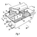
- the pond water filtration unit 10 shown comprises an open-topped, trough-like housing 11 having side walls 12 and 13 and end walls 14 and 15 upstanding from a bottom 16.
- a partition wall 17 extends between the end walls 14 and 15 in spaced relation to the side walls 12 and 13 so as to divide the interior of the housing into a radiation chamber 18 and a filtration chamber 19.
- Penetrating the end wall 14 is a water inlet 20 opening to a lower region of the radiation chamber 18 and a pair of water outlets 21 and 22 opening to a lower region of the filtration chamber 19.
- Suitable hoses (not shown) conduct water to be treated, e.g. from a pond, to the inlet 20 and return the treated water to the pond from the outlets 21 and 22.
- a suitable pump (not shown) is located on the inlet side to maintain a flow of water through inlet 20 into the housing 11.
- This cut away area has a lateral edge 24 of a stepped configuration. This provides graduations enabling a visual check to be made on the water level in the filtration chamber and moreover because the width of the weir increases upwardly it permits more water to flow over it as the water level rises. This will assist in maintaining a constant throughput of water and in preventing the chambers from over or underfilling.
- the weir 23 is at the end of the partition 17 remote from end wall 14, so that water flowing over it must pass along the whole length of the filtration chamber before reaching the outlets 21 and 22.
- the water to be treated is subjected to radiation from ultra violet lamps 25 and 26.
- the lamps, or each of them are unshielded for example by a quartz tube such as has hitherto been considered necessary to waterproof the light source in a water radiation system. Instead light from the lamps 25 and 26 passes directly to the water being treated.
- End fittings such as 27 and 28 for the lamp(s) penetrate opposite end walls of a mounting 29 of inverted channel section fabricated from a plastics material covered on the inner side with aluminium foil as a reflector.
- the lamps are supported by screws which pass through a plate 98 which is separated from the mounting 29 by a foam rubber layer 99.
- the mounting 29 has a peripheral flange 30 extending outwardly from the free ends of its four walls by which it rests on a number of small pillars 38 distributed around the side wall 12 and end walls 14 and 15 of the housing 11 and additionally two columns 31 and 32 upstanding from the bottom 16 of the housing.
- the partition 17 intersects these columns but is of lesser height.
- the housing 11 as a whole is lidded by a cover which is in two parts, one 33 of which extends over the radiation chamber 18 and the other 34 of which extends over the filtration chamber 19, where it is supported by more of the small pillars 38 above walls 13, 14 and 15..
- the cover part 34 is hinged at 35 to the cover part 33 so that it can be raised and lowered, without disturbing the cover part 33, to gain access to the filtration chamber 19.
- screws 36 must be undone.
- the apertures between the pillars 38 provide for emergency overflow of water from both chambers of the housing even when the cover part 33 is screwed in place and the cover part 34 is closed.
- the cover part 33 is of inverted channel section with a peripheral flange 38 extending outwardly from the free ends of its walls. In use the flange 38 extends over the flange of the lamp mounting 29 and is commonly secured by the screws 36.
- the channel of the cover part 33 is considerably deeper than the channel of the lamp mounting 29 with the result that a space exists between the two in which wiring, etc. for the lamp(s) can be accommodated.
- a barrier-like element 39 is located in the radiation chamber immediately in front of the inlet 20 to divert the incoming water and prevent an undesirable linear flow through the radiation chamber.
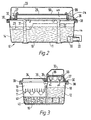
- the bottom of the filtration chamber is covered by a particulate biological filter medium 40.
- a layer 41 of sponge-like material such as a synthetic foamed rubber.
- the top surface of this layer 41 is undulant between peaks and troughs to maximise the surface area of the layer which is exposed to the water above and passing over it.
- the layer 41 is preferably provided by a single, integral piece of material which can be bodily removed for cleaning simply by hinging open the cover part 34.
Landscapes
- Life Sciences & Earth Sciences (AREA)
- Environmental Sciences (AREA)
- Toxicology (AREA)
- Biodiversity & Conservation Biology (AREA)
- Animal Husbandry (AREA)
- Health & Medical Sciences (AREA)
- Marine Sciences & Fisheries (AREA)
- Hydrology & Water Resources (AREA)
- Engineering & Computer Science (AREA)
- Environmental & Geological Engineering (AREA)
- Water Supply & Treatment (AREA)
- Chemical & Material Sciences (AREA)
- Organic Chemistry (AREA)
- Physical Water Treatments (AREA)
Claims (14)
- Einheit zur Algenbeseitigung in Zierwasserteichen, die einen Behälter (11) umfasst, der getrennte Wasserbestrahlungs- (18) und Filterkammern (19) mit jeweils einem Einlass (20) und einem Auslass (21, 22), um zu behandelndes Wasser durch den Behälter (11) zu leiten, ein Wehr (23) zum Aufrechterhalten eines festgelegten Wasserpegels in der Bestrahlungskammer (18) und eine Ultraviolettlichtquelle (25, 26) enthält, die in der Wasserbestrahlungskammer (18) aufgehängt ist, dadurch gekennzeichnet, dass die Kammern sich Seite an Seite befinden und durch eine Trennwand (17) getrennt sind, wobei das Wehr (23) einen Abschnitt der Wand (17) mit verminderter Höhe umfasst, wobei sich der Abschnitt an einem von dem Auslass (21, 22) entfernten Ende der Filterkammern (19) befindet, so dass Wasser, das darüber fließt, die Länge der Filterkammer passieren muss, bevor der Auslass (21, 22) erreicht wird, wobei die Ultraviolettlichtquelle (25, 26) über dem maximalen Wasserpegel liegt, der von dem Wehr (23) in der Wasserbestrahlungskammer (18) festgelegt ist.
- Einheit nach Anspruch 1, bei der der Abschnitt der Wand mit verminderter Höhe in der Breite vertikal nach oben zunimmt, so dass ein größeres Wasservolumen von der Bestrahlungskammer (18) über das Wehr in die Filterkammer (19) fließen kann, wenn der Wasserpegel steigt.
- Einheit nach Anspruch 2, bei der mindestens eine Seite des Abschnitts mit verminderter Höhe eine Stufenanordnung aufweist.
- Einheit nach einem der vorhergehenden Ansprüche, bei der die Ultraviolettlichtquelle (25-26) unter einer Abdeckung (33, 34) angebracht ist, die auf dem Behälter anbringbar ist, und wobei ein Spalt zwischen der Abdeckung (33, 34) und dem Behälter (11) vorhanden ist, durch den Wasser überfließen kann, falls der vorbestimmte Wasserpegel überschritten werden sollte.
- Einheit nach Anspruch 4, bei der die Abdeckung (33, 34) lösbar an dem Behälter (11) angebracht ist.
- Einheit nach Anspruch 5, bei der die Ultraviolettlichtquelle (25, 26) eine längliche gasgefüllte Glasröhre ist und die Abdeckung (33, 34) beabstandete, federnde Halterungen (29) für gegenüberliegende Enden der Lichtquelle (25, 26) aufweist.
- Einheit nach einem der vorhergehenden Ansprüche, bei der die Wasserführung durch den Behälter einen Wassereinlass (20) in einem unteren Bereich umfasst und ein Diffusor (39) in dem Behälter (11) angeordnet ist, um durch den Einlass (20) in den Behälter (11) eintretendes Wasser abzulenken, um ein lineares Fließen von Wasser durch den Behälter (11) zu verhindern.
- Einheit nach einem der vorhergehenden Ansprüche, bei der behandeltes Wasser aus der Filterkammer (19) durch einen Wasserauslass (21, 22) in einer von dem Wehr (23) beabstandeten Position abgezogen wird.
- Einheit nach einem der Ansprüche 4 bis 8, bei der die Abdeckung in zwei Teilen (33, 34) vorliegt, wobei das erste sich über der Bestrahlungskammer (18) erstreckt und durch Schrauben oder dergleichen befestigt ist, so dass es nicht versehentlich entfernt werden kann, und das zweite sich über der Filterkammer (19) erstreckt und mit Scharnieren versehen ist, so dass der Zugang zu der Filterkammer (19) leicht möglich ist.
- Einheit nach Anspruch 9, bei der das erste Teil der Abdeckung (33) einen umgekehrt U-förmigen Querschnitt mit sich nach auswärts erstreckendem peripherem Flansch (38) an den freien Enden der Wände der U-Form aufweist, und eine Lampenhalterung (29) in dem ersten Teil der Abdeckung (33) vorgesehen ist, die auch einen umgekehrt U-förmigen Querschnitt hat, der jedoch flacher als die U-Form der Abdeckung (33) ist, wobei die Halterung (29) ebenfalls an den freien Enden ihrer Wände einen sich nach auswärts erstreckenden peripheren Flansch aufweist, wobei die Anordnung derart ist, dass die Flansche des Abdeckteils (33) und der Lampenhalterung (29) durch gemeinsame Schrauben an oberen Rändern der Wände des Behälters (11) befestigt werden können.
- Einheit nach Anspruch 10, bei der die Lampenhalterung (29) aus lichtreflektierendem Material wie aus Kunststoffmaterial besteht, das mit einem Aluminiumfolienreflektor bedeckt ist.
- Einheit nach einem der vorhergehenden Ansprüche, bei der der Boden der Filterkammer (19) mit einer Schicht eines teilchenförmigen biologischen Filtermediums (40) bedeckt ist.
- Einheit nach Anspruch 12, bei der die Schicht aus teilchenförmigem biologischem Filtermedium (40) von einer Schicht aus schwammartigem Material bedeckt ist, dessen nach oben gerichtete Fläche wellenartig in Bergen und Tälern verläuft, um die Oberfläche des schwammartigen Materials zu vergrößern, über die das Wasser in der Filterkammer (19) geleitet wird.
- Einheit nach Anspruch 13, bei der die Schicht aus schwammartigem Material integral ausgebildet ist, damit sie in einem Stück, z. B. zur Reinigung, entfernbar ist, nachdem der mit Scharnieren versehene Teil der Abdeckung (34) geöffnet worden ist.
Applications Claiming Priority (3)
| Application Number | Priority Date | Filing Date | Title |
|---|---|---|---|
| GBGB9607843.1A GB9607843D0 (en) | 1996-04-16 | 1996-04-16 | Water treatment |
| GB9607843 | 1996-04-16 | ||
| US08/839,178 US5888388A (en) | 1996-04-16 | 1997-04-23 | Water treatment |
Publications (2)
| Publication Number | Publication Date |
|---|---|
| EP0802163A1 EP0802163A1 (de) | 1997-10-22 |
| EP0802163B1 true EP0802163B1 (de) | 2003-02-19 |
Family
ID=26309135
Family Applications (1)
| Application Number | Title | Priority Date | Filing Date |
|---|---|---|---|
| EP97302591A Expired - Lifetime EP0802163B1 (de) | 1996-04-16 | 1997-04-16 | Wasserbehandlung durch UV-Bestrahlung und Filtration |
Country Status (3)
| Country | Link |
|---|---|
| US (1) | US5888388A (de) |
| EP (1) | EP0802163B1 (de) |
| GB (2) | GB9607843D0 (de) |
Families Citing this family (14)
| Publication number | Priority date | Publication date | Assignee | Title |
|---|---|---|---|---|
| US6015229A (en) * | 1997-09-19 | 2000-01-18 | Calgon Carbon Corporation | Method and apparatus for improved mixing in fluids |
| US6193938B1 (en) * | 1999-03-17 | 2001-02-27 | Wedeco Ag Water Technology | Device for treating liquids with UV-radiation |
| US6683313B2 (en) * | 2000-09-14 | 2004-01-27 | Fujian Newland Entech Co., Ltd. | Ultraviolet water sterilization device in a modularized configuration |
| DE10131982A1 (de) * | 2001-07-02 | 2003-01-16 | Voith Paper Patent Gmbh | Verfahren und Vorrichtung zum Entgasen von Suspension, insbesondere Faserstoffsuspension |
| GB2389322B (en) | 2002-06-07 | 2005-08-17 | Baldwin Filters Inc | Environmentally friendly dual lube venturi filter cartridge |
| GB0218314D0 (en) * | 2002-08-07 | 2002-09-11 | Albagaia Ltd | Apparatus and method for treatment of chemical and biological hazards |
| RU2228299C1 (ru) * | 2003-03-19 | 2004-05-10 | Есиев Сергей Саладинович | Устройство водоподготовки |
| DE10318270B4 (de) * | 2003-04-22 | 2007-01-04 | Oase Gmbh | Durchlauffilter mit Schmutzkontrolle |
| GB2412950B (en) | 2004-06-10 | 2006-04-05 | Hozelock Ltd | A pump unit |
| EP2284127A1 (de) * | 2009-08-13 | 2011-02-16 | Koninklijke Philips Electronics N.V. | Vorrichtung mit einer Quelle zur Emission von ultraviolettem Licht |
| KR102222432B1 (ko) * | 2016-05-13 | 2021-03-04 | 엘지전자 주식회사 | 정수기 |
| USD817439S1 (en) * | 2016-08-19 | 2018-05-08 | Evoqua Water Technologies Llc | Modular electrochlorination enclosure |
| US11140882B2 (en) | 2018-05-30 | 2021-10-12 | Iwaki America Incorporated | Tank system and method |
| JP2020130033A (ja) * | 2019-02-19 | 2020-08-31 | 水作株式会社 | 濾過器付水槽セット |
Family Cites Families (15)
| Publication number | Priority date | Publication date | Assignee | Title |
|---|---|---|---|---|
| US2578414A (en) * | 1950-03-28 | 1951-12-11 | Gen Electric | Liquid irradiating apparatus |
| US3661262A (en) * | 1970-08-25 | 1972-05-09 | Oceanography Mariculture Ind | Filtration and circulation system for maintaining water quality in mariculture tank |
| GB1445799A (en) * | 1973-04-30 | 1976-08-11 | Foremost Mckesson | Reverse osmosis water demineralization device |
| US3971947A (en) * | 1974-12-19 | 1976-07-27 | Lambert Douglas N | Ultraviolet water purifier |
| DE2543418A1 (de) * | 1975-09-29 | 1977-04-07 | Stausberg | Verfahren zum entkeimen von wasser durch bestrahlung mit ultra-violettem licht und vorrichtung zur durchfuehrung des verfahrens |
| JPS588812B2 (ja) * | 1979-04-10 | 1983-02-17 | マルイ工業株式会社 | 魚類飼育水槽用水の浄化方法 |
| JPS6029557B2 (ja) * | 1979-04-20 | 1985-07-11 | 東洋電子興業株式会社 | 水殺菌装置 |
| JPS5735912A (en) * | 1980-08-11 | 1982-02-26 | Kuraray Co Ltd | Settling tank for activated sludge |
| DK163297C (da) * | 1990-02-08 | 1992-07-06 | Eskofot As | Fremgangsmaade og apparat til fjernelse af soelv i form af soelvsulfid fra en fotografisk vaeske ved bestraaling og udfaeldning |
| US5089137A (en) * | 1990-10-04 | 1992-02-18 | Mckown Gerard V | Gas-liquid contact sheet and packing material |
| US5227053A (en) * | 1990-11-30 | 1993-07-13 | Conventure Corporation | Water purification system |
| GB9111400D0 (en) * | 1991-05-25 | 1991-07-17 | Advisory Aquatic Centre Limite | Pond water biological treatment device |
| US5433866A (en) * | 1992-06-15 | 1995-07-18 | Hoppe; Jeffrey E. | System and method for treating water |
| GB2264295B (en) * | 1992-07-18 | 1995-05-03 | Uv Systems Limited | Water purification apparatus |
| US5653877A (en) * | 1992-12-09 | 1997-08-05 | Fm Mark Electronics Incorporated | Water purification system having multi-pass ultraviolet radiation and reverse osmosis chambers |
-
1996
- 1996-04-16 GB GBGB9607843.1A patent/GB9607843D0/en active Pending
-
1997
- 1997-04-16 EP EP97302591A patent/EP0802163B1/de not_active Expired - Lifetime
- 1997-04-16 GB GB9707663A patent/GB2309876B/en not_active Expired - Fee Related
- 1997-04-23 US US08/839,178 patent/US5888388A/en not_active Expired - Lifetime
Also Published As
| Publication number | Publication date |
|---|---|
| GB2309876B (en) | 1998-03-18 |
| GB9607843D0 (en) | 1996-06-19 |
| GB9707663D0 (en) | 1997-06-04 |
| EP0802163A1 (de) | 1997-10-22 |
| US5888388A (en) | 1999-03-30 |
| GB2309876A (en) | 1997-08-06 |
Similar Documents
| Publication | Publication Date | Title |
|---|---|---|
| EP0802163B1 (de) | Wasserbehandlung durch UV-Bestrahlung und Filtration | |
| US3971947A (en) | Ultraviolet water purifier | |
| US8507874B2 (en) | Fluid treatment system | |
| US5624573A (en) | Apparatus for the disinfection of a flowing liquid medium and a plant for the treatment of clarified sewage | |
| ES2334996T3 (es) | Dispositivo de sedimentacion. | |
| EP1515915B1 (de) | Anlage zur behandlung von flüssigkeiten und darin verwendetes strahlungsquellemodul | |
| ES2131396T3 (es) | Sistema de tratamiento para depuracion de aguas residuales | |
| US4825083A (en) | Ultraviolet water treatment apparatus | |
| RU2186181C2 (ru) | Устройство для охлаждения компактного блока насоса и фильтра для бассейнов | |
| US4184076A (en) | Ultraviolet water purifier | |
| KR20090096445A (ko) | 물 처리 시스템을 위한 유체 유동 디렉터 | |
| KR100524044B1 (ko) | 유체 베어링 용기의 라이너의 높낮이를 조절하기 위한 장치 | |
| KR100943686B1 (ko) | 입수식[入水式] 자외선 살균기 및 상기 기기를 이용한 살균장치 | |
| US9090490B2 (en) | System and method for wastewater disinfection | |
| JP7619561B2 (ja) | 紫外線照射装置 | |
| DE69719105T2 (de) | Wasserbehandlung durch UV-Bestrahlung und Filtration | |
| CN215975067U (zh) | 一种led杀菌装置 | |
| US7767978B1 (en) | Ultraviolet water treatment device | |
| JP7575723B2 (ja) | 紫外線照射装置 | |
| ES2167102T3 (es) | Dispositivo y procedimiento para exponer liquidos, incluyendo aguas residuales tratadas previamente a los rayos x. | |
| US20180162748A1 (en) | Illuminated ventilation ring for a uv-light water sanitizer | |
| JP3878696B2 (ja) | 遮蔽パネルカバーを設けた浸漬型の光照射装置 | |
| ES2076108R (de) | ||
| US3595758A (en) | Multistage flash evaporator having removable flashing device | |
| GB2256157A (en) | An ornamental pond accessory |
Legal Events
| Date | Code | Title | Description |
|---|---|---|---|
| PUAI | Public reference made under article 153(3) epc to a published international application that has entered the european phase |
Free format text: ORIGINAL CODE: 0009012 |
|
| AK | Designated contracting states |
Kind code of ref document: A1 Designated state(s): DE FR IT NL |
|
| 17P | Request for examination filed |
Effective date: 19980310 |
|
| 17Q | First examination report despatched |
Effective date: 19990623 |
|
| GRAH | Despatch of communication of intention to grant a patent |
Free format text: ORIGINAL CODE: EPIDOS IGRA |
|
| RTI1 | Title (correction) |
Free format text: WATER TREATMENT BY MEANS OF UV IRRADIATION AND FILTRATION |
|
| GRAH | Despatch of communication of intention to grant a patent |
Free format text: ORIGINAL CODE: EPIDOS IGRA |
|
| GRAA | (expected) grant |
Free format text: ORIGINAL CODE: 0009210 |
|
| AK | Designated contracting states |
Designated state(s): DE FR IT NL |
|
| PG25 | Lapsed in a contracting state [announced via postgrant information from national office to epo] |
Ref country code: NL Free format text: LAPSE BECAUSE OF FAILURE TO SUBMIT A TRANSLATION OF THE DESCRIPTION OR TO PAY THE FEE WITHIN THE PRESCRIBED TIME-LIMIT Effective date: 20030219 Ref country code: IT Free format text: LAPSE BECAUSE OF FAILURE TO SUBMIT A TRANSLATION OF THE DESCRIPTION OR TO PAY THE FEE WITHIN THE PRESCRIBED TIME-LIMIT;WARNING: LAPSES OF ITALIAN PATENTS WITH EFFECTIVE DATE BEFORE 2007 MAY HAVE OCCURRED AT ANY TIME BEFORE 2007. THE CORRECT EFFECTIVE DATE MAY BE DIFFERENT FROM THE ONE RECORDED. Effective date: 20030219 Ref country code: FR Free format text: LAPSE BECAUSE OF NON-PAYMENT OF DUE FEES Effective date: 20030219 |
|
| REF | Corresponds to: |
Ref document number: 69719105 Country of ref document: DE Date of ref document: 20030327 Kind code of ref document: P |
|
| NLV1 | Nl: lapsed or annulled due to failure to fulfill the requirements of art. 29p and 29m of the patents act | ||
| PLBE | No opposition filed within time limit |
Free format text: ORIGINAL CODE: 0009261 |
|
| STAA | Information on the status of an ep patent application or granted ep patent |
Free format text: STATUS: NO OPPOSITION FILED WITHIN TIME LIMIT |
|
| EN | Fr: translation not filed | ||
| 26N | No opposition filed |
Effective date: 20031120 |
|
| PGFP | Annual fee paid to national office [announced via postgrant information from national office to epo] |
Ref country code: DE Payment date: 20060413 Year of fee payment: 10 |
|
| PG25 | Lapsed in a contracting state [announced via postgrant information from national office to epo] |
Ref country code: DE Free format text: LAPSE BECAUSE OF NON-PAYMENT OF DUE FEES Effective date: 20071101 |